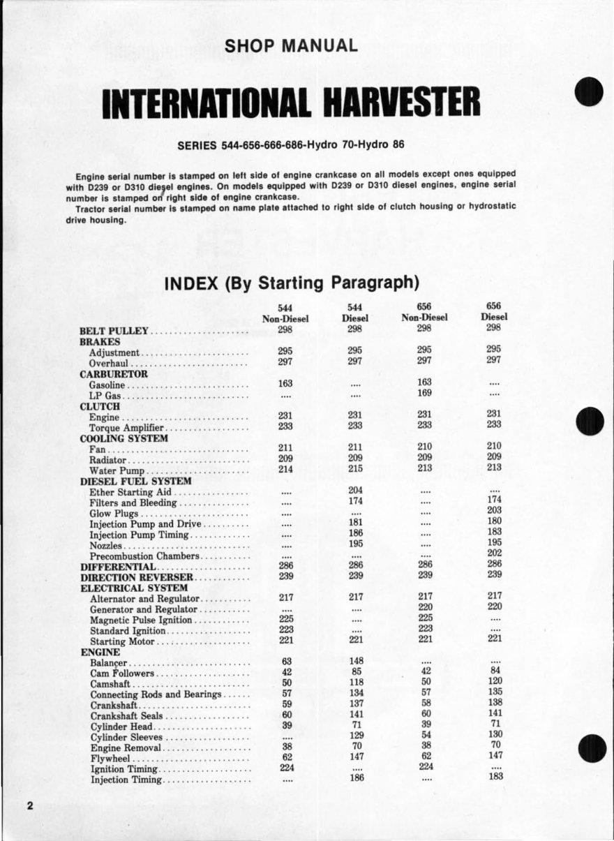
INDEX CONT. Hydro 70. 666, Hydro 10, Early Late 686, 666,686 Early 686 Hydro 86 Hydro 86 Hydro 86 NOD·~eHI Diellf'1 NOD·Diesel 01 ... ' DIe ... GOVERNOR ( Non ·Diesel) . .......... 205 205 HYDRAULIC SYSTEM Auxiliary Valves ... '" ........... 818 818 818 818 818 Auxiliary System Pump . .......... 2S 2S 2S 2S 2S Cylinder and Valve Unit . ......... SOB SOB SOB SOB SOB Lift Unit Pump . ............. . ... 814 814 814 814 814 R&R Lift Unit .. ................. S07 807 807 S07 S07 Test and Adjust . ........... '" ... 002 002 002 002 002 Trouble Shooting . ................ SOl SOl SOl SOl SOl HYDROSTATIC DRI VE AdjustmenLs .. ............... • . .. 249 249 249 249 249 Lubrication and Filter . ........... 278 278 278 278 278 FTe5sure Checks .. .......... ' .... 256 256 256 256 256 R&R and Overhaul . .............. 262 262 262 262 262 Trouble Shooting . ................ 248 248 248 248 248 POWER STEERING SYSTEM Cylinder .. ....................... S4 S4 S4 S4 S4 F10w Divider . ............... . ... SS SS SS SS SS Hand Pump ...................... 27 27 27 27 27 Lubrication and Bleeding . ......... 12 12 12 12 12 Oil Cooler . ...... . .. , .. . ....... .. 87 S7 S7 87 S7 Operational Testa . .. . ............ 15 15 15 15 15 • Pump . . . ...................... ,. 2S 2S 2S 2S 2S Steering Valves .. ... . ....... , .. ,. SO SO SO SO SO PrO Pressure. Check and Adjustment . . 299 299 299 299 299 R&R and Overhaul . ...... , ....... SOO SOO SOO SOO SOO TORQUE AMPLIFIER Linkage AdjWltment ., .. ....... . .. 2SS 2SS 2SS Overhaul T.A. Cluteh . ... , . . ...... 2S7 2S7 2S7 R&R and Overh aul T.A . ....... ... 2S8 2S8 2S8 TRANSMISSION, RANGE (Hydrostatie Drive) . .. ... ... . .. . .. 279 279 279 279 279 TRANS MISSI ON (Standard 5-Speed) .. ............. 240 240 240 CONDENSED SERVICE DATA ... ... 656 656 NOIl·DieMI 01 .... GENERAL NO D·DieMI Diesel Engine Model . .............. .. C200 D2S9 C26S D282 Number of Cylinder'S . ................ 4 4 6 6 Bore-Inebes . ....................... 3.812 8.875 8.56S 8.687 Stroke-Inehes ... .. . ................ 4.890 5.062 4.890 4.890 Displacement-Cubic Inches . ......... 200 2S9 263 282 Pistons Removed From .............. Top Top Top Top Main Bearinga. Number or . .......... . 8 5 4 4 Main and Rod Bearinga. Adjustable? .. No No No No Cylinder Sleeves . ................... W.t 0", lliy 5
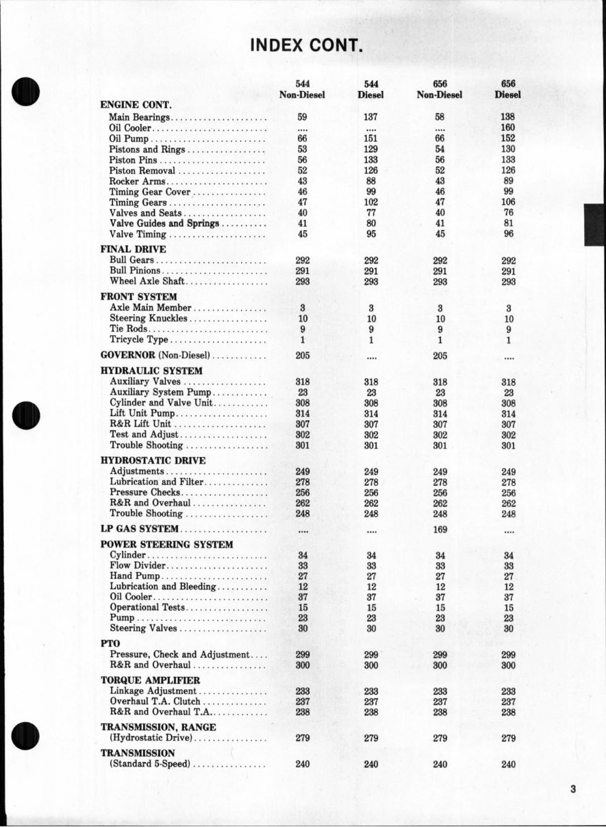
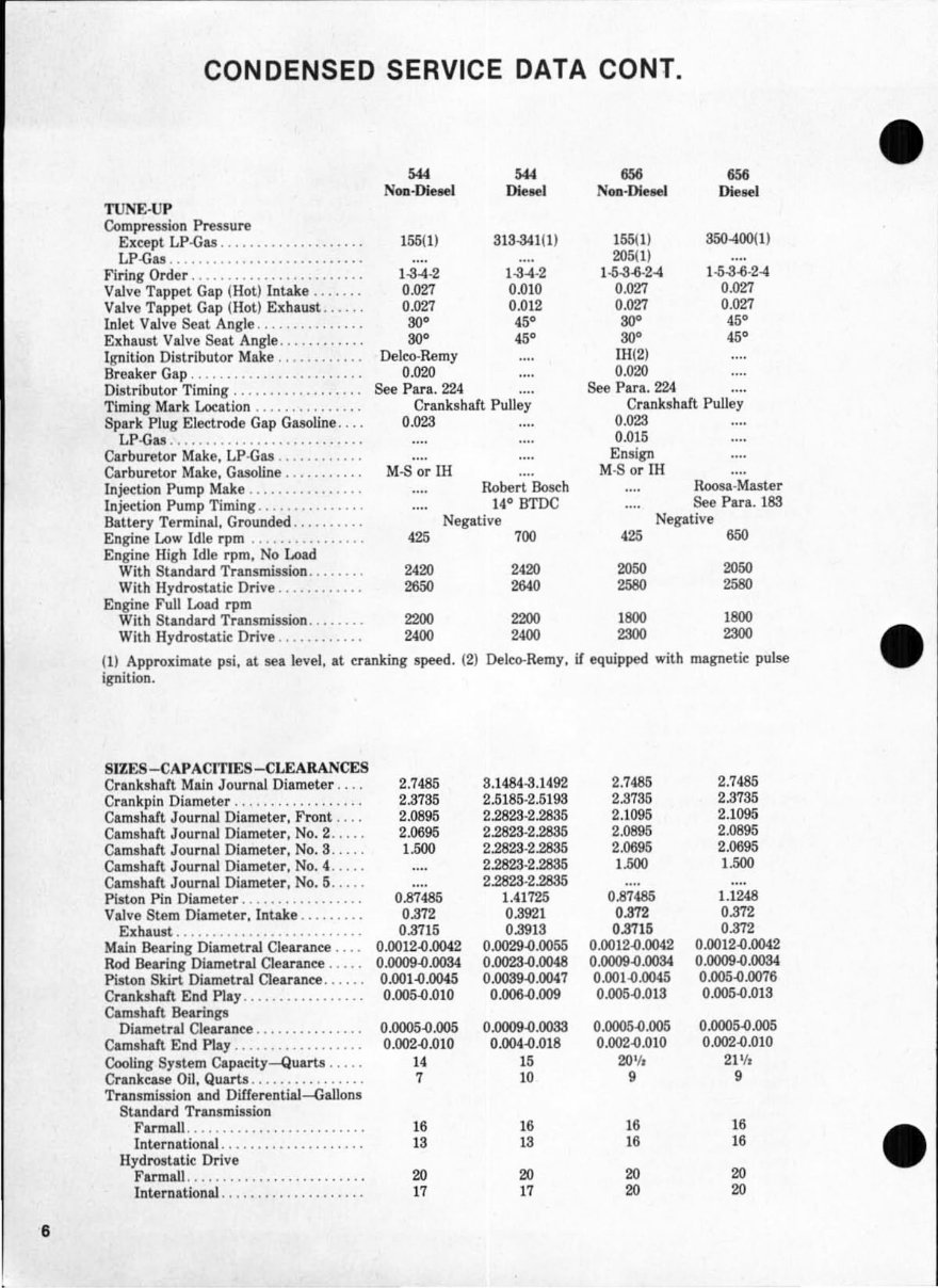
6 CONDENSED SERVICE DATA CONT. TUNE·Up Compression Pressure Except LP-Gas ................... . LP-Gas .......................... . Firing Order ....................... . Valve Tappet Gap (Hot) Intake ...... . Valve Tappet. Gap (Hot) Exhaust ..... . Inlet Valve Seat Angle .............. . Ex haust Valve Seat Angle ........... . Ignition Distributor Make ........... . Breaker Gap ....................... . Distributor Timi ng ................. . Timing Mark Location ............ •.. Spark Plug Electrode Gap Gasoline ... . LP-Gu .......................... . Carburetor Make. LP·Gas ........... . Carburetor Make. Gasoline .......... . lnjeetion Pump Make ............... . Injeetion Pump Timing .............. . Batte ry Terminal, Grounded ......... . Engine Low Idle rpm ............... . Engine High Idle rpm. No Load With Standard Transmission ....... . With Hydrostatic:. Drive ........... . Engine Full Load rpm With Standard Transmission ....... . With Hydrostatic:. Drive ........... . M4 Non-Dietel M4 Dieeel 155(1) SIS-341(1) 1-8.4·2 0.027 0.027 SO' SO' Delco-Remy 0.020 1-84·2 0.010 0.012 '5' '5' See Para. 224 Crankshaft Pulley 0.023 M-S or ill Robert Bosch 14° BTDC Negative 425 700 2420 2420 2650 2640 2200 2200 2400 2400 155(1) 205(1) 1-5-8-6·2.4 0.027 0.027 SO" SO" lH(2) 0.020 See Para. 224 650 Dieeel 350-400(1) 1-5-8-6·24 0.027 0.027 '5' '5' Crankshaft Pulley 0.023 0.015 Ensign M·S or rn Roosa- Master See Para. 183 Negative .25 650 2050 2050 2580 2580 1800 1800 2SOO 2SOO (1) Approximate psi. at sea level, at c:.ranking speed. (2) Delco-Remy, if equipped with magnetic:. pulse ignition. • SIZ ES-CAPACITIES-CLEARANCES Crankshaft Main Jour nal Diameter .. .. 2.7485 8 .1 484-8.1492 2.7486 2.7485 Crankpin Diameter . ........... . .... . 2.8785 2.5185·2.5193 2.8785 2.8785 Camsh aft Journ al Diameter, Front .... 2.0895 2.2825·2.2835 2.1095 2.1095 Camshaft J ournal Diameter, No.2 ..... 2.0695 2.2823·2.2885 2.0895 2.0895 Camshaft Journal Diameter , No. S . . ... 1 .500 2.2823-2.2886 2.0695 2.0695 Camsh aft J ournal Diameter, No.4 ..... 2.2828-2.2886 1.500 1.500 Camshaft Journal Diameter, No.5 ..... 2.2828-2.2885 Piston Pin Diameter ................. 0.87485 1.41725 0.87485 1.1248 Valve Stem Diameter. I ntake ......... 0.872 0.3921 0.872 0.872 Exhaust .......................... 0.3715 0.8918 037 15 0.872 Main Bearing Diametral Clearance .... 0.0012-0.0042 0.0029-0.0055 0.0012-0.0042 0.0012-0.0042 Rod Bearing Diametral Clearance ..... 0.0009-0.0034 0.0028-0.0048 0.0009-0.0034 0.0009-0.0084 Piston Skirt Diametral Clearance ...... 0.001-0.0045 0.0089-0.0047 0.001-0.0045 0.005-0.0075 Crankshaft End PI.y ................. 0.005-0.010 0.006-0.009 0.005-0.013 0.005-0.013 Camshaft Bearings Diametral Clearance ............... 0.0005-0.005 01lOO9-O.003S 0.0005-0.005 0.0005-0.005 Camshaft End Play .................. 0.002-0.010 0.004-0.018 0.002-0.010 0.002-0.010 Cooling System Capaeity-Quarts ..... 14 15 2(11/a 21 1 /, Crankcase Oil. Quarts ................ 7 10 9 9 Transmission and Differential-Gallons Standard Transmission Farmall ......................... IS IS IS IS Inter national ............... .. ... IS IS IS IS Hydrostat i c:. Drive Farm all ......... . ......... • ..... 20 20 20 20 I nte rnational .................... 17 17 20 20
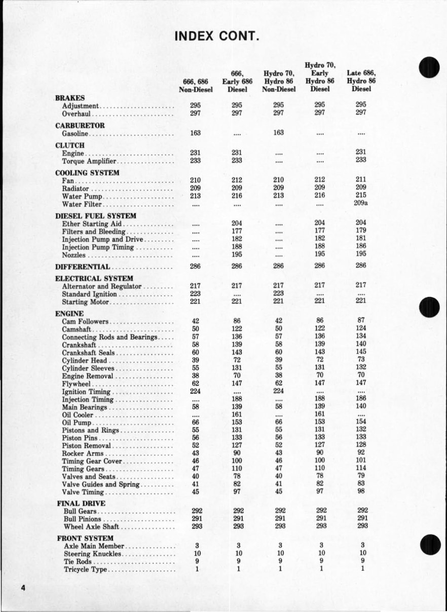
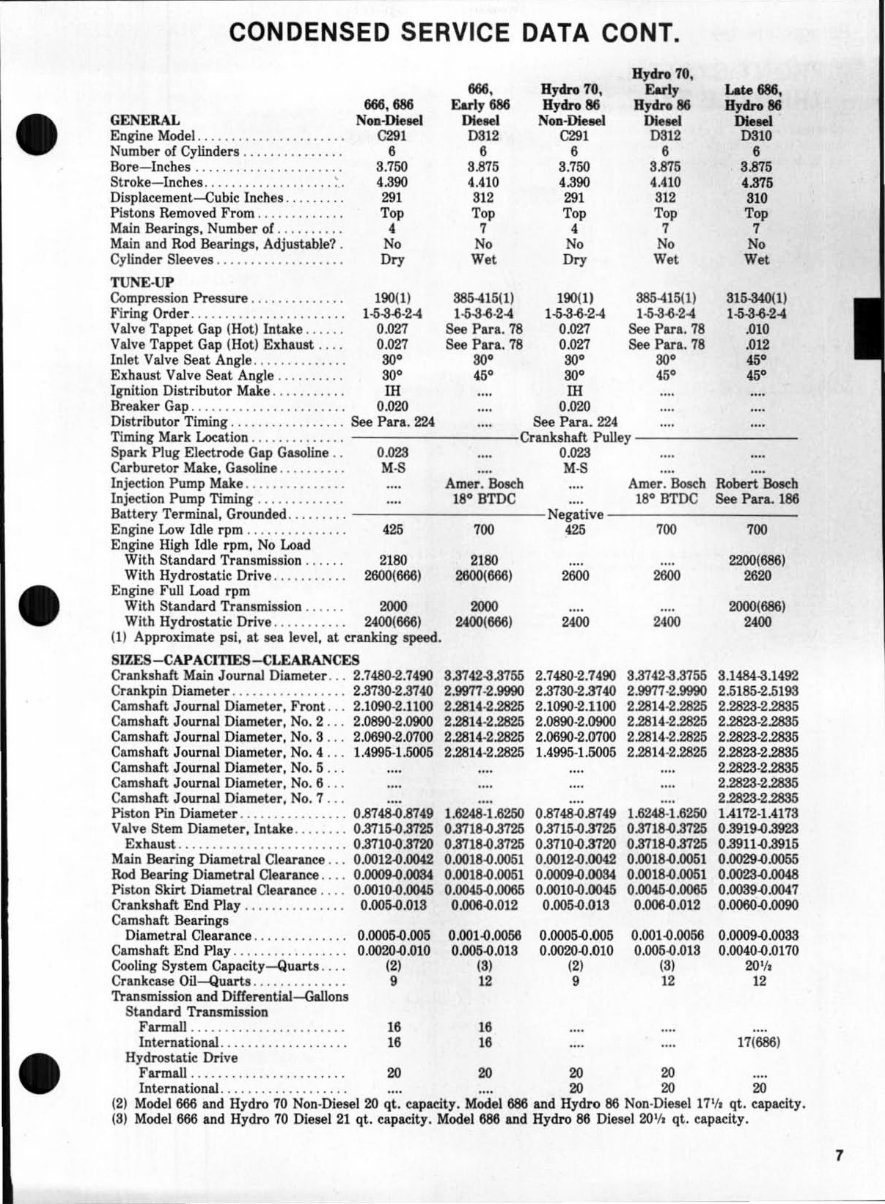
CONDENSED SERVICE DATA CONT. Hydro 70, 666. Bydro 10. Earl, Lote 686. 666.686 Earl,686 Hydro 86 Bydnt 86 Hydro 86 • GENERAL Non-Dietel DIeHl NOD-Die_ DIeHl DIeooI Engine Model. ......... , .. , .• ...... C291 0312 C291 D512 0310 Number of Cylinder-s ............... 6 6 6 6 6 &re-lnehes .. .................... 8.750 5~16 5.150 U16 5M6 Stroke-Inches . .............. .... _ .' '.390 4.410 • .390 4. 410 U16 Di!Jplacement~ubie Inches . .. . .. . .. 231 512 231 512 510 Pi!t.ons Removed From ............. Top Top Top Top Top Main Bearings, Number or .......... • 1 • 1 1 Main and Rod Bearings, Adjustable? . No No No No No Cylinder Sleeves ................... D", Wet 0.., Wet Wet TUNE-UP Compression Pressure .............. 1 90(1) S85-416(1) 190(1) S85-416(1) 516-340(1) Firing Order ...................... . 1-5-306·24 1-6-3-6· 2-4 1-5-3-6· 2-4 1-5-3-6· 2-4 1-5-3-6-2-4 Valve Tappet Gap (Hot) Intake ..... . 0. 021 See Para. 78 0.021 See Para. 78 .010 Valve Tappet Gap (Hot) Exhaust .... 0.021 See Para . 78 0. 021 See Para. 78 . 012 Inlet Valve Seat Angle .............. SO· SO" SO" SO" 45· Exhaust Valve Seat Angle .......... SO" '6· SO" 45· '5· Ignition Distributor Make ........... III III Breaker Gap ....................... 0.020 0.020 Distributor Timing ................. See Para . 224 See Para . 224 Timing Mark Location .............. Crankshaft Pulley Spark Plug Eledr'Ode Gap Gasoline .. 0. 023 0. 023 Carburetor Make. Gasoline .......... M-S M-S Injection Pump Make ............... Amer . Boeeh Amer. Bosc.h Robert Bosc.h Injection Pump Timing ............. 18° BTDC 18° BTDC See Para. 186 Battery TermiDai. Grounded ......... NegaUve Engine Low Idle rpm ............... 426 100 426 100 700 Engine High Idle rpm. No Load With Standard Tranamiaaion ...... 21SO 21SO 2200(686) With Hydrostatic Drive ........... 2600{666) 2600{666) 2600 2600 2620 Engine Full Load rpm With Standard Tranlmis!ion ...... 2000 2000 2000{686) With Hydrostatic Drive ........... 2400(666) 2400(666) 2400 2400 2400 (1) Approximate psi. at sea level. at cran1dng speed. SIZES-CAPACITIES -CL£ARANCES Crankshaft Main Journal Diameter ... 2.7480·2.7490 5.3142-3.3165 2.7480·2.1490 3.8742-3.8755 3.1484-8.1492 Crankpin Diameter ................. 2.3730·2.3140 2.9977·2.9990 2 nso- 2.3140 2.9971-2.9990 2.5185-2.5193 Camshaft Journal Diameter. Front . .. 2.1090-2.1100 2.2814-2.2825 2.1090-2.1100 2.2814-2.2825 2.2823-2.2885 Camshaft Journal Diameter. No.2 ... 2_0890- 2_0900 2.2814-2.2825 2.0890-2.0900 2.2814-2.2825 2.2828-2.2885 Camshaft Journal Diameter. No.3 ... 2.0690-2.0700 2.2814 ·2.2825 2.0690-2.()7oo 2.2814·2.2825 2.2823· 2.2835 Camshaft Journal Diameter. No.4 ... 1.4995-1.5005 2.2814-2.2825 1.4995-1.6005 2.2814·2.2825 2.2823- 2.2835 Camshaft Journal Diameter . No. 5 ... 2.2823· 2.2835 Camshaft Journal Diameter. No.6 ... 2.2828-2.2885 Camshaft Journal Diameter. No. 7 ... 2.2823· 2.2835 Piston Pin Diameter ........ '" ..... 0.8748-0.8749 1.6248-1.6250 0.8748-0.8749 1.6248-1.6250 1.4172·1A173 Valve Stem Diameter, Intake ........ 0.3715-0.3725 0.3718-0.8725 0.3715-0.3725 0.3718-0.3725 0.3919-0.8923 Exhaust ......................... 0.3710-0.8720 0.3718-0.3725 0.3710-0.3720 0.8718-0.8725 0.3911-0.3915 Main Bearing Diametral Clearance ... 0.0012-O.D042 O.oo18.{).1)(}51 0. 0012-O.0G42 0.0018-0.0051 O.OO29.o.Q055 Rod Bearing Diametral Clearance. . .. 0 .0009'{).0084 O.oo 18.{).Q051 0. 0009.0. 00S4 0.0018-0.0051 O.llO23-O.O0.8 Pi lton Skirt Diametral Clearance .... 0.0010'{).0045 0.0045.Q.OO66 0.0010-0.0045 O.Q046.o.0065 0.OO39.o.Q041 Crankshaft End Play ............ . .. 0.005-0.013 0.006-0.012 O.ClO5-O.otS 0.006.{).D12 0.0060-0.0090 Camlhaft Bearings Dlametral Clearance .............. 0.0005-0.005 0. 001.{) .0056 0.OOO5.{).IXl5 0. 001.{).0056 O .OOO9.o .OOSS Camshaft End Play .. ........ . ...... 0.0020 -0 .010 0.005-0.013 O.lXl20-O.010 0.005-0.013 0.0040.{) .0170 Cooling System Capacity-Quarta .... (2) (5) (2) (5) 20 1 /_ Crankcase Oil-Quarts .............. 9 12 9 12 12 Transmission and DiHerentiaJ-Gallons Standard Transmission Farmall ................. . ..... 16 16 International ................... 16 16 17(686) • Hydrostatic Drive Farmall ................... . ... 20 20 20 20 International ................... 20 20 20 (2) Model 666 and Hydro 70 Non-Diesel 20 qt . eapacity. Model 686 and Hydro 86 Non-Diesel 171 11 qt. eapacit;y. (3) Model 666 and Hydro 70 Diesel 21 qt. capacity . Model 686 aDd Hydro 86 Diesel 20 1 /1 qt . capacity. 7
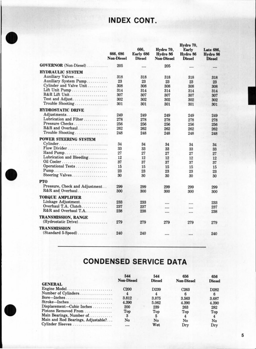
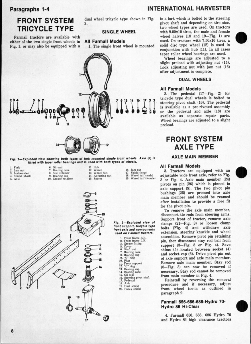
Paragraphs 1-4 FRONT SYSTEM TRICYCLE TYPE Farmall tractors are available with either of the two single front wheels in Fig. I, or may also be equipped with a INTERNATIONAL HARVESTER dual wheel tricycle type shown in Fig. 2. SINGLE WHEEL in a fork which is bolted to the steering pivot shaft and depending on tire size, two wheel types are used. On tractors with 9.00xl0 tires, the male and female wheel halves (18 and 19-Fig. 1) are All Farmall Models used. On tractors with 7.50x16 tires, a 1. The single front wheel is mounted solid disc type wheel (12) is used in , conjunction with hub (11) . In all cases taper roller wheel bearings are used. Wheel bearings ' are adjusted to a slight preload with adjusting nut (14). Lock adjusting nut with jam nut (16) after adjustment is complete. DUAL WHEELS All Farmall Models Ill~lIYn~ 1 ~, 2. The pedestal (17-Fig. 2) for tricycle type dual wheels is bolted to steering pivot shaft (16). The pedestal is available as a pre-riveted assembly or the pedestal and axle (18) are available as separate repair parts. Wheel bearings are adjusted to a slight preload. . 13 11 "-o~" Fig. 1-Exploded r/ew showing both types of fork mounted single front wheels. Axle (5) Is fitted with taper roller bearings and Is used with both types of wheels. 1. Fork 6. Oil seal 11 . Hu b 2. Jam nut 3. Lockwasher 7. Bearing cone 8. Seal retainer 12 . Wheel 13. Wheel bolt 4. Shield (s hort) 5. Axle 9. Bea ring cu p 10 . Grease retainer 1 4. Adjusting nut 15 . Spacer 8 16. Jam nut 17 . Shield (lo ng) 18. Wheel half (male) 19. Wheel half (fe male) Fig. 2-Exploded r/ew of front support, tricycle type front axle and components used on Farmall tractors. 1. Front frame R.H. 2. Front frame L.H. 3. Grease fitting 5. Cover 6. Shaft nut 7. Bear ing cone 8. Bearing cup 9. " 0" ring 10. Plug 11. Front support 12. "0" ring 13 . Bearing cup 14 . Bearing con e 15. Oil se al 16. Steering pivot shart 17 . Pede stal 18. Axle 19. Du st shield 20 . Pulley shield FRONT SYSTEM AXLE TYPE AXLE MAIN MEMBER All Farmall Models 3. Tractors are equipped with an adjustable wide front axle, refer to Fig. 3 or Fig. 4. Axle main member (24) pivots on pin ( 26) which is pinned in axle support (9). The two pivot pin bushings (25) are pressed into axle main member and should be reamed after installation to provide a free fit for the pivot pin. To remove the axle main member, disconnect tie rods from steering arms. Support front of tractor, remove axle clamps (21-Fig. 3) or loosen clamp bolts (Fig. 4) and withdraw axle extension, steering knuckle and wheel assemblies. Remove pivot pin retaining pin, then disconnect stay rod ball from support (3-Fig. 3 or Fig. 4). Save shims (5) located between socket (4) and socket cap (6). Drive pivot pin out of axle support and axle main member. Remove axle main member, Stay rod (S-Fig. 3) can now be removed if necessary. Stay rod cannot be removed from main member in Fig. 4. Reinstall by reversing the removal procedure and if necessary, adjust front wheel toe- in as outlined in paragraph 9. Farmall 656-666-686-Hydro 70- Hydro 86 HI-Clear 4. Farmall 656, 666, 686 Hydro 70 and Hydro 86 ,high clearance tractors
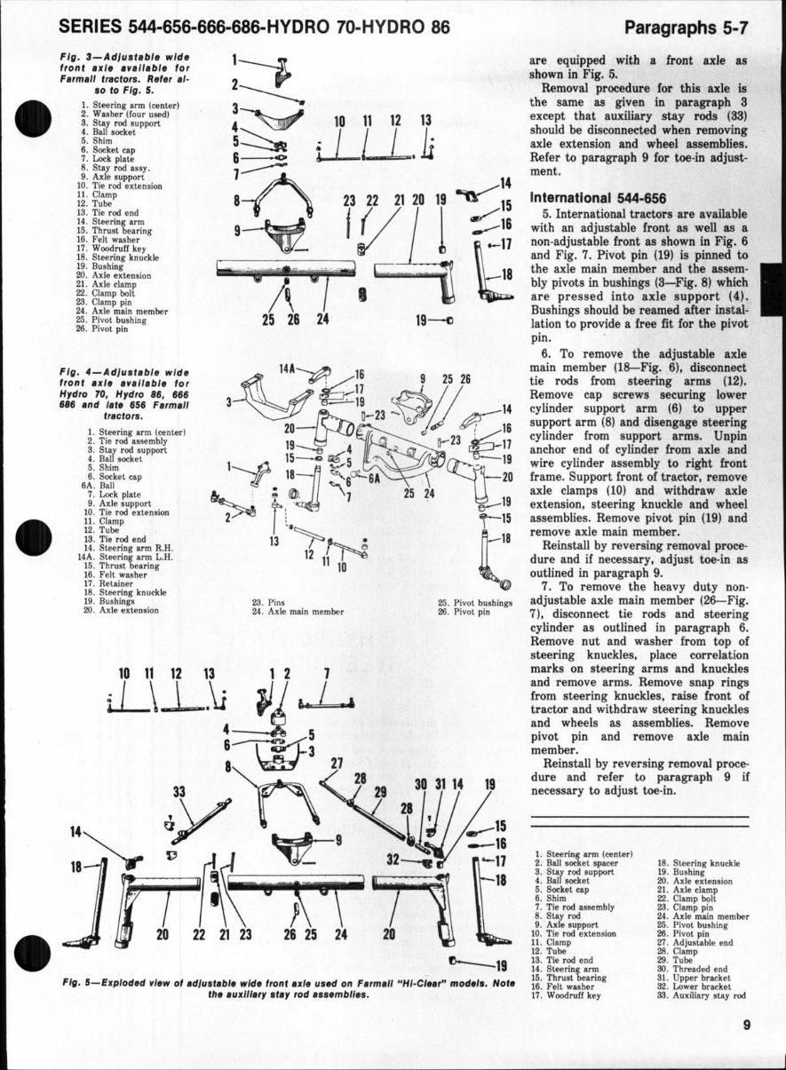
SE RIES 544-656-666-686-HYDRO 70-HYDRO 86 F' II . ' - Adl ll ." bl. wi d. f ron, 1111 , ."".0 1, lor ",,, ", 11 'flc lot •. II .,., .1· .0 10 Fig . 5. 1. S\.etn....r arm ('(Inter! 2. Wuller (four uwdJ S. SUI rod IUpport 4. Ball...ael 5. SlUra e. Satltel rap 7. Lock plate 8. Slay rod ... y. g, ,0\: 111 .. IUPport 10. TIe rod .nealion II. C1ll/11p 12. T\lbe IS. TIe rod end 14 . SIHriI!r U11I 15. Thl'lllt bearinl 16. rel l .lIher 11. Woodru fl' Iter 18. Steen,.. knu~klll 1&. Butllm, 20 ..... Ie IUI"nllion 21. A,1t claJllp 22. Clamp bolt 2.'1. Clamp pin 24. A_Ie maln member 25. Pivot bUlkwr 2111. Pivot p!n F ifl . 4- Ad /Ull b l. wid. fto nl ul, ".II., H, l or Hr dro 70. Hr dro , a, ,as ,It , ,.d III. ISf F.,m,1I '" Clor •. I. Steerillf.ll'tll (~nlerl 2. TIe rod _mbly 8. 51.&1 rod IUpport 4. Bal l llOdet S. Shim 6. Sorhl tap eA. Ball 7. Look pl ale 9. Ad .. IUpport 10. T;' rod ut"",1011 11 . ct.mp 12. Tube 13. TIe rod end 14 . 5leerill, arm R.H. 14" . &eerinr Inn l..H. 15. Thl'llst beaner II. Fell walIIer 1 1. Rttalnet" IS. SlHrin, knudtle 19. Bu.hln,. 00. Ade nUnlion 23 22 21 20 IV \;iii\;iii;;;;m' '''- ;iif ~o;;p' l~,,) I 25 26 24 19 --<> 1I1 ~~16 S 25 26 3 \ 19 "" ~ . 11 ~w, 20 "'Jh,. 0-23 - • q--:: 1S~~23 ~11 1 15- ~ 5 ' 19 ----f _ 11 ; ~6o:.: &1 ~20 "--- ' t ~ 1 25 24 \t-1S 13 ··~f--. 11 V'-l ! (5 12 11 l -.:e 10 23. Pi ... 1',6 . A~1e main member 25. Pivot buMin,. 211. Pivot. pin 10111213121 L\.L.~~~ - 3 6 W 5 a 21 33 n <J I ~ 21303114 II 14 aY '-- A ~tJJ __ 15 . , . ~8\ . m ~\·! k r 271 II 20 222123 J 25 24 20 ~11 Fig. 5-Eli plodH ,I." 0' .diu". bl. ,,'d. /ronl .~~ lI,ad on F., m.1I "HI·eIM'" mod.I,. Hoi . t il. ' Ul/I11", If ., lod .... mbll ••. Paragraphs 5-7 are equipped with a front axle as shown in Fi g. 5. Removal procedure for th is axle is the same as gi ven in paragraph 8 except that auxiliary stay rods (SS) should be disconnected when removing axle extension and wh eel assemblies. Refer to paragraph 9 for toe·in adjust- me nt . International 544--856 5. International tractors are available with an adjustable tront as well as a non -adjustable fro nt as shown in Fig. 6 and Fig. 7. Pivot pin (19) is pi nned to the axle main member and the assem- bly pivots in bus h ings. (S-Fig. 8) which are pres sed into axle suppo rt (4). Bus hings. should be reamed after inst al- lation to provide a free fi t for the pivot pin. 6. To remove the adjustable axle main member (l~Fig. 6), disconnect tie rod s from steering arms (12). Re move cap screws securing lower cylinder support arm (6) to upper support arm (8) and disengage steering cylind er from support arms. Unpin anchor e nd of cylinder from axle and wire cylinder asse mbly to right fro nt fram e. Support front of tractor, remove axle clamps ( 10) and withdraw axle exte nsion, steering knuckle and wheel assembli es. Remove pivot pi n ( 19) and remove axle mai n member. Reinstall by re versing removal proce- dure a nd if necessary. adjust toe-in as outlined in paragraph 9. 7. To remove the heavy duty non- adjustable axle main member (26--Fig. 7). disconnect tie rods and steering cylinder as outlined in paragraph 6. Remove nut and was her from top of steering knuckles, place correlation marks on steering arms and knuckles and remove arms. Remove snap rings. from steering knuckles. raise tront of tractor and withdraw steering knuckles and wheels as assemblies. Remove pivot pin a nd remove axle main member. Reinstall by reversing removal proce- dure and refer to paragraph 9 if necessary to adjust toe-in. \.5,""", arm !~nlV) 2. Ball .... t.t .pICe. a. Star rod .upport t. Bal .... t.t 5. Socket Clp S. Sblm 7. TIe rod .... mbly a. St&1" rod 8. A.re IUPport 1 0. Tie rod uun .... II . Clamp 11. Tu'" l a. TIe rod end It . SIHrinr ann 1 5. Th",rt beo.rin, 1 6. ".11 wulle. 17. Wood"," key 18. Sl.eerin, knuck. I'. BlIIohlDr 00. A ... nUnNon 21. A.1e damp 1!2 . Clamp boll 23. Clamp pili 2'. Axle maln member 26. Pivot builtin, 211. Pivot pin 11. Adjull.&bIe eI>d 28. a.mp 28. Tube 30 . Thl"Nded end 81. Upper brackel 32. Lcnrer b ... ket SiI. Au~m.1")' my rod 9
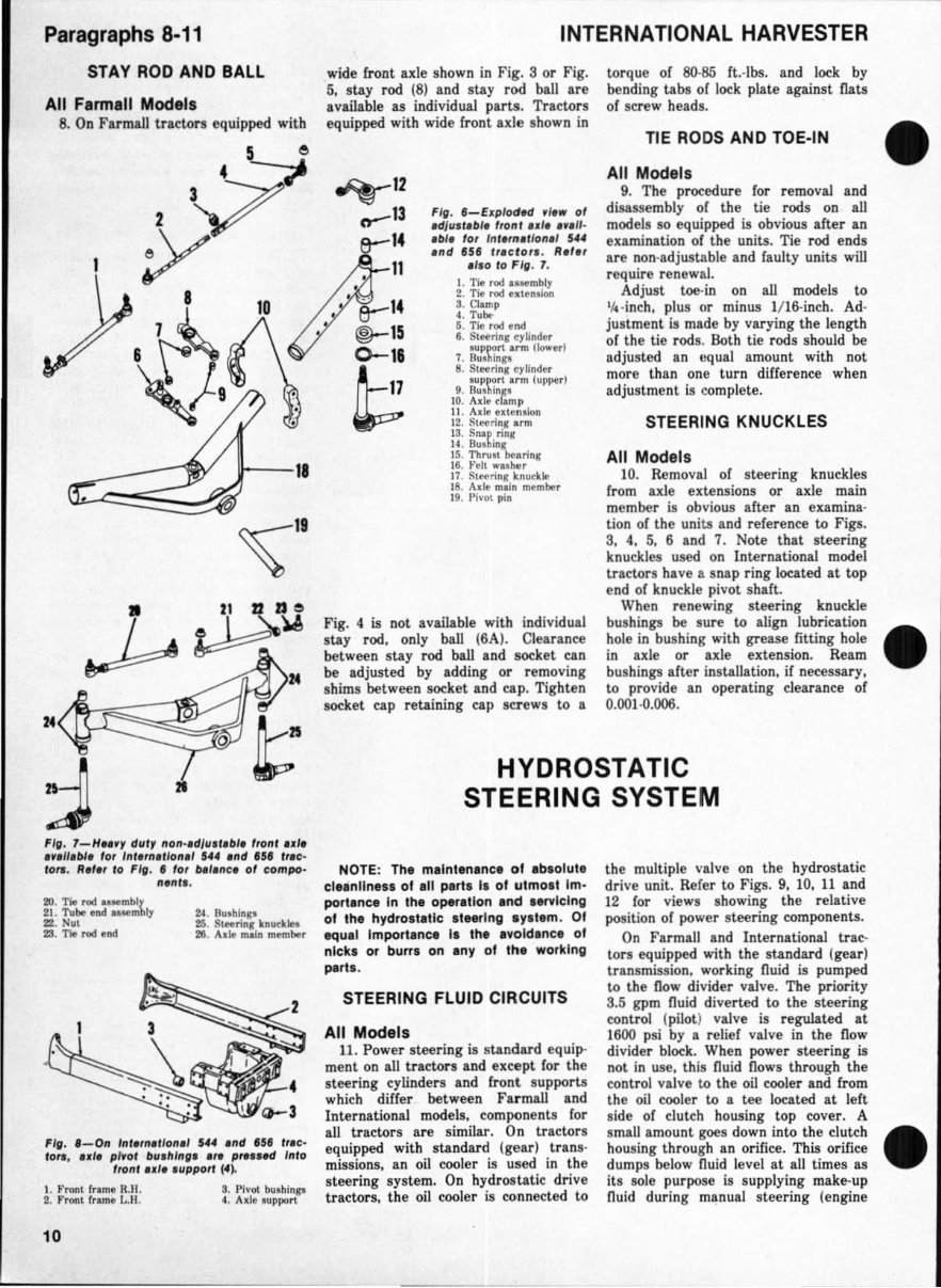
Paragraphs 8·11 STAY ROD AND BALL All Flrmlll Models 8. On FarmaU Lractors equipped witb 11--11 ~II 21 21 ZSe ~~ F/t . 1-HH', dill' IIon .. dl". ,.bl, "Ofl' 1.11. n.".IH. for I "It,n" k)n.' U4 ./ld U' '" C- 10,., R.,., 10 Fig . • lot ul,"c, 01 compo· II,nt, . • ~. BUlblII" 25. Slftrin, blltklN III. AI le "'""" _be. Fig. '-On '111.,,.,11011,1 $44 "11' '"~ '"c- to,., ul. ,,"01 Inl, II I,,", ." pre,," I nl o tronl .. I, ' lIppor' ff). I. .' , .. 11 f.ame R.H. 2. Fnlnl It.",.. 1..11 . 10 a. Pivot but.hlnp , . A.1e aupport INTERNATIONAL HARVESTER wide front axle shown in Fig. S or Fig. S, stay rod (8) and stay rod ball are available as individual parts. Tractors equipped with wide front axle ,hown in ~12 .,...-13 14 11 . - 14 e-- ®- 15 0-16 ~ FIg . '-EllplodH ,lew of .d/usl.b" Irof" 1.11. ",11· .bl. lOf Int.,tt,lIolt,' 5 •• '/ld U. '"clo". R.,., ,1'0 10FlfI. 1. I. TW roc! ..... mbly 2. Tie rod .. Ie ...... S. Clamp 4. Tub.. 5. Tie rod and I. S~rin. C)'~ ... ... p port a nn (lower' 7. 8~1h1n ... 8. 5Iee';n, eyUIl<Ier III PPOI"I .rm (upper ) 9. Buo~1nD 10. Ade crimp II. Ad ., ut .. nolon It. SI"rill,""" 1 3. Sill, rins 14 . Butlllllg 1$. ThruJl bot.ring Ie . relt .... hoo. \7 . S~rin, knudle 1 8. Ad .. maln melrl""'. I t. Pivot pia Fig. 4 is not available with individual stay rod, only ball (6A). Clearance between stay rod ball and socket can be adjusted by adding or removing shims between socket and cap. Tighten socltet cap retaining cap screws to a torque of 80-85 ft.·lbs. and lock by bending tabs of lock plate against Dats of screw heads. TIE RODS AND TOE·IN All Models 9. The procedure for removal and disassembly of the tie rods on all models so equipped is obvious after an examination of the units. Tie rod ends are non·adjustable Ind faulty units will require renew al. Adjust toe-in on all models to l A- inch, plus or minus IIl6-inch. Ad · justment is Il\Ade by varying the length of the tie rods. &th tie rods shou ld be adjusted an equal amount with not more than one turn difference when adjustment is complete. STEERING KNUCKLES All Models 10. Removal of steering knuckles from axle extensions or axle main member is ob vious after an examina· tion of the units and ref erence to Figs. S, 4, 5, 6 and 7. Note that steering knuckles used on International model tractors have a snap ring located at top end of knuck.1e pivot shaft. When renewing steering knuckle bushings be sure to align lubrication hol e in bushing with grease fitting hole in axle or axle extension. Ream bushings after installation. if necessary, to provide an operating clearance of O.O()1-O.006. HYDROSTATIC STEERING SYSTEM NOTE : The maintenance of ab.ol ute elel nllne •• 01 all part s Is 01 utmost Im - portance In the operation and .. rvlelng 01 the hydrostlUe .t .... lng .y.t.m. 01 aqual Importlnee II the avoidance 01 nicks or burrs on any of the working pa rt •. STEERING FLUID CIRCUITS All Models 11 . Power steering is standard equip- ment on all tractors Ind except for the steering cylinders I nd Cront lupport.s which differ between Farmall and International models. component.s for all tractors Ire similar. On trlctors equipped with standard (gear) trans· minions, an oil cooler is used in the steering system. On hydrostatic drive tractors, the oil coole r is co nn ected to the mUltiple valve on the hydrostatic drive unit. Refe r to Figs. 9, 10, 11 and 12 for views showing the relative position of power steeri ng components. On Farmall and International trac- tors equipped with the standard (gear) transmwion, working fluid is pumped to the now divider valve. The priority S.S gpm fluid di verted to the steering control (pilot) valve is regulated at 1600 psi by a relief valve in the now divider block. When power steering is not in use, this fluid flow. through the control valve to the oil cooler and £rom the oil cooler to a tee located at left side of clutch housing top cover. A small amount goes down into the clutch housing through an orifice. This orifice dum p! below fluid level at all times as its sole purpose is supplying make-up Ould during manual steering (engine
This manual is an essential resource for both professional mechanics and DIY enthusiasts working with IH International Hydro 70 and Hydro 86 tractors. It provides comprehensive instructions and step-by-step procedures for disassembling, repairing, and reassembling various components of the tractors, including the engine, electrical system, and worn-out parts.
The manual features detailed diagrams, illustrations, and specifications, offering valuable assistance in optimizing the performance and longevity of the equipment. It is a valuable investment for individuals seeking to confidently tackle any repair or maintenance task on their IH International Hydro 70 or Hydro 86 tractor.
Models covered in this manual:
IH International Hydro 70
IH International Hydro 86
Acquire this manual to gain the knowledge and expertise required to ensure the smooth operation of your tractor for years to come.
Recently Viewed
5,521,897Happy Clients
2,594,462eManuals
1,120,453Trusted Sellers
15Years in Business
Price:
Actual Price:
IH International Hydro 70 & 86 Tractor Shop Workshop Service Repair Manual - IMPROVED -