

' TOTHEOWNER
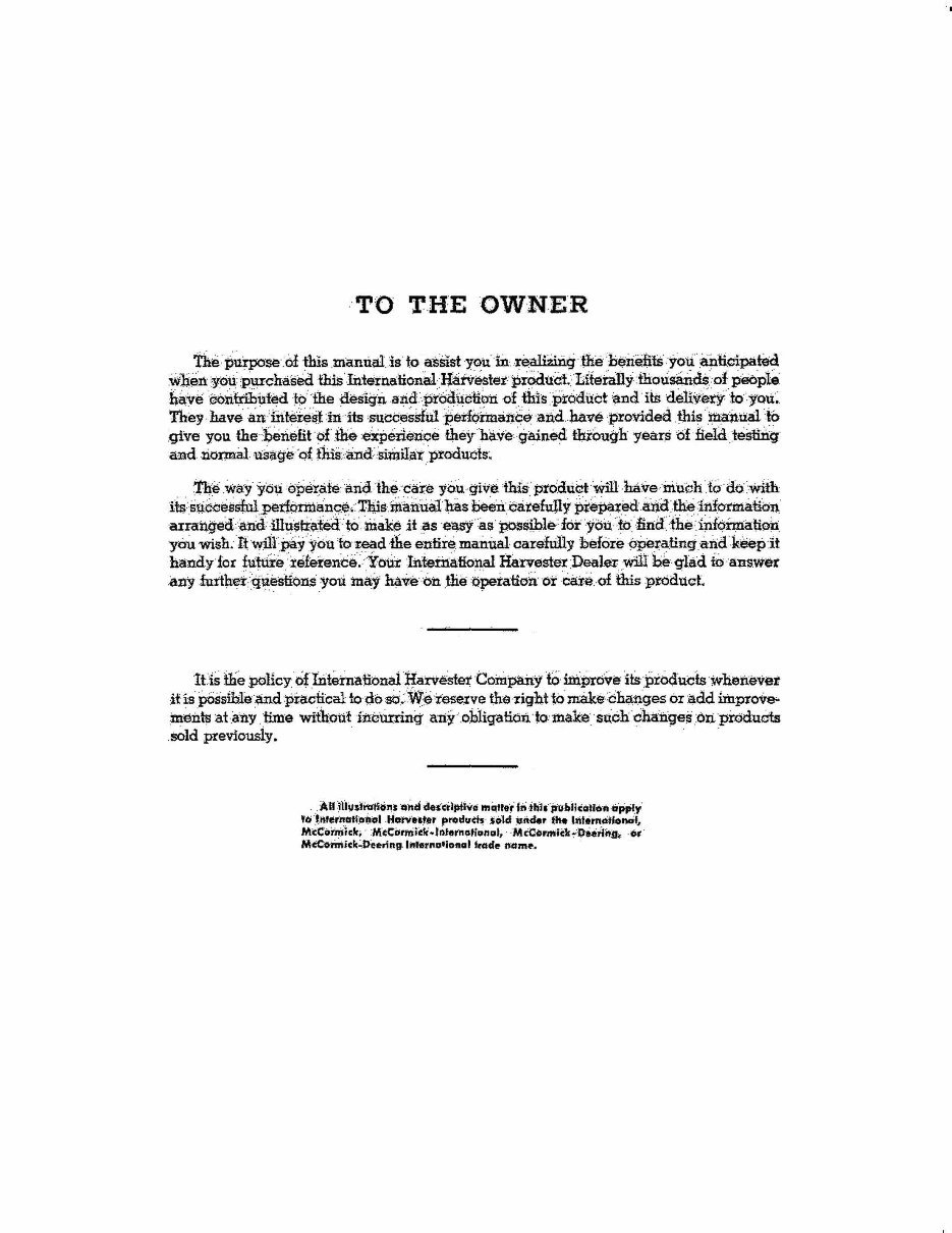
The purpose ol this mantial is to aSSlst you in .. ~ ·thehenelitSyoti. anticipated
h::::::Jb~~::s:::~~::n::~n~~t~:~:r~u:!~:::a::d~~U:U:~ '::;~~
They . have anmtEri:esl.inits ' successfulpenorlnanbeandh;aveprovidedthismanualio
give youtheJ;)enefitofthe-eXperienoeth.eybavegainedtbiough years of field testfug
andlionnallliia:~eof fh.isandsiri1ila:tproduds~
1h~way yotidperatearidth~carEi you give this prodtictWill have much fo do ·with
'~~r:~~:~:~~~f~ce~~::~~::!:~:::~~~::;~fi:~dt~:~~:r::=
you wish. It will pay you to read the entire manual carefully beforeoperatingaildkeep it
handy-for f\ittttexefeten6e~· YoUt Intefuational HarvesterDeal~ will be glad foanswer
any furtl;tetqueslions yoti may have bn the bpetatiollot ca:teof this product.
lfis the paHcyoflnteinatiOnalliarve'stetCOn1panyta mtprove ils ploouds whenever
it is pOssihle and practical to <10 st,;MtEitese,rve the right to make6hclnges or add improVe-.
msnts at any time without incumnq. anyohliqauo:ri to make sncilic:hangesonpi'Oducls
sold previousiy. · . . .
. . ' All ill\lsli'dtionltfnd d8Serljitive mal,., irithlljt(ibiicillll .. niiPPli
,o .lnte,naflIJilol .Hohl.'~r prodlfds· told ~ftder "'- hillimlrllonal.
McCormick. . N\(CiJ;.tnidc'. I Dh!1'II "ti .. n 01, . MCCormick ~DUrl"!hOl
MCCormick~O·e,,';ng. lnhll"D'ional "ade Inlmf'. .
"
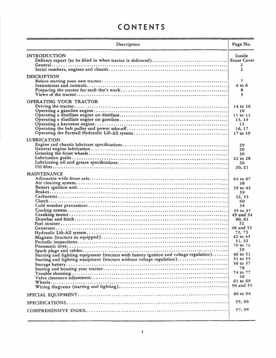
CONTENTS
I
Description i Page No.
-----------------------------------------------------------------------------1---------
INTRODUCTION ! Inside
Delivery report (to be iilied ill when tractor is delivered) ............. . .... , .... ' ............ 1 Front Cover
General .. " ................................................ . ............................. 1 2
DES~;~~;luc7~ers., engines and chassis ..... • .... ....................................... , . •... '1 2
Before starting your new tractor 0 •••••••••••••••••••••••••• • ••••••••••• - •• • •••••••••••••••• t 7
Instruments and controls 0 • • • • • • • • • • • • • • • • • • • • • • • • • • • • • • • • • • • • • • • • • • • • • • • • • • • • • • • • • • • • • • • • • 4 to 6
Preparing the tractor for each day's work ..... •...• ..•. .. , • ..... ....... ............... •.. ,. 8
Views of the tractor ........ '" ...... . ................................... ·.0' • • 0 •••••• •• ,. • 3
OPERATING YOUR TRACTOR
Drivin~ the tracto~ ...... : .. , ........... .. ........ , .................. , .................... .
OperatIng a gasoltoe engIne ........ .... .. _ ............................................... .
Operating a distillate engine on distillate .......................... _ ......... ....... .. ... .. .
Operating a distillate engine on gasoline . ................ •. , . ........ , ................. '" .
Operating a kerosene engine ....... , ... , ........... , . " .•.•... . .... ........... .. ............
Operating the belt pulley and power take-off ......................................... • .....
Operating the Farmall Hydraulic Lift·All system . ............. . ........... , ................ .
LUBRICATION
Engine and chassis lubricant specifications ....... ..... ....... •••• ........... • .... , ... .. ...•
General engine lubrication ...... . • .... .. ............ . ....................... . ..............
Greasing the front wheels, ....... • ..... .. .................................................
Lubrication guide ..••••..•...••.. , •.•..• .................. ••..•.•.••..•.•..•• ..........
Lubricating oil and grea~e specifications ..• ............ . ....................... . ............
Oil filter ....................................................... • ...................... ' ...
MAINTENANCE
AdjllStable "Wide front axle ... _ ...... • ........ •. .. .............. •...••••••. _ .. •..•...• , •.•••
Air clea.nin~. syste~ ......... . .......... . ............................ • .....................
Battery 19 n1tl0n unIt ................... . ..... • ....... •• ......... • ....... . .............. .. .
Brakes ........ . .. .. ... . .. _ ....... " ....... . ..................................... . ......... .
Carburetor .... . ...•... . .......................... . ........ . ........... .... ...... ... ......
Clutch ................................. .. ........................ ' . , .......... • .... .. . .. ,.
Cold weather precautions ... ' . .. ...• .......... 0 •• •• •• •• , ••••••••••••••••••••••••••••••• , •••
Cooling system .•.• ............... • ..... • ..... '. ' ........ ...•..•• .... • .... 0 ••••••••••••••• •
Cranking motor . •• .. • ..... .... ...•.• ....... , ............................................ .
Drawbar and hitch ....... •• •. .................................................. • ........ , .
Fuel strainer .... . .. ..... ........ ... . .... . ... ............... " ...................... . .. .. . . .
Generator ..• ........ ..... ........ •• .... • ......................... ........... ...... · . . · . . .
Hydraulic Lift-All system ........ " , ..... , ................ , ... .. ................ . ... .. . ... .
Ma~ne:o .( tracto:s so equipped) ..• .......... .... .. .. . ...... • ............. •. ...............
PerIodIC .Inspectlons ............. . ........................................ 0·' •••••• • •••••.•
PneumatIC utes ... . .................. • .................................................. ..
Spark plugs and cables ................. . ............. • ....... , . .. ......... . ' .•. : .......... .
Starting and lighting equipment (tractors with battery ignition and voltage · regulatlon) .. . ... .
Starting and lighting equipment (tractors without voltage regulation) ....... •. - .......... ' .. .
Storage battery .......... . ... .... ... .. . .. .. ................ •... ..... ' . .......... • - ....... . .
Storing and housing your tractor ..• , . .. .................... " .................... , .. . .. ... .
Trouble shooting ............................... • ....... , ... ........................... - ..
Valve clearance adjustment .. ........... . .... . ............ ... .................. . ...• ........
Wheels ...... ........... , .• ............................. . ..• ........... . .. .. .. , ....... ••..
Wiring diagrams (starting and lighting) ............................. , ...... . ...... . . • , ... .
SPECIAL EQUIPMENT ............... .. ............ ..... .... ... ... .. • .......................
SPECIFICATIONS ............. . ......... . .... . ...... . ............................ .. ........ .
COMPREHENSIVE INDEX ...... ... .• _. .... .... .. .. ... ..... .. .. ' ......... . .... ' ... . ... . .... .
14 to 16
10
11 to 13
13, 14
13
16, 17
17 to 19
29
20
30
22 to 28
30
20.21
64 to 67
38
39 to 42
59
32, 33
60
34
35 to 37
49 and 54
60,61
32
48 and 52
72,73
42 to 45
31, 32
70 to 72
39
46 to 51
51 to 55
56 to 57
78
74 to 77
58
61 to 69
50 and 55
80 to 94
95,96
97,98
INTRODUCTION
Assembled in this book are operating and mainte-
nance instructions for the FarmaH Hand HV, This
material has been prepared in detail in the hope that
it will ptove helpful to you in providing a better
understanding of the correct care and efficient
operation of your tractor.
If you should need information not g iven in this
manual, or require the services of a trained me-
chanic, get in touch with the International Harvester
dealer in your locality. Dealers are kept informed
on the latest methods of sen'icing tractors. They
carry stocks of IH parts, and are backed in every case
by the full facilities of a nearby International Har-
vester District Office.
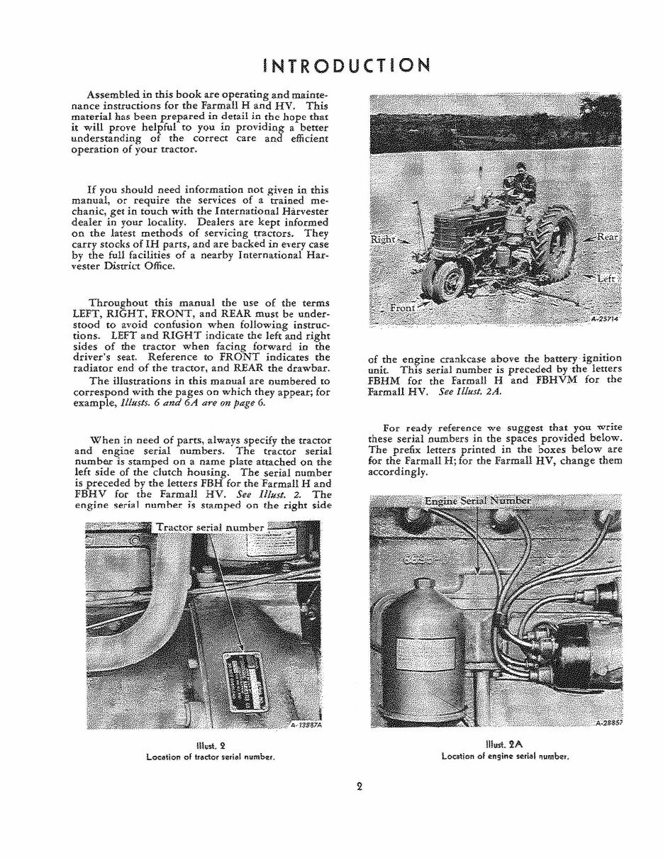
Throughout this manual the use of the terms
LEFT, RIGHT. FRONT, and REAR must be under-
stood to avoid confusion when following instruc-
tions. LEFT and RIGHT i ndicate the left and right
sides of the tractor when facing forward in the
driver's seat. Reference to FRONT indicates tbe
radiator end of the tractor, and REAR the drawbar.
The illustrations in this manual are numbered to
correspond with the pages on which they appear; for
example, Jllusts. 6 and 6A are on page 6.
When in need of parts, always specify the traCtor
and engine serial num b ers. The tractor serial
numbe.r is stamped on a name plate attached on the
left side of the dutch hou sing. The serial number
is preceded by the letters FBH for the Farmall Hand
FBH V for the Farmall HV. See Iilltst. 2. The
engine seria I nnm her. ,'s stamped on the right side
1II~5t. 2
Locat io!! of tr.,ctor $eri~1 nllmbet.
2
of the engine crankcase above the battery ' ignition
unit. This serial number is preceded by , the letters
FBHM for the Farmall Hand FBHVM for the
Farmall HV. See llittst. 2A.
For ready reference we suggest that you write
these serial numbers in the spaces provided below.
The prefix letters printed in the boxes below are
for the Farmall H; for the Farmall HV, change them
accordingJ y.
must. 2A
Location of en9in~ serial "umber.
DESCRIPTION
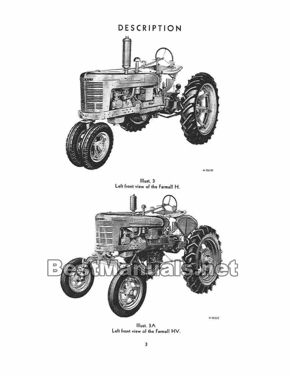
lIIust. 3
left front view of the F.s"m~1I H.
lIIust. 3A
left front view of the farm.1I HV.
3
DESCRIPTION
Instruments and Controls
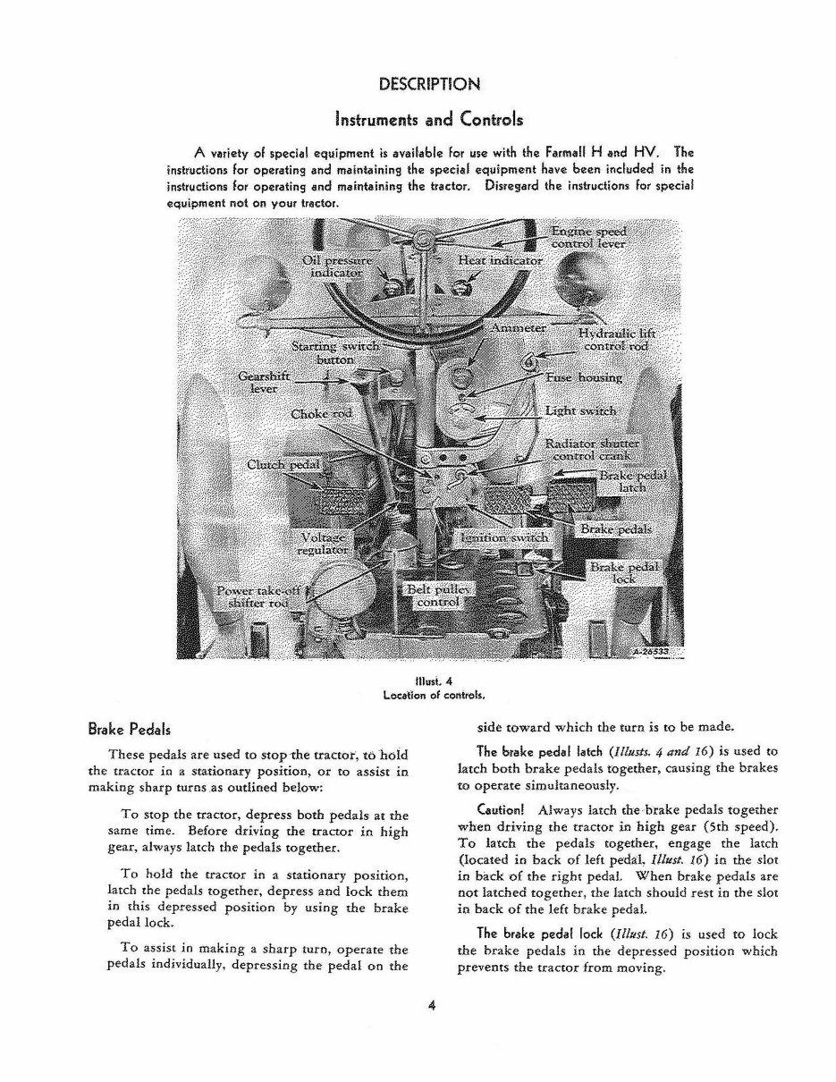
A variety of special equipment is available for use with the Farmall Hand HV. The
instructions for operating and maintaining the special equipment have been included in the
instructions Eor operating and maintaining the tractor. Disresard the instructions for special
equipment not on your tractor.
lIIust. 4
Local'ion of controls.
Brake Pedals
These pedals are used to stop - the tractor, to -hoid
the tractor in a stationary position, or to assist in
making sbarp turns _as outlined below:
To Stop the tractor, depress both pedals at the
same time. Before driving the tractor in high
gear, always latch the pedals together.
To hold the tractor in a stationary position,
latch the pedals together, depress and lock them
in this depressed position by using the brake
pedal lock.
To assist in making a sharp turo, operate the
pedals individually, depressing the pedal on t he
4
side toward which the turn is to be made.
The brake pedal lo1tch (lllllsts. 4 and 16) is used to
latch both brake pedals together, causing the brakes
to operate simultaneously.
Caution! Always latch the brake pedals toge.her
when driving the tractor in high gear (5th speed).
To latch the pedals together, engage the latch
(located in back of left pedal, IIlust. 16) in the slot
in back of the right pedal. When brake pedals are
not latched together , the latch should rest in the slot
in back of the left brake pedal.
The brake pedal lock (Illust. 16) is used to lock
the brake pedals in the depressed position which
prevents the tractor fr om moving.
DESCRIPTION
Clutch Pedal
This pedal, when depressed all the way, dis-
engages the engine from the transmission.
Choke Rod
The choke rod makes it possible to regulate the
carburetor choke from the driver's seat. Pulling
out on the choke rod doses the carburetor choke
for starting the engine; pushing it back in opens
the choke.
Carburetor Choke Lever
(Tractors without Cranking Motor)
The carburetor choke lever controls the air
supply to the carburetor. When the choke lever
is moved toward the rear (closed position), the air
supply is cut off, thereby enriching the fuel mixture
for starting the eogine. Move the carburetor choke
lever all the way to the rear before cranking the
eogine . Moving the choke lever forward opens the
choke for normal engine operation.
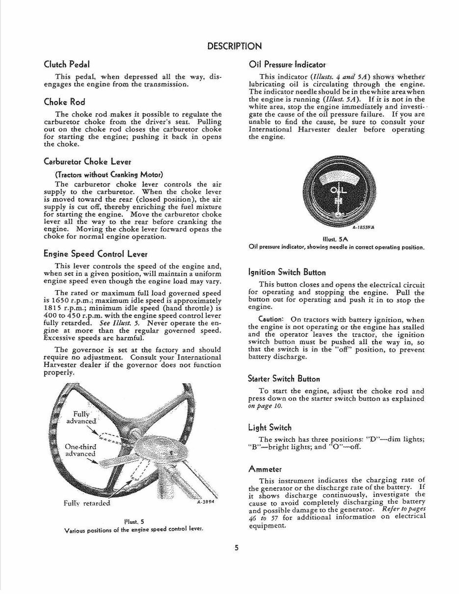
Engine Speed Control Lever
This lever controls the speed of the engine and,
when set in a given position, will maintain a uniform
engine speed even though the engine load may vary.
The rated or maximum full load governed speed
is 1650 r.p .m.; maximum idle speed is approximately
18 1 5 r. p.m.; minimum id Ie speed (hand throttle) is
400 to 450 r.p.m. with the engine speed control lever
fully retarded. See IIlust. 5. Never operate the eo-
gine at more than the regular governed speed.
Excessive speeds are harmful.
The governor is set at the factory and should
require no ad justm em. Consult your I mernational
Harvester dealer if the governor does not function
properly .
Funy retarded
I'lust. 5
Variou~ positions of the ensine speed control lever.
5
Ojl Pressure' Indicator ·
This indicator (lllJ4sts. 4 and 5A) showswhethet
lubricating oil is circulating through the engine.
The indicator needle should be in the white area when
the engine is running (fUust. 5A). If it is not in the
white area, Stop the engine immediately and investi- -
gate the cause of the oil pressure failure. If you are
unable to find the cause. be sure to consult vour
International Harvester - dealer before operating
the engine.
must. SA
Oil prelisure indicator, showins needle in correct operating position.
Ignition Switch Button
This button closes and opens the electrical drcuit
for operating and stopping the engine. Pull the
butt:.lD out for operating and push it in to stop the
engme.
Caution: On tractors with battery ignition, when
tbe engine is not operati ng or the engine has stalled
and the operator leaves the tractor, the ignition
switch button must be pushed all the way in, so
that the switch is in the "off" position, to prevent
battery discharge .
Starter Switch Button
To start the engine, adjust the choke rod and
press down on the starter switch button as explained
on page 10.
Light Switch
The switch has three positions: "D" -dim lights ;
"B"-brigbt lights; and " O"-off.
Ammeter
This instrument indicates the charging rate of
the generator or the disch~7ge t ate of ~he ba.ttery. If
it shows discharge cont1!luously, investigate the
cause to avoid completely discharging the battery
and possible damage to the generator . Refer to pa,ges
46 to 57 for additiona l information on electrIcal
equipment,
DESCRIPTION
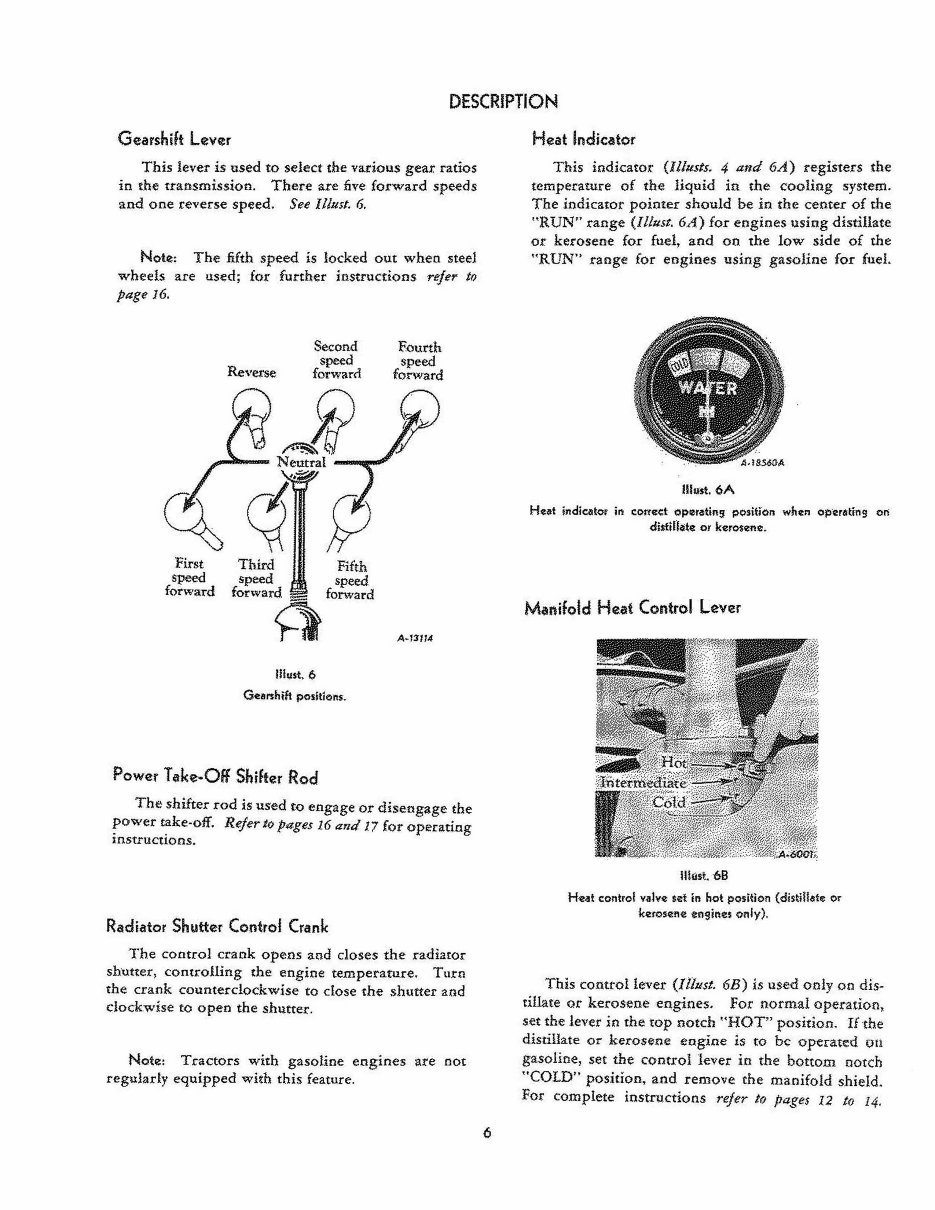
Gearshift Lever
This lever is used to select the various gear ratios
in the transmission. There are five forward speeds
and one reve rse speed. See I1/usl. 6.
Note: The fifth speed is locked out when steel
wheels are used; for further instructions refer to
page 16.
First
speed
forward
Reverse
Second
speed
forward
Third Fifth
speed speed
fo'W'~ fo"".-d
liIust. 6
Gearshift positIons.
Power Take-Off Shifter Rod
Fourth
speed
forward
A-13174
The shifter rod is used to engage or disengage the
power take-off. Refer to pages 16 and 17 for operating
instructions.
Radiator Shutter Control Crank
The control crank opens and closes the radiatOr
shutter, controlling [he engine temperature. Turn
the crank counterclockwise to dose the shutter and
dockwise to open the shutter.
Note: T.ractors with gasoline engines are not
regularly equipped with this feature.
6
Heat Indicator
This indicator (I1lusts. 4 and 6A) registers the
temperature of the liquid in the cooling system.
The indicator pointer should be in the center of the
"RUN" range (Illust. 6A) for engines using distillate
or kerosene for fuel, and on the low side of the
"RUN" range for engines using gasoline for fuel.
lIIust.6A
Heltt indicat-or in cortII'd operating position when op'crati ng on
distillate 01 kerOienl!:.
Manifold Heat Control Lever
\Hust. -68
Heat control ""Ive set in hot position (distillate or
kero$cn~ eogines only) .
This conttollever (Illust. 6B) is used only on dis-
tillate or kerosene engines. For normal operation,
set the lever in the top notch "HOT" position. If the
distillate or kerosene engine is to be operated on
gasoline, set the control lever in the bottom notch
"COLD" position, and remove the manifold shield.
For complete instructions refer If) pages 12 to 14.
DESCRIPTION
Before Starting Your New Trador
Lubrication
Lubricate the entire tractor, using the "Lubrica.
tion Guide" (page 22) as a guide.
Check the oil levels of the eogine crankcase, air
deaner, transmission, belt pulley housing, and all
gear cases to see that they are filled to the corre(.'t
levels with the proper grade of oil for the preva iling
temperature. Reje~' to the "Lubrication Guide" on
page 22, and to the specifications of lubricants on pages
29 and 30.
Tractors shipped to destinations in the: Unit~d S~at~$
of America Canada and Mexico are nUed WIth 011 In
all parts before leaving the factory. Engines are
filled with a light eng i ne oil. However, this is for
preservative purposes only and is not suitable for
regular service. The original oil should be drained
from the crankcase and air cleaner and replaced with
the required amount of fresh oil for the preyailing
temperature.
Tractors packed for export have all oil drained from
the engine crankcase, air cleaner and all gear cases .
Before starting the engine for the first time, remove the
spark plugs and put about ODe teaspoonful of crank-
case oil into each cylinder; replace the spark plugs
and crank the engine to distribute the oil over the
cylinder walls . This assures positive lubrication of
the cylinders and pistons immediately after starting
and eliminates the possibility of scoring.
Pneumatic Tires
Before moving the tractor, check the air pressure
in the pneumatic tires and inflate Or deflate the front
and rear tires to the correct operating pressures.
Refe1' to the chart on page 70.
SteeJ Wheels
If your tractor is equi pped with steel wheels, or
has new wheel and lug installations, it is advisable
to check and tighten the.·.rear wheel bolts at intervals
to be sure that the lugs seat properly.
Engine Cooling System
The cooling system capacity is approximately
16~ U. S. quarts .
Be sure the radiator drain and crankcase water
drain (II/list. 36) are dosed, tben fill the radiator to
a level approximately 2y,( ioches below the top of
7
the nIler neck. Filling the radiator to this level will
allow for expansion of the coolant under normal
operating conditions. Use dean water; soft or rain
water is recommended, as it does not contain alkali,
which forms scale and eventually clogs the passages .
When filling the rad i ator, remove the veot plug
in left side of thermostat housing (Ill list. 36) and
replace the plug when water appears .
Never start or operate the engine without water
or antifreeze inthe cooling system except as instructed
i1J "Cold Weather Precautiom" on page 34.
For further information see "Cooling System"
(page 35). If the tractor is to be operated in fre~zing
temperatures (+ 32 0 F. or lower) refer to Cold
Weather Precautions" on page 34.
Fuel System
Provision is made in the design of this tractor so
that it may be equipped wi th either a gasoline, dis-
tillate, or kerosene-burning engine. Before attempt-
ing to use a fuel for which your tractor is not
designed, see your International Harvester dea~er ~)J;
the nearest International Harvester Company DistrIct
Office for full details.
To obtain best results, use the fuel for which the
tractor .is designed, follow the operating instructions
given for that fuel and observe the following pre -
cautions:
1. Distillate fuels should conform to International
Harvester Company specifications (see your Inter-
national Harvester dealer).
2. Distillate or kerosene-burning tractors should
not have the shut-off valve under the auxiliary tank
and the one under the main fuel tank open or even
partially open at the same time, as this will permit
the distillate or kerosene to mix with the gasoline,
making the engine hard to start.
3. During the first 100 hours of operation , mix
one pint of light engine oil with every five U. S.
gallons of fuel.
Ign ition-Electrica I
Tractors shipped from . the factory with starting
and lighting equipment have the "battery to ground "
cable disconnected and taped. Therefore, before
attempting to start the engine. be sure the "battery
to ground" cable is connected to the ground.
Instruments and Controls
Thoroughly acquaint yourself with aU instruments
and controls as described on pages 4 to 6.
DESCRIPTION
N~ver refuel tractor while engine is running
or extremely hot.
Preparing Your T ratter
For Each Day·s Work
Fuc;:1 System
Fill the fuel tank (capacity 17 Y2 U. S. gals.) rrefer-
ably at the end of each day 's work. This wi! force
out any moisture-laden air and prevent condensation.
Tractors designed for distillate or kerosene
operation have an auxiliary tank (capacity Ji U. s.
gallon) for gasoline, w hich is used only for starting
and warming up the engine. If a distillate or kero-
sene engine is to be operated on gasoline only, use
the large fuel tank for gasoline and either shut off
the small tank or " use it as an auxiliary tank.
The filler caps on both fuel tanks have air vents.
These vents should be kept open at all times to
assure proper .flow of the " fuels. See IUust. SA.
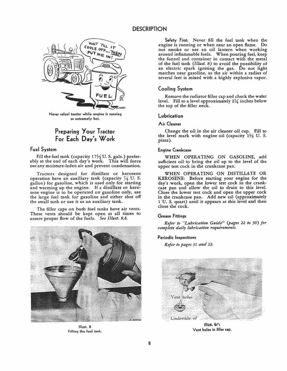
lIIust. 8
Filling the fuel tank.
8
Safety First: Never fill the fuel tank when the
engine is running or when n, ear an open flame. Do
not smoke or use an oil lantern when working
around inflammable fuels. When pouring fuel, keep
the funnel and container in contact with the metal
of the fuel tank (Illust. 8) to avoid the possibility of
an electric spark igniting the gas . Do not light
matches near gasoline , as the air within a radius of
several feet is mixed with a highly explosive vapor .
Cooling System
Remove the radiator fillet cap and check the water
level. Fill to a level approximately 2)i inches below
the top of the filler neck.
Lubrication
Air Cleaner
Change the oil in the air cleaner oil cup. Fill to
the level mark w ith engine oil (capacity 1% , U. S.
pi nts).
Engine Crankcase
WHEN OPERATING ON GASOLINE; , add
sufficient oil to bring the oil up to the level of the
upper test cock in the Cril.llkcase pao.
WHEN OPERATING ON DISTILLATE OR
KEROSENE: Before starting your engine for the
day's work, open the lower test cock in the crank.
case pan and allow the oil to drain to this level.
Close the lower test cock , and open the upper cock
in the crankcase pan. Add , new oil (approximately
I- U, S. quart) until it appears at this level and then
close the cock.
Grease Fittings
ReJer to "Lubrication Guide" (pages 22 to 30) Jor
complete daily lubrication ,·equirements.
Periodic Inspections
ReJer to pages 31 and 32.
IIhm, 'Q(,
Vent holll$ln filler cap.
You're Reading a Preview
What's Included?
 Lifetime Access
Fast Download Speeds
Online & Offline Access
Access PDF Contents & Bookmarks
Full Search Facility
Print one or all pages of your manual
$31.99
Farmall H, HV Operators Owners Manual IH Tractor International
Viewed 73 Times Today

What's Included?
Lifetime Access
Fast Download Speeds
Online & Offline Access
Access PDF Contents & Bookmarks
Full Search Facility
Print one or all pages of your manual
$31.99


Secure transaction
What's Included?
Lifetime Access
Fast Download Speeds
Online & Offline Access
Access PDF Contents & Bookmarks
Full Search Facility
Print one or all pages of your manual
Description
Get the comprehensive Owners/Operators Manual for the 1939-1953 Farmall H & HV Tractor. This manual, identical to the original, covers all essential aspects of your tractor, including maintenance procedures, lubrication, special attachments, specifications, and operating instructions.
- Instant access - no waiting
- Available in PDF format
Key specifications for the Farmall H Tractor:
- Model history: introduced in 1939 and discontinued in 1953
- Engine: International C-152, 4 cylinders, 152 ci displacement, 24 hp belt, 20 hp drawbar
- Transmission: sliding gear, 5 forward, 1 reverse, 2-WD
- Dimensions: 125" length, 76" width, 74" height, 3335 lb weight, 89" wheelbase
- Additional info: manufactured at Tractor Works, Chicago, Illinois; plow rating of 2-14"; Nebraska Tests No. 333; approximate cost new in 1941 was $962
Key specifications for the Farmall HV Tractor:
- Model history: introduced in 1942 and discontinued in 1953
- Engine: International C-152, 4 cylinders, 152 ci displacement, 24 hp belt, 20 hp drawbar
- Transmission: sliding gear, 5 forward, 1 reverse, 2-WD
- Dimensions: 147" length, 86" width, 87" height, 4430 lb weight, 92" wheelbase
- Additional info: manufactured at Tractor Works, Chicago, Illinois; plow rating of 2-14"; Nebraska Tests No. 333


