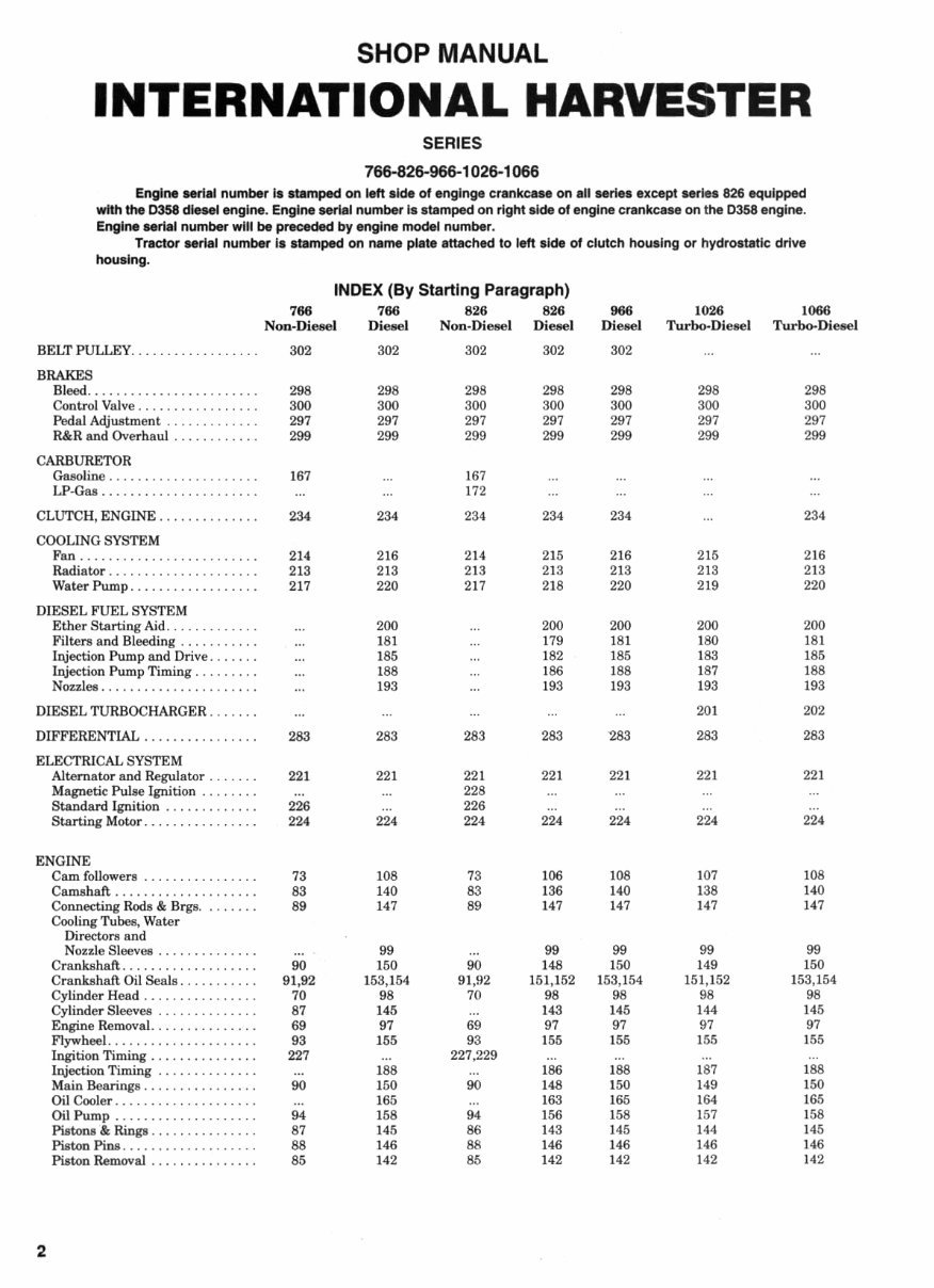
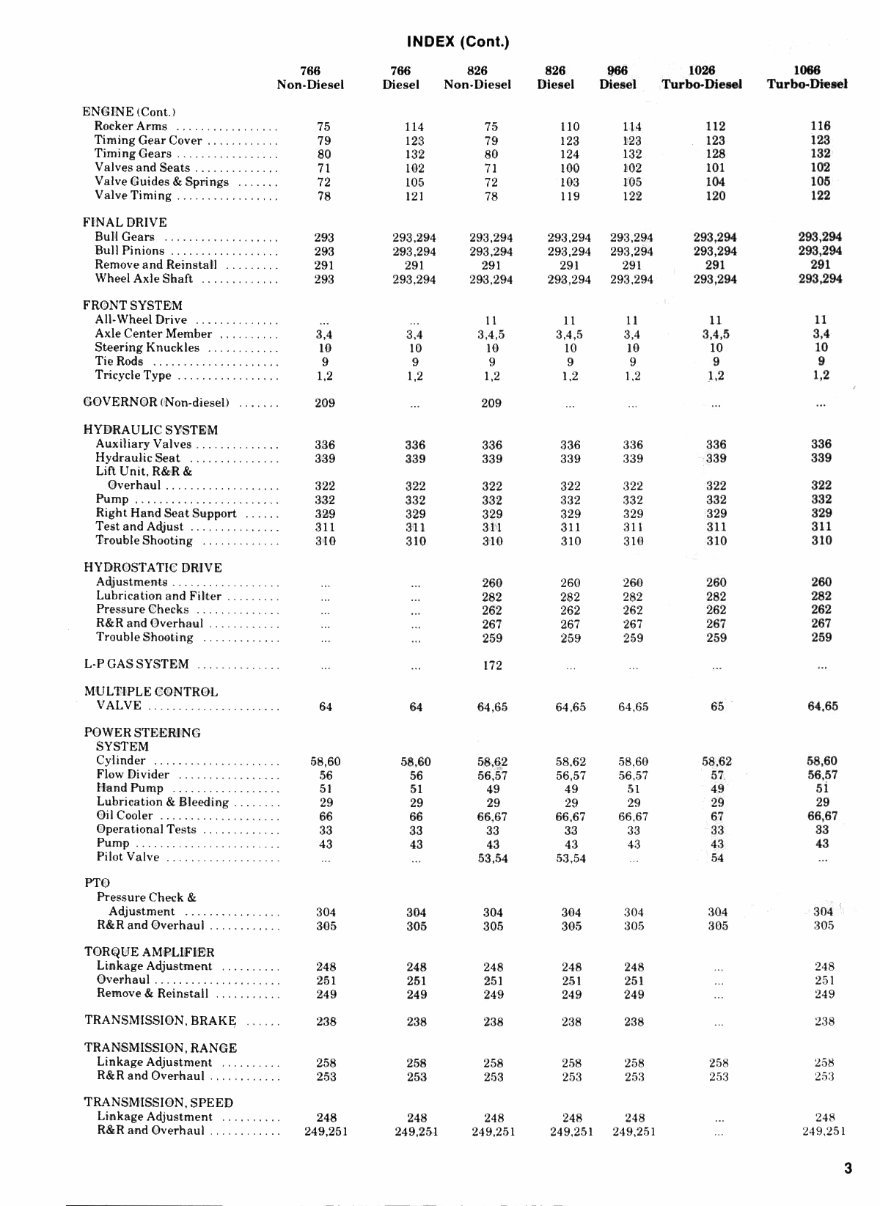
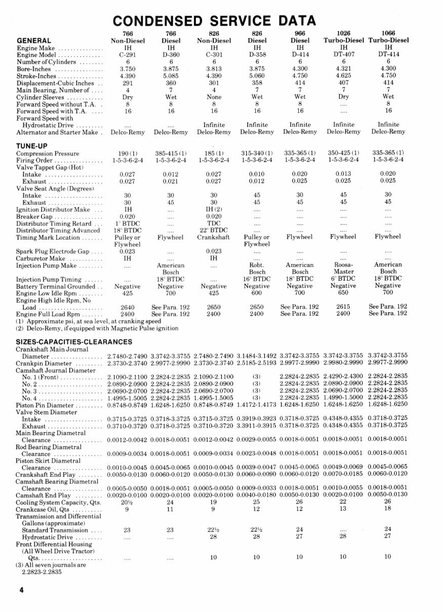
CONDENSED SERVICE DATA 766 766 826 826 966 1026 1066 GENERAL Non-Diesel Diesel Non-Diesel Diesel Diesel Turbo-Diesel Turbo-Diesel EngineMake IH IH IH IH IH IH IH Engine Model C-291 D-360 C-301 D-35S D-414 DT-407 DT-414 Number of Cylinders 6 6 6 6 6 6 6 Bore-Inches 3.750 3.875 3.813 3.875 4.300 4.321 4.300 Stroke-Inches 4.390 5.085 4.390 5.060 4.750 4.625 4.750 Displacement-Cubic Inches .. 291 360 301 358 414 407 414 Main Bearing, Number of .... 4 7 4 7 7 7 7 Cylinder Sleeves Dry Wet None Wet Wet Dry Wet Forward Speed without T.A. . 8 8 8 8 8 .... 8 Forward Speed with T.A 16 16 16 16 16 .... 16 Forward Speed with Hydrostatic Drive .... .... Infinite Infinite Infinite Infinite Infinite Alternator and Starter Make . Delco-Remy Delco-Remy Delco-Remy Delco-Remy Delco-Remy Delco-Remy Delco-Remy TUNE-UP Compression Pressure 190(1) 385-415(1) 185(1) 315-340(1) 335-365(1) 350-425(1) 335-365(1) Firing Order 1-5-3-6-2-4 1-5-3-6-2-4 1-5-3-6-2-4 1-5-3-6-2-4 1-5-3-6-2-4 1-5-3-6-2-4 1-5-3-6-2-4 Valve Tappet Gap (Hot) Intake 0.027 0.012 0.027 0.010 0.020 0.013 0.020 Exhaust 0.027 0.021 0.027 0..012 0.025 0.025 0.025 Valve Seat Angle (Degrees) . Intake 30 30 30 45 30 45 30 Exhaust 30 45 30 45 45 45 45 Ignition Distributor Make ... IH .... IH(2) Breaker Gap 0.020 .... 0.020 .... .;.. Distributor Timing Retard ... l^BTDC .... TDC Distributor Timing Advanced 18° BTDC .... 22° BTDC Timing Mark Location Pulley or Flywheel Crankshaft Pulley or Flywheel Flywheel Flywheel Flywheel Flywheel Spark Plug Electrode Gap 0.023 .... 0.023 Carburetor Make ,. IH .... IH Injection Pump Make .... American .... Robt. American Roosa- American Bosch Bosch Bosch Master Bosch Injection Pump Timing .... 18° BTDC .... 16° BTDC 18° BTDC 6° BTDC 18° BTDC Battery Terminal Grounded .. Negative Negative Negative Negative Negative Negative Negative Engine Low Idle Rpm 425 700 425 600 700 650 700 Engine High Idle Rpm, No Load 2640 See Para. 192 2650 2650 See Para. 192 2615 See Para. 192 Engine Full Load Rpm 2400 See Para. 192 2400 2400 See Para. 192 2400 See Para. 192 (1) Approximate psi, at sea level, at cranking speed (2) Delco-Remy, if equipped with Magnetic Pulse ignition SIZES-CAPACITIES-CLEARANCES Crankshaft Main Journal Diameter 2.7480-2.7490 3.3742-3.3755 2.7480-2.7490 3.1484-3.1492 3.3742-3.3755 3.3742-3.3755 3.3742-3.3755 Crankpin Diameter 2.3730-2.3740 2.9977-2.9990 2.3730-2.3740 2.5185-2.5193 2.9977-2.9990 2.9980-2.9990 2.9977-2.9990 Camshaft Journal Diameter No. 1 (Front) 2.1090-2.1100 2.2824-2.2835 2.1090-2.1100 (3) 2.2824-2.2835 2.4290-2.4300 2.2824-2.2835 No. 2 ^.0890-2.0900 2.2824-2.2835 2.0890-2.0900 (3) 2.2824-2.2835 2.0890-2.0900 2.2824-2.2835 No. 3 2.0690-2.0700 2.2824-2.2835 2.0690-2.0700 (3) 2.2824-2.2835 2.0690-2.0700 2.2824-2.2835 No. 4 1.4995-1.5005 2.2824-2.2835 1.4995-1.5005 (3) 2.2824-2.2835 1.4990-1.5000 2.2824-2.2835 Piston Pin Diameter 0.8748-0.8749 1.6248-1.6250 0.8748-0.8749 1.4172-1.4173 1.6248-1.6250 1.6248-1.6250 1.6248-1.6250 Valve Stem Diameter Intake 0.3715-0.3725 0.3718-3.3725 0.3715-0.3725 0.3919-0.3923 0.3718-0.3725 0.4348-0.4355 0.3718-0.3725 Exhaust 0.3710-0.3720 0.3718-0.3725 0.3710-0.3720 3.3911-0.3915 0.3718-0.3725 0.4348-0.4355 0.3718-0.3725 Main Bearing Diametral Clearance 0.0012-0.0042 0.0018-0.0051 0.0012-0.0042 0.0029-0.0055 0.0018-0.0051 0.0018-0.0051 0.0018-0.0051 Rod Bearing Diametral Clearance 0.0009-0.0034 0.0018-0.0051 0.0009-0.0034 0.0023-0.0048 0.0018-0.0051 0.0018-0.0051 0.0018-0.0051 Piston Skirt Diametral Clearance 0.0010-0.0045 0.0045-0.0065 0.0010-0.0045 0.0039-0.0047 0.0045-0.0065 0.0049-0.0069 0.0045-0.0065 Crankshaft End Play 0.0050-0.0130 0.0060-0.0120 0.0050-0.0130 0.0060-0.0090 0.0060-0.0120 0.0070-0.0185 0.0060-0.0120 Camshaft Bearing Diametral Clearance 0.0005-0.0050 0.0018-0.0051 0.0005-0.0050 0.0009-0.0033 0.0018-0.0051 0.0010-0.0055 0.0018-0.0051 Camshaft End Play 0.0020-0.0100 0.0020-0.0100 0.0020-0.0100 0.0040-0.0180 0.0050-0.0130 0.0020-0.0100 0.0050-0.0130 Cooling System Capacity, Qts. 20y2 24 19 25 26 22 26 Crankcase Oil, Qts 9 U 9 12 12 13 18 Transmission and Differential Gallons (approximate) Standard Transmission .... 23 23 22V^ 22*^ 24 .... 24 Hydrostatic Drive 28 28 27 28 27 Front Differential Housing (All Wheel Drive Tractor) Qts .... .... 10 10 10 10 10 (3) All seven journals are • 2.2823-2.2835
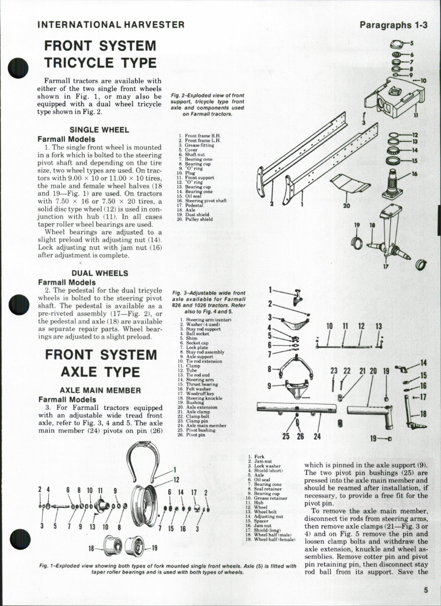
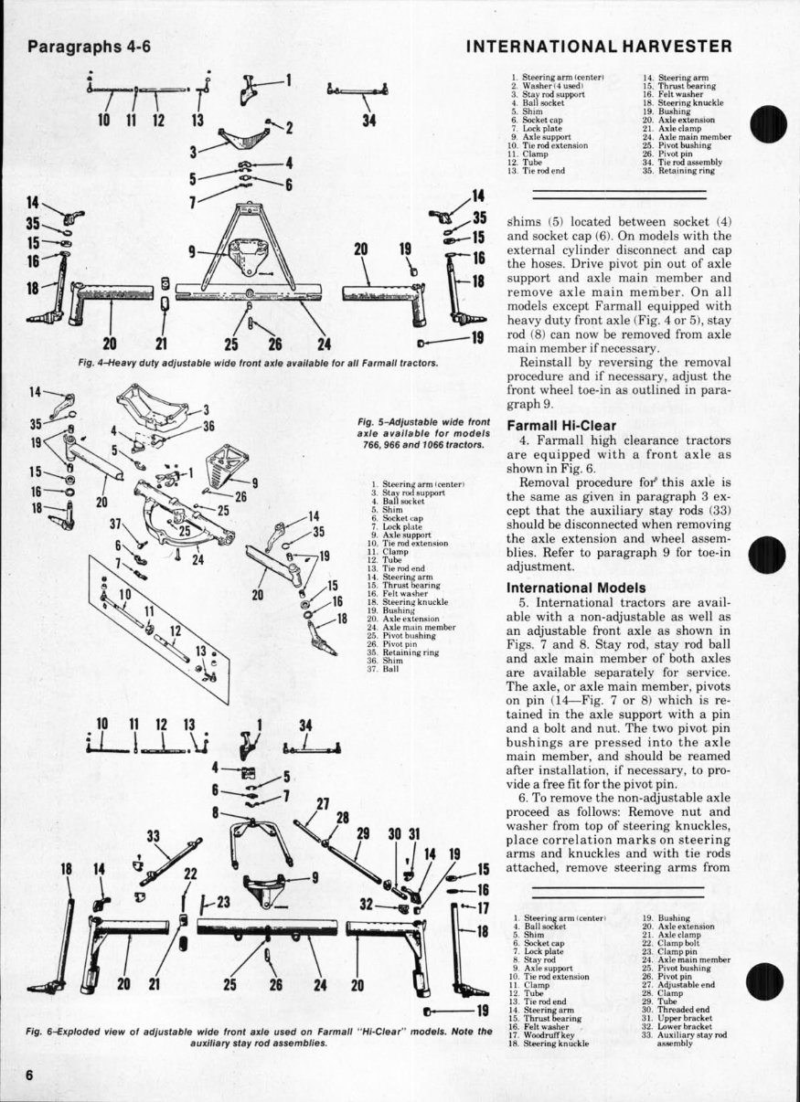
INTERNATIONAL HARVESTER FRONT SYSTEM TRICYCLE TYPE Paragraphs 1-3 5 Farmall tractors are available with either of the two single front wheels shown in Fig. 1, or may also be equipped with a dual wheel tricycle type shown in Fig. 2. SINGLE WHEEL Farmall Models 1. The single front wheel is mounted in a fork which is bolted to the steering pivot shaft and depending on the tire size, two wheel types are used. On trac- tors with 9.00 X 10 or 11.00 x 10 tires, the male and female wheel halves (18 and 19—Fig. 1) are used. On tractors with 7.50 X 16 or 7.50 x 20 tires, a solid disc type wheel (12) is used in con- junction with hub (11). In all cases taper roller wheel bearings are used. Wheel bearings are adjusted to a slight preload with adjusting nut (14). Lock adjusting nut with jam nut (16) after adjustment is complete. DUAL WHEELS Farmall Models 2. The pedestal for the dual tricycle wheels is bolted to the steering pivot shaft. The pedestal is available as a pre-riveted assembly (17—Fig. 2), or the pedestal and axle (18) are available as separate repair parts. Wheel bear- ings are adjusted to a slight preload. FRONT SYSTEM AXLE TYPE AXLE MAIN MEMBER Farmall Models 3. For Farmall tractors equipped with an adjustable wide tread front axle, refer to Fig. 3, 4 and 5. The axle main member (24) pivots on pin (26) Fig. 2-Exfiioded ¥lew of front support, tricyde type front axle and components used on FarmatI tractors. 1. Front frame R.H. 2. Front frame L.H. 3. Grease fitting 5. Cover 6. Shaft nut 7. Bearing cone 8. Bearing cup 9. "O"ring 10. Plug 11. Front support 12. "O"ring 13. Bearing cup 14. Bearing cone 15. Oil seal 16. Steering pivot shaft 17. Pedestal 18. Axle 19. Dust shield 20. Pulley shield Fig. 3-Adlustabie wide front axle availabie for Farmaif 826 and tO26 tractors. Refer also to Fig. 4 and 5. 1. Steering arm (center) 2. Washer (4 used) 3. Stay rod support 4. Ball socket 5. Shim 6. Socket cap 7. Lock plate 8. Stay rod assembly 9. Axle support 10. Tie rod extension 11. Clamp 12. Tube 13. Tie rod end 14. Steering arm 15. Thrust bearing 16. Felt washer 17. WoodrufTkey 18. Steering knuckle 19. Bushing 20. Axle extension 21. Axle clamp 22. Clamp bolt 23. Clamp pin 24. Axle main member 25. Pivot bushing 26. Pivot pin 25 26 24 1, Fork 2, Jam nut 3, Lock washer 4, Shield (short) 5, Axle 6, Oil seal 7, Bearing cone 8, Seal retainer 9, Bearing cup 10. Grease retainer 11. Hub 12. Wheel 13. Wheel bolt 14. Ac^justingnut 15. Spacer 16. Jam nut 17. Shield (long) 18. Wheel haln male) 19. Wheel half (female) fig, 1~Bxpioded view showing both types of fork mounted single front wheels. Axle (5) is fitted with taper roller bearings and is used with both types of wheels. which is pinned in the axle support (9). The two pivot pin bushings (25) are pressed into the axle main member and should be reamed after installation, if necessary, to provide a free fit for the pivot pin. To remove the axle main member, disconnect tie rods from steering arms, then remove axle clamps (21—Fig. 3 or 4) and on Fig. 5 remove the pin and loosen clamp bolts and withdraw the axle extension, knuckle and wheel as- semblies. Remove cotter pin and pivot pin retaining pin, then disconnect stay rod ball from its support. Save the
Paragraphs 4-6 INTERNATIONAL HARVESTER 20 21 19 Fig. 4-Heavy duty adjustable wide front axle available for ail Farmaii tractors. Fig. S-Adjustable wide frortt axle avaiiabie for modeis 766, 966 and 1066 tractors. 1. Steering arm (center) 3. Stay rocTsupport 4. Ball socket 5. Shim 6. Socket cap 7. Lock plate 9. Axle support 10. Tie rod extension 11. Clamp 12. Tube 13. Tie rod end 14. Steering arm 15. Thrust bearing 16. Felt washer 18. Steering knuckle 19. Bushing 20. Axle extension 24. Axle main member 25. Pivot bushing 26. Pivot pin 35. Retaining ring 36. Shim 37. Ball 10 11 12 13 1 34 ijL_l_I_.\J ^ A- 25 26 24 20 1. Steering arm (center) 2. Washer (4 used) 3. Stay rod support 4. Ball socket 5. Shim 6. Socket cap 7. Lock plate 9. Axle support 10. Tie rod extension U. Clamp 12. Tube 13. TierwJend 14. Steering arm 15. Thrust bearing 16. Felt washer 18. Steering knuckle 19. Bushing 20. Axle extension 21. Axle clamp 24. Axle main member 25. Pivot bushing 26. Pivot pin 34. Tie rod assembly 35. Retaining ring shims (5) located between socket (4) and socket cap (6). On models with the external cylinder disconnect and cap the hoses. Drive pivot pin out of axle support and axle main member and remove axle main member. On all models except Farmall equipped with heavy duty front axle (Fig. 4 or 5), stay rod (8) can now be removed from axle main member if necessary. Reinstall by reversing the removal procedure and if necessary, adjust the front wheel toe-in as outlined in para- graph 9. Farmall Hi-Clear 4. Farmall high clearance tractors are equipped with a front axle as shown in Fig. 6. Removal procedure for^ this axle is the same as given in paragraph 3 ex- cept that the auxiliary stay rods (33) should be disconnected when removing the axle extension and wheel assem- blies. Refer to paragraph 9 for toe-in adjustment. International Models 5. International tractors are avail- able with a non-adjustable as well as an adjustable front axle as shown in Figs. 7 and 8. Stay rod, stay rod ball and axle main member of both axles are available separately for service. The axle, or axle main member, pivots on pin (14—Fig. 7 or 8) which is re- tained in the axle support with a pin and a bolt and nut. The two pivot pin bushings are pressed into the axle main member, and should be reamed after installation, if necessary, to pro- vide a free fit for the pivot pin. 6. To remove the non-adjustable axle proceed as follows: Remove nut and washer from top of steering knuckles, place correlation marks on steering arms and knuckles and with tie rods attached, remove steering arms from Fig. 6-Exploded view of adjustabie wide front axie used on Farmaii "Hi-Ciear" modeis. Note the auxiiiary stay rod assemblies. 1. Steering arm (center) 4. Ball socket 5. Shim 6. Socket cap 7. Lock plate 8. Stay rod 9. Axle support 10. Tie rod extension 11. Clamp 12. Tube 13. Tie rod end 14. Steering arm 15. Thrust bearing 16. Felt washer 17. Woodruff key 18. Steering knuckle 19. Bushing 20. Axle extension 21. Axle clamp 22. Clamp bolt 23. Clamp pin 24. Axle main member 25. Pivot bushing 26. Pivot pin 27. Adjustable end 28. Clamp 29. Tube 30. Threaded end 31. Upper bracket 32. Lower bracket 33. Auxiliary stay rod assembly
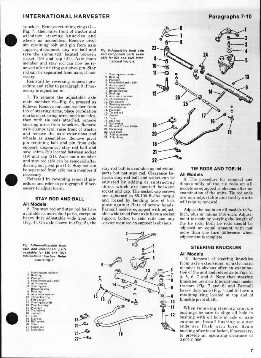
INTERNATIONAL HARVESTER Paragraphs 7-TO knuckles. Remove retaining rings (7— Fig. 7), then raise front of tractor and withdraw steering knuckles and wheels as assemblies. Remove pivot pin retaining bolt and pin from axle support, disconnect stay rod ball and save the shims (20) located between socket (19) and cap (21). Axle main member and stay rod can now be re- moved after driving out pivot pin. Stay rod can be separated from axle, if nec- essary. Reinstall by reversing removal pro- cedure and refer to paragraph 9 if nec- essary to adjust toe-in. 7. To remove the adjustable axle main member (9—Fig. 8), proceed as follows: Remove nut and washer from top of steering arms, place correlation marks on steering arms and knuckles, then with tie rods attached, remove steering arms from knuckles. Remove axle clamps (24), raise front of tractor and remove the axle extensions and wheels as assemblies. Remove pivot pin retaining bolt and pin from axle support, disconnect stay rod ball and save shims (20) located between socket (19) and cap (21). Axle main member and stay rod (18) can be removed after driving out pivot pin (14). Stay rod can be separated from axle main member if necessary. Reinstall by reversing removal pro- cedure and refer to paragraph 9 if nec- essary to adjust toe-in. STAY ROD AND BALL All Models 8. The stay rod and stay rod ball are available as individual parts, except on heavy duty adjustable wide front axle (Fig. 4). On axle shown in (Fig. 5), the Fig. S-Adfustabie front axie and component parts avaii- abie for 826 and 1026 inter- nationai tractors. Steering arm (center) Bushing Pivot pin Shim (0.010 and 0.020) Axle support Steering arm Retaining ring Bushing Axle main member Thrust bearing Felt washer Steering knuckle Pivot bushing Pivot pin Tie rod end Jam nut Tube Stay rod Ball socket Shim (0.010 and 0.020) Socket cap Lock plate Axle extension Axle clamp stay rod ball is available as individual parts but not stay rod. Clearance be- tween stay rod ball and socket can be adjusted by adding or subtracting shims which are located between socket and cap. The socket cap screws are tightened to 85-100 ft.-lbs. torque and locked by bending tabs of lock plate against flats of screw heads. Farmall models equipped with adjust- able wide tread front axle have a socket support bolted to side rails and any service required on support is obvious. Fig, axle 7~Non-adjustabie front and component parts avaiiabie for 826 and 1026 international tractors. Refer 1. 2. 3. 4. 5. 6. 7. 8. 9. 10. 11. 12. 13. 14. 15. 16. 17. 18. 19. 20. 21. 22. aiso to Fig. 8. Steering arm (center) Bushing Pivot pin Shim (0.010 and 0.020) Axle support Steering arm Retaining ring Bushing Axle main member Thrust bearing Felt washer Steering knuckle Pivot bushing Pivot pin Tie rod end Jam nut Tube Stay rod Ball socket Shim Socket cap Lock plate 19 tit ZU 21 22 TIE RODS AND TOE-IN All Models 9. The procedure for removal and disassembly of the tie rods on all models so equipped is obvious after an examination of the units. Tie rod ends are non-adjustable and faulty units will require renewal. Adjust the toe-in on all models to V4- inch, plus or minus 1/16-inch. Adjust- ment is made by varying the length of the tie rods. Both tie rods should be adjusted an equal amount with not more than one turn difference when adjustment is complete. STEERING KNUCKLES All Models 10. Removal of steering knuckles from axle extensions, or axle main member is obvious after an examina- tion of the unit and reference to Figs. 3, 4, 5, 6, 7 and 8. Note that steering knuckles used on International model tractors (Fig. 7 and 8) and Farmall heavy duty axle (Fig. 4 and 5) have a retaining ring located at top end of knuckle pivot shaft. When renewing steering knuckle bushings be sure to align oil hole in bushing with oil hole in axle or axle extension. Install bushing so outer ends are flush with bore. Ream bushing after installation, if necessary, to provide an operating clearance of 0.001-0.006.
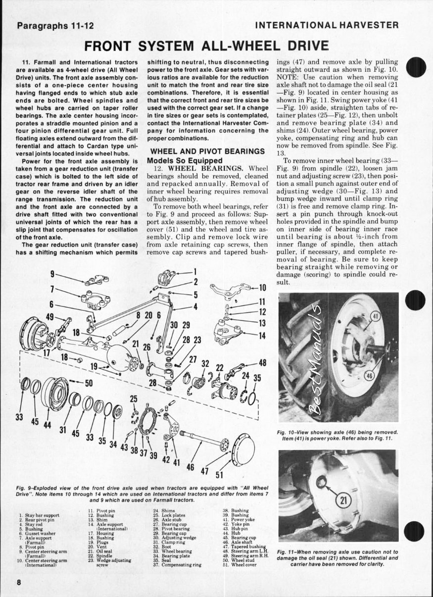
Paragraphs 11-12 INTERNATIONAL HARVESTER FRONT SYSTEM ALL-WHEEL DRIVE 11. Farmall and International tractors are available as 4-wheet drive (All Wheel Drive) units. The front axle assembly con- sists of a one-piece center housing having flanged ends to which stub axle ends are bolted. Wheel spindles and wheel hubs are carried on taper roller bearings. The axle center housing incor- porates a straddie mounted pinion and a four pinion differential gear unit. Full floating axles extend outward from the dif- ferential and attach to Cardan type uni- versal joints located inside wheel hubs. Power for the front axle assembly is taken from a gear reduction unit (transfer case) which is bolted to the ieft side of tractor rear frame and driven by an idler gear on the reverse idler shaft of the range transmission. The reduction unit and the front axle are connected by a drive shaft fitted with two conventional universal joints of which the rear has a slip joint that compensates for oscillation of the front axle. The gear reduction unit (transfer case) has a shifting mechanism which permits shifting to neutral, thus disconnecting power to the front axle. Gear sets with var- ious ratios are available for the reduction unit to match the front and rear tire size combinations. Therefore, it is essential that the correct front and rear tire sizes be used with the correct gear set. If a change in tire sizes or gear sets is contemplated, contact the International Harvester Com- pany for information concerning the proper combinations. WHEEL AND PIVOT BEARINGS Models So Equipped 12. WHEEL BEARINGS. Wheel bearings should be removed, cleaned and repacked annually. Removal of inner wheel bearing requires removal of hub assembly. To remove both wheel bearings, refer to Fig. 9 and proceed as follows: Sup- port axle assembly, then remove wheel cover (51) and the wheel and tire as- sembly. Clip and remove lock wire from axle retaining cap screws, then remove cap screws and tapered bush- Fig. 9-Exploded view of the front drive axie used when tractors are equipped with "AU Wheei Drive". Note items 10 through 14 which are used on international tractors and differ from items 7 and 9 which are used on Farmaii tractors. 1. Stay bar support 2. Rear pivot pin 4. Stay rod 5. Bushing 6. Gusset washer 7. Axle support (Farmall) 8. Pivot pin 9. Center steering arm (Farmain 10, Center steering arm (International) U. Pivot pin 12. Bushing 13. Shim 14. Axlesupi>ort (International) 17. Housing 18. Bushing 19. Plugs 20. Vent 21. Oil seal 22. Spindle 23. Wedge adjusting screw 24. Shims 25. Lock plates 26. Axle stub 27. Bearing cup 28. Pivot bearing 29. Bearing cap 30. Adjustmg wedge 31. Clamp ring 32. Boot 33. Wheel bearing 34. Bearing plate 35. Seal 37. Compensating ring 38. Bushing 39. Bushing 41. Power yoke 42. Yoke pin 43. Hub pin 44. Hub 45. Bearing cup 46. Axleshafl 47. Tapered bushing 48. Steering arm L.H. 49. Steering arm R.H, 50. Wheel stud 51. Wheel cover ings {47) and remove axle by pulling straight outward as shown in Fig. 10. NOTE: Use caution when removing axle shaft not to damage the oil seal (21 —Fig. 9) located in center housing as shown in Fig. 11. Swing power yoke (41 —Fig. 10) aside, straighten tabs of re- tainer plates (25—Fig. 12), then unbolt and remove bearing plate (34) and shims (24). Outer wheel bearing, power yoke, compensating ring and hub can now be removed from spindle. See Fig. 13. To remove inner wheel bearing (33— Fig. 9) from spindle (22), loosen jam nut and adjusting screw (23), then posi- tion a small punch against outer end of adjusting wedge (30—Fig. 13) and bump wedge inward until clamp ring (31) is free and remove clamp ring. In- sert a pin punch through knock-out holes provided in the spindle and bump on inner side of bearing inner race until bearing is about V2-inch from inner flange of spindle, then attach puller, if necessary, and complete re- moval of bearing. Be sure to keep bearing straight while removing or damage (scoring) to spindle could re- sult. Fig. 10~View showing axle (46) being removed. Item (41} is power yoke. Refer also to Fig. 11. Fig. 11-When removing axle use caution not to damage the oil seai (21) shown. Differential and carrier have been removed for clarity.
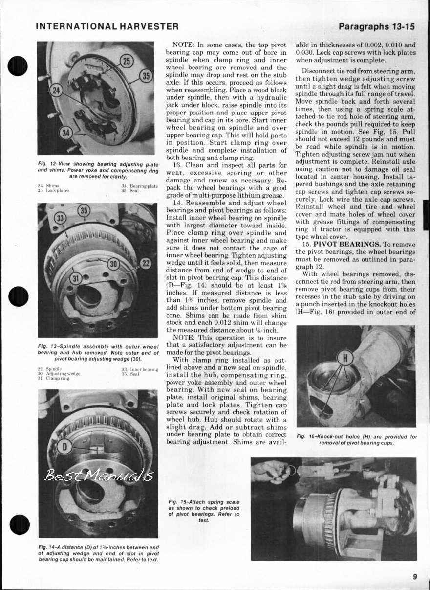
INTERNATIONAL HARVESTER Paragraphs 13-15 Fig. 12-View showing bearing adjusting plate and shims. Power yoke and compensating ring are removed for darity. 24. Shims 25. Lock plates 34. Bearing plate 35. Seal Fig. 13-SpinfHe assembly with outer wheei bearing and hub removed. Note outer end of pivot bearing adjusting wedge (30). 22. Spindle 30. Adjusting wedge 31. Clamp ring 33. Inner bearing 35. Seal NOTE: In some cases, the top pivot bearing cap may come out of bore in spindle when clamp ring and inner wheel bearing are removed and the spindle may drop and rest on the stub axle. If this occurs, proceed as follows when reassembling. Place a wood block under spindle, then with a hydraulic jack under block, raise spindle into its proper position and place upper pivot bearing and cap in its bore. Start inner wheel bearing on spindle and over upper bearing cap. This will hold parts in position. Start clamp ring over spindle and complete installation of both bearing and clamp ring. 13. Clean and inspect all parts for wear, excessive scoring or other damage and renew as necessary. Re- pack the wheel bearings with a good grade of multi-purpose lithium grease. 14. Reassemble and adjust wheel bearings and pivot bearings as follows: Install inner wheel bearing on spindle with largest diameter toward inside. Place clamp ring over spindle and against inner wheel bearing and make sure it does not contact the cage of inner wheel bearing. Tighten adjusting wedge until it feels solid, then measure distance from end of wedge to end of slot in pivot bearing cap. This distance (D—Fig. 14) should be at least 1% inches. If measured distance is less than 1% inches, remove spindle and add shims under bottom pivot bearing cone. Shims can be made from shim stock and each 0.012 shim will change the measured distance about Vs-inch. NOTE: This operation is to insure that a satisfactory adjustment can be made for the pivot bearings. With clamp ring installed as out- lined above and a new seal on spindle, install the hub, compensating ring, power yoke assembly and outer wheel bearing. With new seal on bearing plate, install original shims, bearing plate and lock plates. Tighten cap screws securely and check rotation of wheel hub. Hub should rotate with a slight drag. Add or subtract shims under bearing plate to obtain correct bearing adjustment. Shims are avail- able in thicknesses of 0.002, 0.010 and 0.030. Lock cap screws with lock plates when adjustment is complete. Disconnect tie rod from steering arm, then tighten wedge adjusting screw until a slight drag is felt when moving spindle through its full range of travel. Move spindle back and forth several times, then using a spring scale at- tached to tie rod hole of steering arm, check the pounds pull required to keep spindle in motion. See Fig. 15. Pull should not exceed 12 pounds and must be read while spindle is in motion. Tighten adjusting screw jam nut when adjustment is complete. Reinstall axle using caution not to damage oil seal located in center housing. Install ta- pered bushings and the axle retaining cap screws and tighten cap screws se- curely. Lock wire the axle cap screws. Reinstall wheel and tire and wheel cover and mate holes of wheel cover with grease fittings of compensating ring if tractor is equipped with this type wheel cover. 15. PIVOT BEARINGS. To remove the pivot bearings, the wheel bearings must be removed as outlined in para- graph 12. With wheel bearings removed, dis- connect tie rod from steering arm, then remove pivot bearing cups from their recesses in the stub axle by driving on a punch inserted in the knockout holes (H—Fig. 16) provided in outer end of Fig. 16-Knock-out hoies (H) are provided for removal of pivot bearing cups. Fig. 15-Attach spring scale as shown to check preload of pivot bearings. Refer to text. Fig. 14-A distance (D) of 1 ^/9-inches between end of adjusting wedge and end of slot in pivot bearing cap should be maintained. Refer to text.
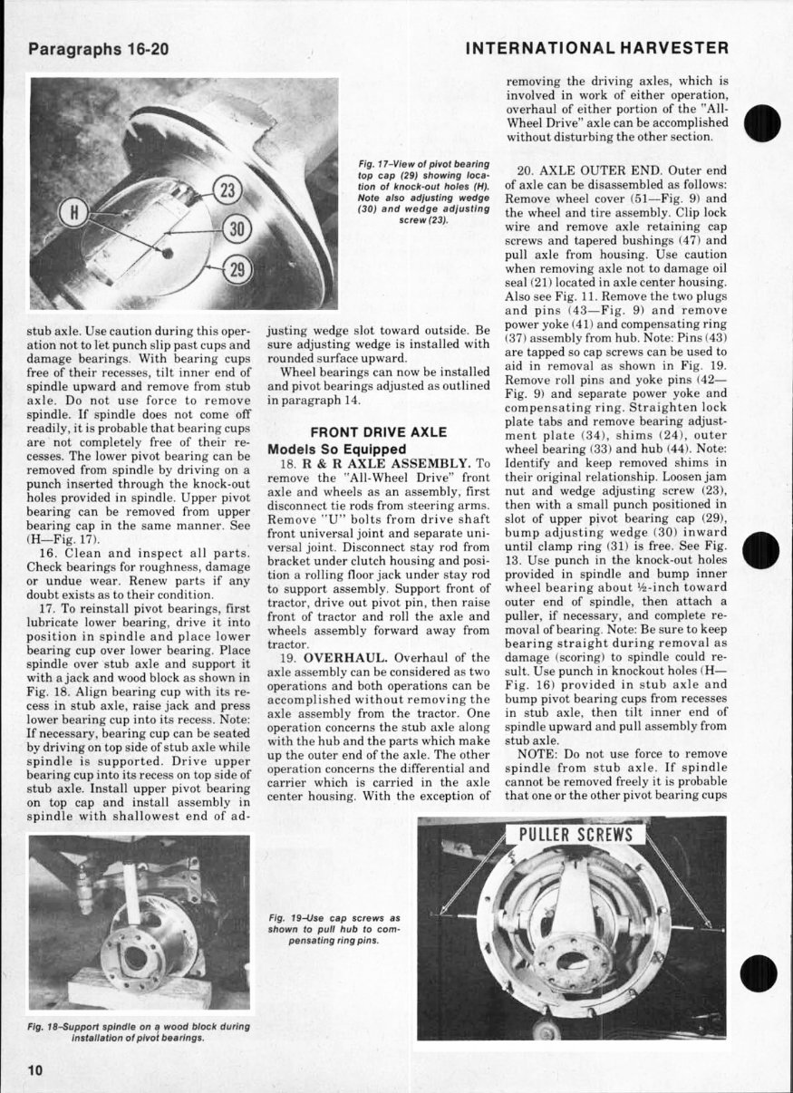
Paragraphs 16-20 INTERNATIONAL HARVESTER Fig. 17-View of pivot bearing top cap (29) showing loca- tion of knock'Out holes (H). Note aiso adjusting wedge (30) and wedge adjusting screw (23). stub axle. Use caution during this oper- ation not to list punch slip past cups and damage bearings. With bearing cups free of their recesses, tilt inner end of spindle upward and remove from stub axle. Do not use force to remove spindle. If spindle does not come off readily, it is probable that bearing cups are not completely free of their re- cesses. The lower pivot bearing can be removed from spindle by driving on a punch inserted through the knock-out holes provided in spindle. Upper pivot bearing can be removed from upper bearing cap in the same manner. See (H—Fig. 17). 16. Clean and inspect all parts. Check bearings for roughness, damage or undue wear. Renew parts if any doubt exists as to their condition. 17. To reinstall pivot bearings, first lubricate lower bearing, drive it into position in spindle and place lower bearing cup over lower bearing. Place spindle over stub axle and support it with a jack and wood block as shown in Fig. 18. Align bearing cup with its re- cess in stub axle, raise jack and press lower bearing cup into its recess. Note: If necessary, bearing cup can be seated by driving on top side of stub axle while spindle is supported. Drive upper bearing cup into its recess on top side of stub axle. Install upper pivot bearing on top cap and install assembly in spindle with shallowest end of ad- justing wedge slot toward outside. Be sure adjusting wedge is installed with rounded surface upward. Wheel bearings can now be installed and pivot bearings adjusted as outlined in paragraph 14. FRONT DRIVE AXLE Models So Equipped 18. R & R AXLE ASSEMBLY. To remove the "All-Wheel Drive" front axle and wheels as an assembly, first disconnect tie rods from steering arms. Remove ''U" bolts from drive shaft front universal joint and separate uni- versal joint. Disconnect stay rod from bracket under clutch housing and posi- tion a rolling floor jack under stay rod to support assembly. Support front of tractor, drive out pivot pin, then raise front of tractor and roll the axle and wheels assembly forward away from tractor. 19. OVERHAUL. Overhaul of the axle assembly can be considered as two operations and both operations can be accomplished without removing the axle assembly from the tractor. One operation concerns the stub axle along with the hub and the parts which make up the outer end of the axle. The other operation concerns the differential and carrier which is carried in the axle center housing. With the exception of removing the driving axles, which is involved in work of either operation, overhaul of either portion of the "All- Wheel Drive" axle can be accomplished without disturbing the other section. 20. AXLE OUTER END. Outer end of axle can be disassembled as follows: Remove wheel cover (51—Fig. 9) and the wheel and tire assembly. Clip lock wire and remove axle retaining cap screws and tapered bushings (47) and pull axle from housing. Use caution when removing axle not to damage oil seal (21) located in axle center housing. Also see Fig. 11. Remove the two plugs and pins (43—Fig. 9) and remove power yoke (41) and compensating ring (37) assembly from hub. Note: Pins (43) are tapped so cap screws can be used to aid in removal as shown in Fig. 19. Remove roll pins and yoke pins (42— Fig. 9) and separate power yoke and compensating ring. Straighten lock plate tabs and remove bearing adjust- ment plate (34), shims (24), outer wheel bearing (33) and hub (44). Note: Identify and keep removed shims in their original relationship. Loosen jam nut and wedge adjusting screw (23), then with a small punch positioned in slot of upper pivot bearing cap (29), bump adjusting wedge (30) inward until clamp ring (31) is free. See Fig. 13. Use punch in the knock-out holes provided in spindle and bump inner wheel bearing about y2-inch toward outer end of spindle, then attach a puller, if necessary, and complete re- moval of bearing. Note: Be sure to keep bearing straight during removal as damage (scoring) to spindle could re- sult. Use punch in knockout holes (H— Fig. 16) provided in stub axle and bump pivot bearing cups from recesses in stub axle, then tilt inner end of spindle upward and pull assembly from stub axle. NOTE: Do not use force to remove spindle from stub axle. If spindle cannot be removed freely it is probable that one or the other pivot bearing cups Fig. 19-Use cap screws as shown to pull hub to com- pensating ring pins. Fig. IB-Support spindle on a wood block during instailation of pivot bearings. 10
You're Reading a Preview
What's Included?
Lifetime Access
Fast Download Speeds
Online & Offline Access
Access PDF Contents & Bookmarks
Full Search Facility
Print one or all pages of your manual
$31.99
International Harvester 966 Tractor Repair Service Manual
This repair service manual workshop is designed to cover the repair and overhaul procedures for International Harvester 966 Tractor cars. It is suitable for both professional mechanics and DIY enthusiasts. The manual includes instructions on various components such as tune-ups, maintenance, removal and installation procedures, assemblies and disassemblies, fuel system, ignition, lubrication system, exhaust, electrical system, body, and more extensive repairs involving engine and transmission disassembly. It also provides information and procedures for routine maintenance, servicing, and diagnostic and repair procedures to follow when trouble occurs.
For those intending to do maintenance and repair on their International Harvester 966 Tractor, it is essential to use safety equipment and observe safety precautions. The manual also refers to special tools that are recommended or required to accomplish adjustments or repairs, often identified by their International Harvester 966 Tractor special tool number and illustrated.
This electronic delivery via email is available in English and is printable. The manual aims to provide the most reliable information and includes many of the specifications and procedures available in an authorized International Harvester 966 Tractor dealer service department.
General maintenance tags for WSMBEST workshop service manuals include air cleaner element renewal, battery terminal check, brake hydraulic fluid renewal, choke adjustment check, engine coolant renewal, exhaust system check, fluid level checks, front and rear brake pad/shoe check, gearbox oil level check, road test, spark plug check, timing belt renewal, tyre checks, and more.
Reviews
Q&A
Recently Viewed
5,521,897Happy Clients
2,594,462eManuals
1,120,453Trusted Sellers
15Years in Business
Price:
Actual Price:
International Harvester 966 Tractor Repair Service Manual




 Lifetime Access




