SHOP MANUAL INTERNATIONAL HARVESTER SERIES 330.340·504.2504 Engine serial number is stamped on left side of engine crankcase. Engine serial number will be pre· ceeded by engine model number. Suffix letters to engine serial number are as follows: U. High Altitude Engine V. Exhaust Valve Rotators Tractor serial number is stamped on name plate attached to right side of clutch housing. Suffix letters to tractor serial numbers indicate following attachments: J. Rockford Clutch P. Independent PTO Drive R. "T orque-Amplifier" With Provision for Transmission Driven PTO S. "Torque Amplifier" With Provision for Independent PTO T. Cotton Picker Mounting Attachment (Low Drum) U. High-Altitude V. Exhaust Valve Rotators W. Forward and Reverse Drive X. High Speed Low and Reverse Y. Hydraulic Power Supply (12 gpm pump) Z. Hydraulic Power Supply (17 gpm pump) FF. Hydraulic Power Supply (4.5 gpm pump) GG. Hydraulic Powe r Supply (7.0 gpm pump) I ND E X (By Starting Paragraph) Series 330 BELT PULLE1r . .. ............ 167 BRAKES ........ . .. . ........ 165 CARBURETOR (Gaa) . ... .. ... 120 CARBURETOR (LP·Gas) . ..•. . CLUTCH. ENGINE . .. ........ 133 COOLING SYSTEM Radiator . .............. .. 117 VVater PUInP ... ... .. .. .... 118 DIESEL FUEL SYSTEM Injection Pump a nd Drive . . . Nozzles . ........ . ....... . System Checks .... ...... . DIFFERENTIAL . . . .... .... '. . . 132 DIRECTION REVERSER .. . .. . ENGINE Balancer ............... . . Cam Foll ow ers ....... .. .. . 52 Camshaft ... .... ... .. .. ... 58 Connecting Rod & Bearings 64 Cra nks ha ft ... . ............ 66 Cyl inder Head . ........ . .. 49 Engine Remova l . . . . . . . . . . . 48 Flywheel ...... .. ... . ... .. 68 Ignition Timing .. . .. ... ... 129 Ma in Bea rings . .... ... . .. . 66 Oil Pump . .. .. .. .......... 69 Oil Cooler ........ . .... .. . Piston & Rings ........ •. .. 60 Piston Pins . . . ........ .... 63 Rear Oil Se al .. .. ...... .. . 67 Rocker Arms . . . . . . . . . . . . . . 53 Timing Ge ar Cov er . . . . . . . . 56 Timing Gea rs .. ........... 57 Valv es and Seat s.. ... . .... 50 Valv e Guid es & Springs . . . . 51 Valve Timing ... . '.' . . . . . . . 55 FINAL DRIVE Bull Gears ....... . .. ..... 163 2 Series 340 167 165 120 133 11 7 118 113 107 99 132 146 90 52.75 58.85 64 .92 66. 93 49. 72 47.70 68.96 129 66.93 69.97 60.88 63.89 67.95 53. 76 56.80 57.81 50.73 51. 74 55. 79 163 Series 504. 2504 167 165 120 119A 133 117 118 113 107 99 132 146 90 52.75 58.85 64.92 66.93 49.72 47A. 48. 70A. 71 68.96 129 66 . 93 69.97 98A 62A.88 63. 89 67.95 53. 76 56.80 57.81 50.73 51. 74 55. 79 163 FINAL DRIVE CONT. Bull Pinions ... .. ......... 162 VVheel Axle Shaft . . . . . . . . . . 164 FRONT SYSTEM Axle Main Member. . . . . . . . . 3 Steering Knuckles .. . ... . .. 10 Tie Rods and Drag Links. . . 7 Tricycle Type ...... ...... . GOVERNOR (NON·DIESEL) .. 1I6A HYDRAULIC SYSTEM Control Valves .. ... . ...... 199 Lubrication .. .......... ... 184 Pump .................... 192 Regulator & Safety Valve . .. 201 System Adjustments . ..... . Testing .. ... .. .......... .. 187 Trouble Shooting . ... .... .. 191 POVVER STEERING SYSTEM Cylinder .... . ... .. . ... . .. 37 Flow Control & Relief Valve 27 Lubrication and Bleeding .. 25 Power Unit .............. . Pump .. ................. . Rotary Valve .. .. ........ . Steering Gear . .. .. ........ 39 Steering Valves ..... . .. . .. 35 Testing . ... ... .... . .. . ... . Trouble Shooting ..... .... • Pilot Valve .......... • .... Hand PUInp ........ .. .. .. . POVVER TAKE·OFF Adjustments (Clutch Type) ........... 171 ( Planetary Type) ........ 170 O verhaul . (Clutch Type) .... ... .... 179 (Planetary Type) . . ...... 174 STEERING. MANUAL ....... . 13 TORQUE AMPLIFIER Clutch Adjustment . . . . . . . .. 141 Clutch Overhaul. . . . . . . . . .. 144 Planetary Unit .......... .. 145 TRANSMISSION OVERHAUL .. 151 162 164 3 10 7 1 116A 199 185 192 201 187 191 37 27 25 34 30 38.39 35 171 170 179 174 12 141 144 145 151 162 164 3 10 7 1 lI6A 230 210 220 214 213 212 37A 29J 26A.26B 34 30 35A 38 29C 26C 46A 45 171 179 12 141 1 44 145 151
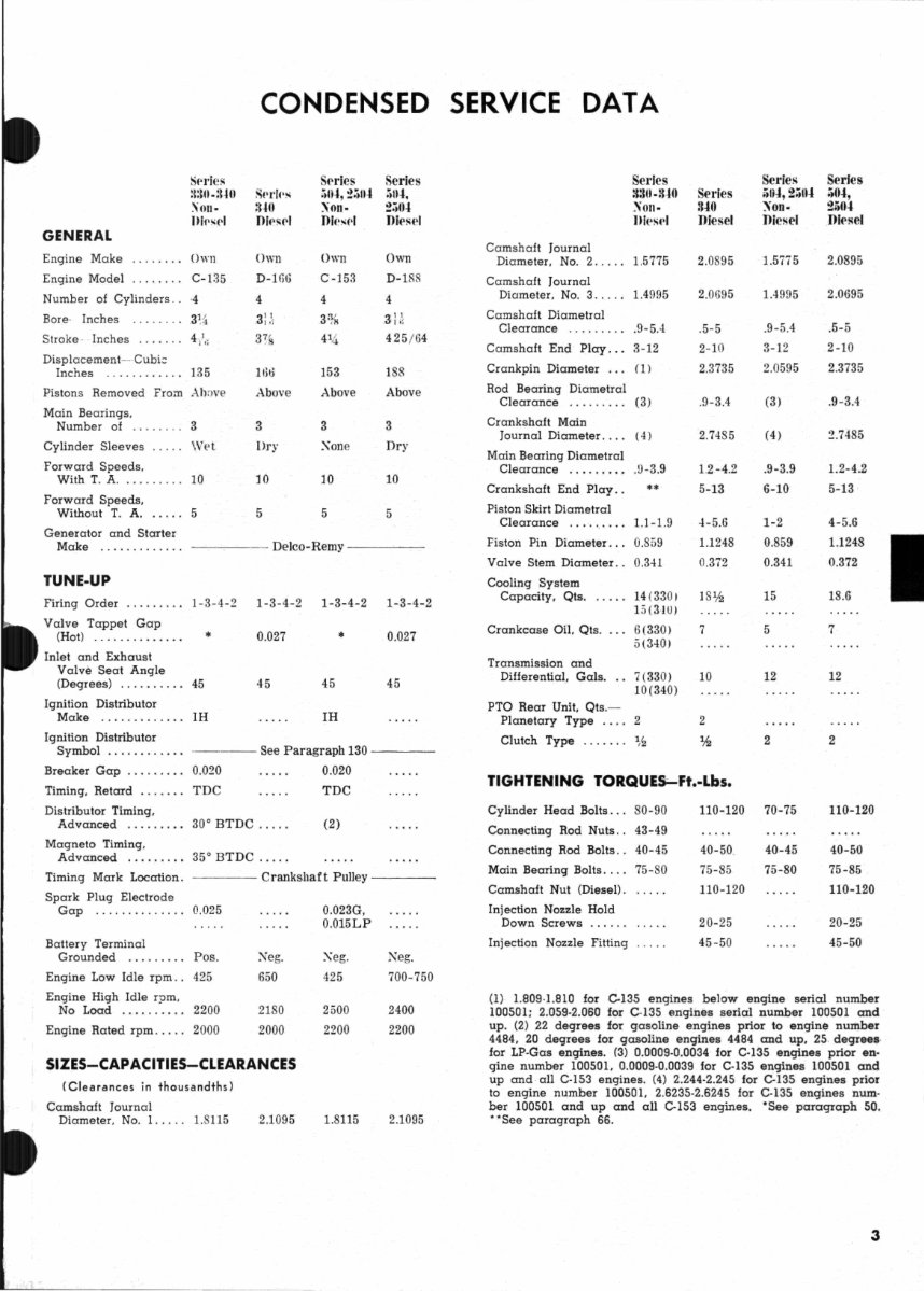
CONDENSED SERVICE DATA GENERAL Engine Make Engine Model SpJ'ics lI:\U.:WI \UII' J1irsrJ OWII C' -13 ;; Number or Cylin ders.. -1 Bore· Inches ... ..... :) % Stroke· . Inches Displacement--·Cubi= Inches ... . ........ 133 Pistons Removed From AhDve Main Be arings. Number of ... 3 Cylinder Sleeves Wet Forward Speeds. With T. A .......... 10 Forward Speeds . Without T. A. .. ... .) Generator and Starter Sf'rlf'S :UO OipsrJ Own 1)-166 ·1 11l1l Above 3 Dr y JO ;) Srl'ies :'Ii",:!:;"" \on· Oic~rl 0\\, 11 C-J;)3 -l 133 Above 3 .:\one ]0 5 Series :;" ... :!:.O .. Oiesel Own /1-1 88 188 Above 3 Dry 10 5 Make .. .. ........ . ----.-- De lco-Remy - -- -- TUNE-UP Firing Order ..... ... . 1-3-4 -2 1-3-4-2 1-3-4-2 1-3-4-2 Valve Tappet Gap (Hot) ... . ......... .• 0.027 • 0.027 Inlet and Exhaust Val ve Seat Angle ( Degrees) . . ...... .. ~:; 45 45 45 Ignition Distributor Make . ............ 1H IH Ignition Distributor Symbol .. ... . ..... . ----- See Paragraph 130 ---- Breaker Gap ... .. .. .. 0.020 0.020 Timing. Retard ....... TDC TDC Distributor Timing. Advanced .. ....... 30° BTDC . ... . (2) Magneto Timing. Advanced . ... . .... 35° BTDC .. .. . Timing Mark Location . Spark Plug Electrode -- - - Crankshaft Pulley ---- Gap .............. 0.025 Battery Terminal Grounded . .. .. .... Pos. Engine Low Idle rpm .. 425 Engine High Idle rpm. :\'eg. 650 No Load ..... . .... ~:?OJ 2180 Engine Rated rpm . . . . . 2000 2000 SIZES-CAPACITIES-CLEARANCES (Clearances in thousandths) Camshaft Journal Diameter . No .1 .... . 1.8115 2.1095 0.023G. 0.015LP .:\eg. 425 2500 2200 1.8115 Neg. 700-750 2400 2200 2.1095 Camshaft Journal Series :13U·8 .. 0 \011. ])I('srl Di ameter. No.2 ..... 1.5 7';5 Ca mshaft Journal Diameter. No. 3 . . . .. 1.· 19 9::> Camshaft Diametral Clearance ........ . .9 -5A Camshaft End Play ... 3-12 Crankpin Diameter ... (1 ) Rod Bearing Diametral Clearance ...... ... (3 ) Crankshaft Main Journal Diameter. . .. (4) Main Bearing Diametral Clearance . ......... 9-3 .9 Crankshaft End Play .. .. Piston Skirt Diametral Clearance .... .. ... . 1.1-1.9 Fiston Pin Diameter... 0.859 Valve Stem Diameter .. 0.341 Cooling System Capacity. Qts . .. . .. 14(330) 15(310) Crankcase Oil. Qts . 6(330) Transmission and Differential. Gals. PTO Rear Unit. Qts.- 5{3~0) 7(330) 10(340) Series 8 .. 0 Diesel 2.0895 2.0695 .5-5 2-10 2.373:; .9-3.4 2.7485 1.~-4.2 5- 13 -l- 5.S 1.1248 0. 372 ]8% 7 10 Planetary Type . ... 2 2 Clutch Type .. ... .. % "h TIGHTENING TORQUE$;-Ft.-Lbs. Series ;)U",2;;"" \on· Diesel 1.4995 .9-5.4 3-12 2.0ii9" (3) ( 4 ) .9-3.9 6-10 1-2 0.859 0.341 15 5 12 2 Cylinder Head Bolts. .. 80-90 Connecting Rod Nuts .. 43-49 Connecting Rod Bolts .. 40-45 Main Bearing Bolts .... 75-80 Camshaft Nut (Diesel). Injection Nozzle Hold 110-120 70-75 Down Screws Injection Nozzle Fitting 40-50. 75-85 .110-120 20-25 43-50 40-45 75- 80 Series ;;0 .. , 2;)0" Dit'sel 2.0895 2.0695 .5-5 2-10 2.3735 .9-3.4 2.7485 J.:!-4.2 5-13 4- 5.6 1.1248 0.372 18.6 7 12 2 110-120 40-50 75-85 110-120 20-25 45-50 (I) 1.809-1.810 for C-135 engines below engine serial number 100501; 2.059-2.060 for C-135 angines serial number 100501 and up. (2) 22 degrees for gasoline engines prior to engine number 4484. 20 degrees for gasoline engines 4484 and up. 25. degrees, for LP-Gas engines. (3) 0.0009·0.0034 for C-135 engines prior en- gine number 100501. 0.0009·0.0039 for C·135 engines 100501 and up and all C-153 engines . (4) 2.244-2.245 for C·135 engines prior to engine number 100501. 2.6235·2.6245 for C·135 engines num· ber 100501 and up and all C-153 engines. 'See paragraph 50. "See paragraph 66. 3
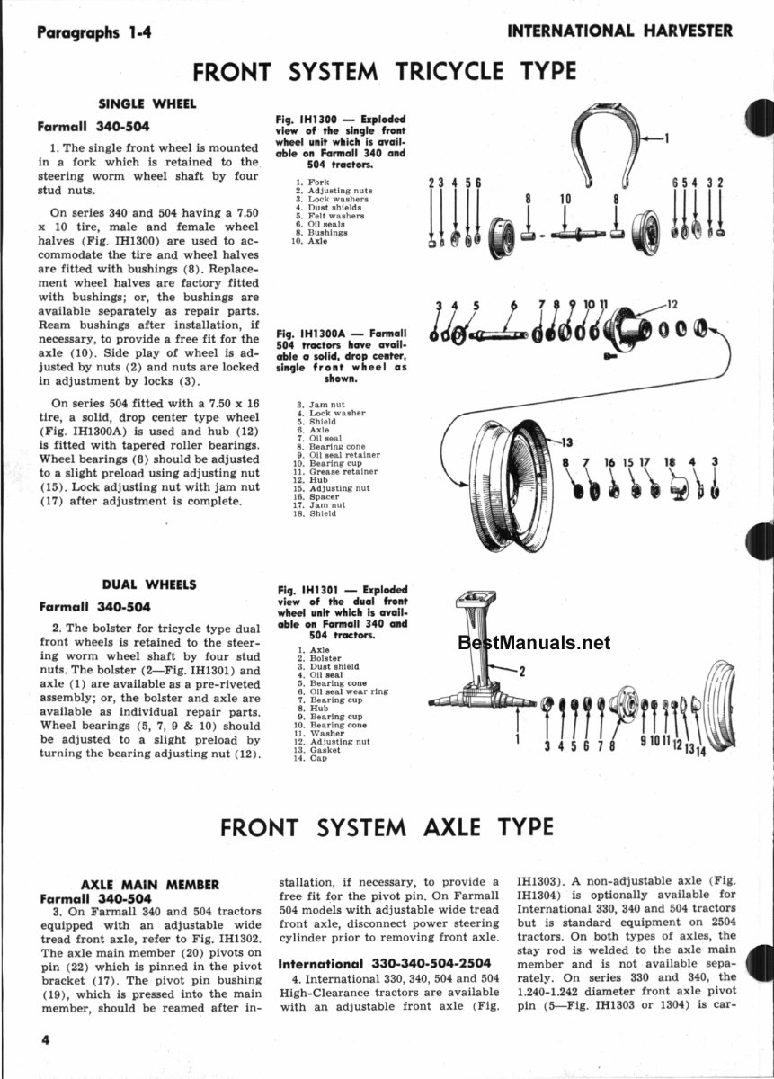
Paragraphs 1.4 INTERNATIONAL HARVESTER FRONT SYSTEM TRICYCLE TYPE SINGLE WHEEL Farmall 340· 504 1. The s ingle fr ont w he el is mounted in a f ork which is retained to the , steeri ng worm wheel sh aft by four stud nut.<;; . On series 340 and 504 having a 7.50 x 10 tir e, male and female wheel halves (Fig. IH1300) are used to ac- commodate the tire and wheel halves are fi tted with bushings (8 ). Replace- ment wheel halves are factory fitted with b ush i ngs ; or, the bushings are availabl e separately as repair parts . Ream bushings after installation, if necessary, to provide a free fit for the axle (10 ). Side play of wheel is ad- justed by nuts ( 2) and nuts are locked in adjustment by locks ( 3). On series 504 fitted with a 7.50 x 16 tire , a solid, drop center type wheel ( Fig. IH1300A) is used and hub (12) is fitted with tapered roller bearings . Wheel bearings (8) should be adjusted to a slight preload using adjusting nut (15). Lock adjusting nut with jam nut (17 ) after adj ustment is complete. DUAL WHEELS Farmall 340·504 2. The bol ster for tri cycle type dual front wheels is retaine d to the steer- ing worm wheel shaft by four stud nuts . The bolster (2- F ig. IH1301 ) and axle (1) are availab le as a pre-riveted assembly ; or , the bolster and axle are available as individual repair parts. Whe el beari ngs (5, 7, 9 & 10 ) should be adjusted to a slight preload by turni ng the bearing adjusting nut (12 ) . Fig. IHUOO - Exploded view of the single front wheel unit which is avail- able on Farmall 340 and 504 tractors. 1. Fork 2. Ad ju sting nu ts 3. Lock washers 4. Dust shiel ds 5. Felt washers 6. 011 seals 8. Bush ings 10. Axle Fig. IH1300A - Farmall 504 tractors have avail- able 0 solid. drop center. single front whee l as shown. 3. J am nut 4. Lock washer 5. Shiel d 6. Axle 7. Oll s",,1 8. Bearing cone 9. 011 seal retainer 10. Bearing cup 11 . Gr ease r etainer 12. H ub 15. Ad justing nut 16. S pacer 17. J am nut 18. Shield Fig. IH1301 - Exploded view of the dual front wheel unit which Is avail- able on Farmall 340 and 504 tractors. 1. Axle 2. Bol ster 3. Du st shield 4. 011 .eal 5. Bearing cone 6. 011 seal wear r ing 7. Bearing cup 8. Hu b 9. Bearing c up 10. Beari ng cone 11 . Washe r 12 . Adjusting nut 13. Gas ket 14. Cap lU ll L.Ll lr II Jjcl~JJJJ~'(;to'2 Q .. .i 1111 345678 FRONT SYSTEM AXLE TYPE AXLE MAIN MEMBER Farmall 340·504 3. On Farmall 340 and 504 tractors equipped with an a djust a ble wi de tread front axle, refer to Fig . IH1302. The axle main member (20) pivots on pin ( 22 ) which is pinned in the pivot br acket (17 ). The pivot pin bushing (19), whi ch is pressed into the main member, should be reamed af ter in- 4 stallation , if necessary, to prov i de a free fit ~or the p ivot pin . On Farmall 504 models with adju stable wide tread front ax le, disconnect power steering cylinder prior to remo v ing f ro nt axl e. International 330·340·504·2504 4. International 330, 340, 504 and 504 High-Clearance tractors are available with an adjustable front axle ( Fig. IHI303 ). A non-adjus ta bl e axle (Fig. IH1304) is optionall y a vaila b le f or Internationa l 330, 340 and 504 tr actors but is standard equipment on 2504 tr actors. On both types of axles, the stay rod is welded to th e axl e m ain member and is not ava il a bl e se pa - rat ely. On series 330 and 340, the 1.240-1.242 diameter f ro nt axl e pi v ot pin (5-Fig. IH1303 or 1304) is car-
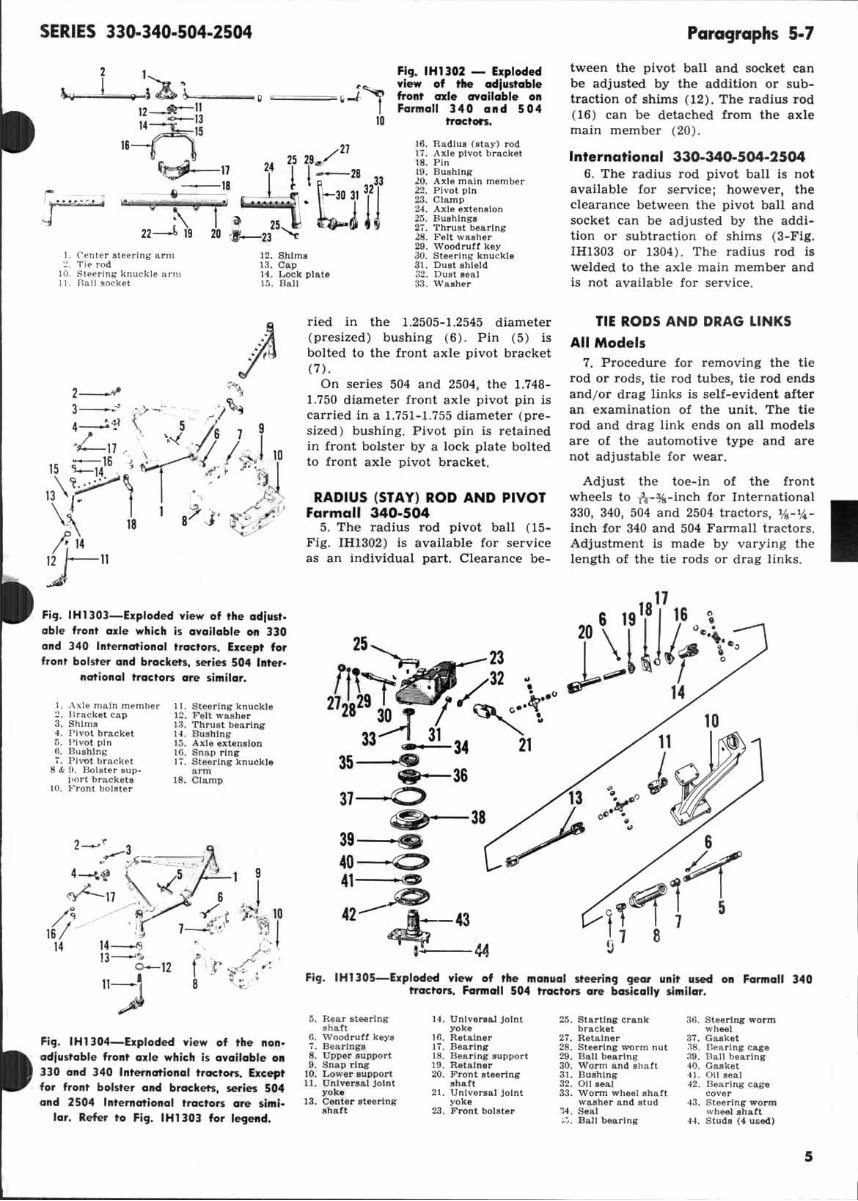
SERIES 33().340-504-2504 • ==' ~l' " Fig. IHIl02 - E.,loded .Ie. of the ocIIII"ab .. front cn:le crlolloble on Formol! 340 ond 504 lTocton. 16. nadluo (OtIY) rod 17 . Axle plyot br .. eket 18. Pin 19. Buohlng lO. Axle m .. ln membf!r 22. Ph·o ! pi n 23. Clamp 2-1. Allie ulen,lon ~. BUlhlnSI 21. Thru.t bf!lrlng ZII . ~'elt 'N .. h, r Paragraphs 5-7 tween the pivot ball and socket can be ad justed by the addiUon or s ub- t raction of s hims ( 12 ). The radius rOd (16) can be detached from the axle ma in member (20). International 330.340-504·2504 l. Conle r IIL .... ln ll urn TI~ rod 12. Shim. 20. Woadrurt key 3(1. Sl eering knuc kle 6. The radius rod pivot ball Is not available Cor service; however, the clearance be tw een the pivot ball an d socke t can be adjusted by the add i- tion or subt r action of shims (3 ·Ft,. IH1303 or 1304). The radius rod Is welded to the axle main member and Is not available for service. 13. e ll" 31. Ou.t Ihleld 10. ~'urlnl: knuckle nrm II. nan .ock. t 14. Lock pl&l. L~. Ban 32. DUll .... 1 33. W .. h~r Fi9 . IHllOl_hploded vi ew of 'he adi"'" able front axle wllieh is availabl e 011 no and 3.(0 Inte rnational t,oc'OMI. be e p' for fr ail' bolster alld brock ,"s, series 504 Int er· nat i onal tractors ore similar. I. ,\,111 main member ~. Hr. cket cap 3. Shlnl~ 4. Pivot br.cht ~. I'lvOI pin 6, nll.hlM!: 7. 1'1>"01 brack~1 8 '", . 13011l1e. AUp_ 1"'" braekot" 10. ~'rQn' bOla tor 11 . 8tH.!na- knuckle l~. Felt w ..... hu 13. ThtU ll t beanl\¥ 14. Ilullhlnll' 1 ~. A~I. utan.lon ilL 8n ap rlnl' I;. SIM,lnlf knuekl. .~ 18. Cram p Fl ", . IHl304-hploded view of the 11011 ' adlu st abl e front oxle whieh is available 011 llD and 340 Jllten\ationol tractors. bcept f or frail' b olster alld bro<:kets, 5efies 504 and 2504 International "_'01'$ ore simi- lar. Refef to Fig. IHUO] for le<Jilfld . ried in the 1.2505- 1.2545 diamete r ( presized ) bushing ( 6) . Pin (5) is bolted to the front ax le pivot bracket (7 ). On se ries 504 and 2504, the 1.748- 1.750 diameter front axle pivot pin is car ried in a 1.751-1.755 di amete r ( pre. sized) bushing. Pivot pin is retained in Cront bolster by a lock plate bolted to front axle pivot bracke t. RADIUS (STAY) ROD AND PIVOT Farmall 340·504 5. The radius rod pivot ball ( 15 - Fig. IH1 302) Is available for ser vice as an Indiv idu al part . Clearance be- TIE RODS AND DRAG LINKS All Models 7. Procedur e Cor removing the ti e rod or rods, tie rod tubes, tie rod ends and/or drag li nks is self-evident aft er an examination of the unit. The ti e rod and drag link ends on all models are of the automotive type and are not adjustable Cor wear. Adjust the toe-In oC the fr ont wh ee ls to h -%·Inch f or I nternationa l I 330, 340, 504 and 2504 tractors, %- t,4~ inch for 340 and 504 F annall tractors . Adju s tment is made by varying the le ngth of the t ie rods or drag li nks. 17 6 19 18 j 16 ~ 25~ 23 jO \l~ ,~.\., f1i~~32 ~ ~"'" / 2\ I 29 r e:sT.'1 ~ /.. .~ .• " 14 2830T ~, 33--2. 31 34 21 35 ,<9 "" 31-0 36 0- 38 39 • 40-'::> 41 ,0 42 -1 43 I 44 13 ? 11 J 6 ?f ~~1 5 1 8 Fi'J. IHUOS-EI,loded . Ie. of the ma~IIal It_hl g ge lll' unit "Met Of! Formall 340 IToctors. Formctll 504 trocton ore bOJicolly II mllar. ~. lU .. r at .. tlng _""ft 6. Wt)Od rutt hYI T. ilell tlnp 8. Upper IJIIpport 9. Snap rI"I: 10. Lo ... ,r IU pport II . Unly .... 1 joint yah 13. Cente r oteerlng a" .. tt ll . Unlve .. &l Jo!nt ~ .. 16. Retainer Ii. B. arl nl" tS. n.erll4ll oupPOr t 19. Ret • .! ner :.:<I. Front .t .. rlng Ihatt 21. Unlve .... l Join t yoke 28. Front boiller 2:1 . 81" r!!n'trank bretkel 21. Retl !ner 28. St .. rln, .... clTm nUl 211. B.. n bearlns 30. Worm an d ohatt :11. Bu.hlng 32. 0 111 ... 1 33. worm .. h ... 1 .haft w .. "er .. nd atud -:4 . Seel . . .. a .. lI_rln, 36. St ... rI"I: worm ,,·h .. 1 3T. Guket :l!I. Veerln, cqt 39. 11 .. \1 bu rlns -40. Guket -4l. on oeal 42. Dearing t~ toye r i 3. Sl .... rlng Worm ... "eeI Ih .. tt H . S tud. (4 uad.) 5
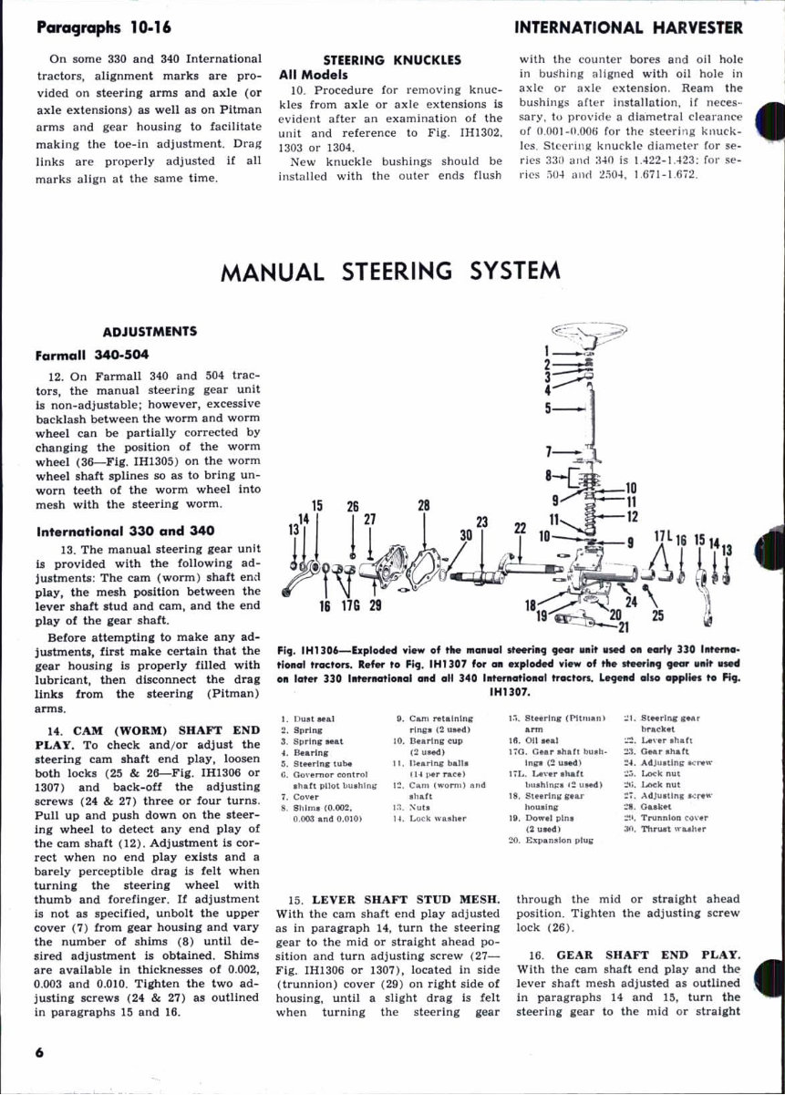
Paragraphs 10.16 On some 330 and 340 Int ernational tractors, alignmen t marks are pro- vided on s teering afms and axle (or axle extens ion s) as well as on Pitman arms and ge ar housing to facilitat e making the toe-in adju s tment. Drag links ar c prope rly adju st ed if all marks ali en at the same time. STEERING KNUC KLES All Mod e ls 10. P rocedure for removing knuc- kle, from axle or axle e xtensi ons is e vident af t er an exa mination of the unit and reference to Fi g. IH1302, 1303 or 1304 . New knuckle bushings should be in sta lled with the oU \l'r ends flu sh INTERNATIONAL HARVESTER w ith the coun ter bores and oil hole in bushing aligned with oil hol e In aslc or axil' e xtension . Ream the bush\nl!:S aftef insta llati on, if neces- sary, 10 provide a dlametrai clearance of n. OO J- u.OOG for t he st ecri ng klluck· [eli . Stel'L'illj( knuc kle diamctcl' (or se- ries :l:!O ann :141} [s 1.422 -1. 423: for se - ries .-)0 4 llnd 1."00 4, Ui71-1.672 . MANUAL STEERING SYSTEM ADJUSTMENTS Far mall 340·504 12. On Farmall 340 and M4 trac- t ors , the manual steerlna: gear unit is non-adjustable ; however, excess ive backlash between the worm and worm wheel can be partially correc ted by chana:ing the position of the worm wheel ( 36-Flg. IH1305 ) on the worm wheel s haft spli nes so as to bring un- worn teeth of the worm wheel Int o melh with th e s teerin, worm. Inter nat iona l 330 and 340 13. The manual steering gear unit is provided with the following ad- justments : The cam ( worm ) shaft end play, the mesh position between the lever shal t stud and cam, and the end play of the a:ear s hatt o Before attemptlna: to make any ad- justments, first make certain that the a:ear housing is properly filled with lubricant, then disconnect the drag links from the steerlna: (PUman) arms. 14. CAM (WORM) SH AFT END PLAY. To check and/ or adjust the I teerin g cam shaft end play. loosen both locks ( 25 & 26-Flg . IH1306 or 1307 ) and back-oU the adjustlna: sc rews (24 & 27) three or four turns. Pull up and push down on the steer- ing wheel to detect any end play of the cam shaf t (12) . Adjustment Is cor- reet when no end pl ay exists and a barely perceptible draa: is lelt when turnlna: the steering wheel with thumb and forefinger . If adjustment is not as specified. unbolt the upper cover (7) from gear housing and vary the number of s hims ( 8) until de- sired adjustment is obtained. Shlm.~ are available in thicknesses of 0.002, 0.003 and 0.010. Tla:hten the two ad- justin, sc r ews (2 4 & 27 ) as outlined in par agraphs 15 and 16. 6 FI, . IH1l06-- bpl odH 'tlew of t INt mOlllla[ ItHri., , eor 1I.1t liNd 0- ""y no [ trtfi"IHI. ri o-I tract ors. .. , .... '0 F it. [HI ) 07 for _ n plo6H 'ti_ 0' '" ........ 1119 .- IIfllt II...! 011 [ at" no III~n.otloIlOI OfId oil 340 [1I' eraati oll o[ ".,o n. L~ Ci llo o,p['" '0 ~,. [HU07. L l)!Jo l .... I •• Cam .... t.lnlnll . Spnnc r1n1:. (2 1It+d) 3. Sprlnc .. at ". n.ar1nl cup .. S .. rtnc (ZIIMd) ,. StouLn. l ilt.. H. 1I •• rt", baLI . Il . eO"emor ""nlroL (L~ ....... c. 1 • ~a!l pLlot l>1I.hlnll I~ . Cam Iwonn) ~nd 1. Co,·u .h.rt •• Shim. 10.007 . 1 ~. ;iu,. 0.0G.l an d 0.010) H. [..oc:k ... uh.r 15. LEVER SHAFT STUD MES H. With the cam shaft end play adj usted as in paraliilraph 14, turn the steerini gear to the mid or s traight ahead po- sition and turn adjustinJ sc rew (27- Fi g. IH1306 or 1307), located in side (trunnion) cover ( 29 ) on ri ght side of housing, until a slight drag is felt when turning the steering Iiilear 1.- •• StHdnc (NU"a,,1 ~I . SIH r lne ..... .~ ttrackfl. 18. on Hal .• lA,·o •• hah I~O. eM . aha! . bll.h_ Z-l. OMr ahall !n~(!IIMdI :~. AdJII.tln\: ......... 1 : 1.. IA"U .hall ~;;. I..oc:k nlll b".Mru:. ,: uMd) ::0;. Loek nlll ". Slunnlllr ... r ~; . Ad JII.llnc .., ....... ho .... lnI: ;:t . Oub! ". Do ... lllln. ::I'. Trunnion C O"., /211 _ 1 ;Ill . 11Irll.-t ...... h.r ~O. t:"'llan.lon Illll~ thr oua:h the mid or s traight ahea d posltlon . Ti ghten the ad jus tln , screw lock ( 26 ). 16. GEAR SHAFT END PLAY. With the cam s haft end play and the lever s haft mesh adjusted 31 outlined In paragrap hs 14 and 15 , turn the s teeri ng iear to the mid or st raight
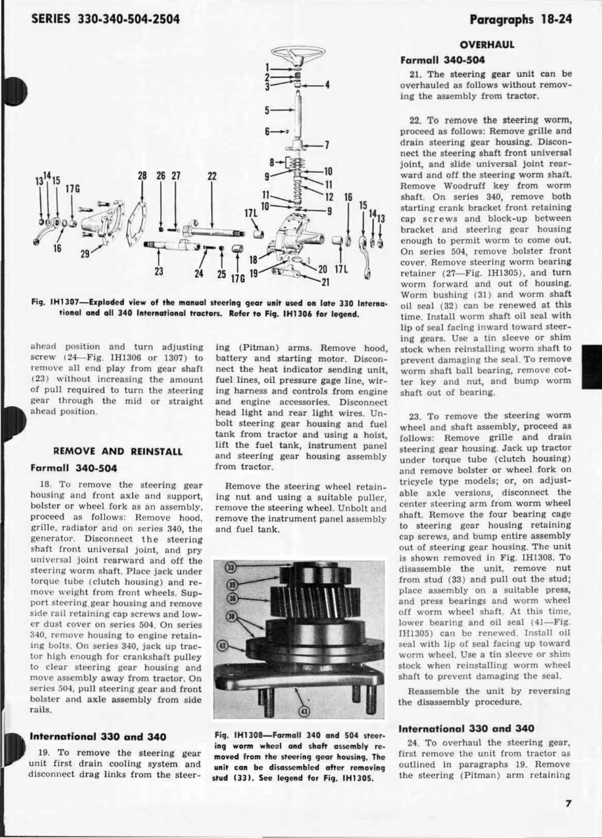
SERIES 330·340·504·2504 ~ ~ 1_ 2-- 3 --0.- 4 5- .,[J:o- - l 8- [" . II 28 261121 ~ 22 I: :f:\! 16 I( \ It Il lG Co .'. 10-.&.0- l iS ~o ~.; 0' .. 1l~ 4}- 9 l'I 16 29 -r<'-'-I Ti i IV"" " " 1 ~ 23 21 25 19 ~. 20 17L 116 21 Fill . IHl107-hplod ed . lew of the mOllwGI st eering ge ar IIlIlt ll sed 011 late ]]0 Interno. t iollol Gild all 340 1lI'. rllo,lollol tfoeton. Ref. r to Fig. IHl106 for I~elld. ahead positio n and turn adjusting screw 124- F ig. IHI 306 or 1307) to remove all end play from gea r shaft (23) wIthout increa sing the amount of pull required 10 tu rn the stee ring gear thr o ugh the mid or straight ahead posi tion . REMOVE AND REINSTALL Formall 340-504 18. To remove the stee r ing gear housing and fronl axle and suppo rt , bols t er or wheel l ork as an assembly, pr oceed as foll ows: Rem ove hood, grille, radiator a nd on ser ies 340, the generator. Di sconnect t he st eering s hart front un ive r sa l jo int, and pry univer sa l joint r ear ward and o ff th e st eering worm shaft. Place jac k under torque tube (clutch hou sing) and r e_ move weight from fro nt whee ls. Sup- port s teering. gear housing and r emove side .·ail retaining cap screws and low- er dust cover on series 504. On se ries 3-40 , remove housing to engine retain- IIlg boilS. On se rjes 3-10, jack up tr ac- tor high enough for crank~haft pulley 10 clear steering gear ho using and mO\'e assembly away fr om tractor . On series 50-4 . pull s teering gear and fr ont bo ls ter and ax le assemb ly from side rails. International 330 and 340 19. To re move the stee r ing gear u ni t fir st drain cooling sys tem and disconnect dr ag link s from t he st eer · ing ( Pitman ) arms . Re move hood, battery and starting motor . Discon_ nect th e heat Indicator sending unit, lu el Hnes, oil pressure gage li ne, wir- ing harness and con trols fro m engine and eng ine accessories. Disconncct h ead light and rear li g ht wires . Un- bo lt st eering gear housi ng and fuel ta nk from tractor and u sing a hoi st, lift the fuel tank , inst rument panel and s teer i ng gear hou sing assembly from tr a ct or. Remove the st eer i ng whee l r etain_ ing n ut a nd using a s uit ab le puller, r emove the stee r ing wheel. Unbolt and r emove the Instrument panel as sembly nnd fuel tank. Fig. IH1308-Fannall 340 alld 504 It" '· ill'J wann wh ee l alld shaft ouelllbir r eo IIIOyed f rolll the ,t_ ill 'J 'Jear hou sill'J . The ull it eOIl be di $Gsselnbled aft ef rema wl ll'J I tud Ill1. See le<Jetld for Fi'J . IHIl OS . Pan>9.aphs 18·24 OVERHAUL Farmall 340-504 21. The steering gear unit can be overhau l ed as follows witho ut r emov- ing th e assembly {rom trac tor . 22 . To remove the steering w orm, proceed as 10Uows: Remove grille and drain steering gea r housing. Discon- nec t the steeri ng shaft front un iversal joi nt, and slide un iversa l joint r ear- ward and oU the stee r ing w orm shait. Remove Woodruff key (rom worm shalt . On series 340, remove both s tarting crank bracket fr ont retain i ng ca p screws and bl ock -up between bracket and st eering gear housing enough to permit worm to come out. On series 504, remove . bolster fr on t cove r. Remove stcc ring wonn bea ri ng re taine r (27-Flg. IHI305 ), and turn worm f or ward and out of housing. Worm bushing (3 1) and worm sha.ft oil seal (32) can be renewed at this time. I nstall worm shaft oil seal with lip of sea l facing inward toward steer- Ing gears. Use a tin sleeve or shim stock when reinstalling worm s haft to pr event damaging the seal. To remove worm sha ft ball bearing, remove cot- ter key and nut, and bump worm .shaH out of bearing. 23 . To r emove the steering worm wheel and shaft assembly, proceed as loll ows: Remove g rill e and drain steering gear housing. Jack up tr ac tor un de r to rq ue tube (clutch housing ) and remove bolste r or wheel fork on tricycle t ype models; or, on adjust- able axle ver sions, disconnect the center st eering arm from worm wheel s haft . Remove the four bearing cage to st eering gear housing re tai n ing ca p scre ws. and bump en tir e assem bl y o ut of st eering gear housing. The unit Is sho wn removed in Fig. IHI30S. To disassemble the un it, remove n ut from st ud ( 33 ) and pull out the s tud: place assembly on a suitab le press, and press bearings and worm wheel off worm wheel shaft. At this time, lower bearing and oil seal ( 41 - Fig . IH1305) can be renewed . In stall oil sea l with lip of seal facing up toward worm wheel. Use a tin sleeve or shim st ock when reinstaUing worm wheel shult to prevent damaging the seal. Reassemble the unit by reversi ng the disassembly procedure. International 330 and 340 24. T o overhaul the steering gea r, first remove the unit from tractor as outlined in parag r aphs 19. Remove the s teering ( Pitman ) arm r etai n ing 7
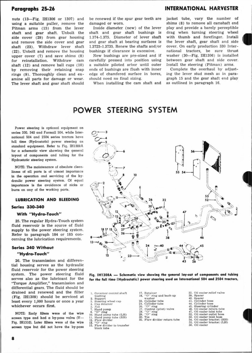
Paragraphs 25-26 nuts (I3--Flg, IHI306 or 1307 ) and using a suItable puller, remove the Pitman ann! (15) (rom the l eve r sha ft and iear shaft. Unbo lt the s ide cove r (29) from gear hous ing and remove th e side cover and gear shalt (23). Withdraw lever shaft ( 22 ). Unbolt and r emove the housing upper cover (7) and save shims (8) for r einstallation. With dr aw cam shalt (12) and remove ball cups (10) by f emov i n, lhelr r etaining snap rlnp (9 ), Th orou ghly clean and ex- amine all pa rts for damage or wear. The l eve r shaft and gear shaft should be r enew ed if the spur ,ea r t eet h are damaged or wo rn . In si de di a meter (new ) of the l ever s haft and gea r sha ft bushings Is 1.374-1.375. Di amete r of lever s haft and gear shaft at bearing su rfaces is 1.3725-1.3735. Renew the shafts and/ or bushings If clearance is excessive . New bushings are pre-sized and If care fully pressed in to position usln, a s uitabl e pil o ted ar bor until outer ends of bushings are flush with inner edge of ch amfered s urfa ce in bores, shou ld m_"Cd no final sizing. When Insta ll ing the cam sh aft an d INTERNATIONAL HARVESTER jac ket tube, vary the number of sh ims (8) to remove all camshaft e nd pl ay and provi de a barely perceptible drag when turning st eering wheel with thumb and f orefinger. Install the lever shait, gear shaft and si de cover. On ear ly production 330 Inter- nationa l tractors, be sure thrust washer (3G--F I I. IHI306) is insta lled between gear s haft and s ide cover . I nstall the s teering ( Pitman) arms . Complete the overhaul by adjust- ing the l ever stud mesh as in para - grap h 15 and the gear sh alt end play as outlined In paragraph 16. POWER STEERING SYSTEM Po .... r Itler lnq U opti ona l equip ment on Md. .. 330, 340 oDd Formoll S04. wb.1l. t ntll- notional ~ ond 2504 .. rie, IIOc:ton havo IIiU tim, (Hydra.lotlc) power 11 •• tiD; 05 . t(lDdord equipment . R,fer to ng. !H1308A lor (I ..::bematk: .,11'" Ihowinq Ib, glnlral layout 01 compon.nt. and t",bl.DCiiI lor Ih. KTCkoetaUe tI"riDq 'f8t.m. NotE.: Tb. malnt.nonc. 01 ab.o!",l. clean · l.l..c_ of all parta Ia of "'Imoet Imponan~. I.D the operation and M,vldnq 01 th. hy· d.ro:rullc: pow.r It",lnq Iy. tlm. Of eq1.Igl b:llportonce 18 th. ovoidonee 01 nicb g, bwa 011 any 01 the wodllnq pan.. lUBRICATION AND BLEEDING Series 330-340 With " Hydra.Touch " 25. The regula r Hydra-Touch sys tem fluid reservoi r is the s~urce of fluid s upply to the power st eer ln, sys t em . Refer to para ,ra ph 184 or 185 con - cernin, the lu brication requirements . Serle. 340 W ith out " Hydra-Touch " 26. The lraosm bl lon and dUieren- Ual hous ing se rves as the hydraulic fluid r eservoir for the powe r st ee r ing system. The powe r st eer ing fluid serves also as the lubri cant for the "Torque Amplifi er," tra nsmission and diHerential ,eon . The flu id shou ld be drained and rene wed and the filt er ( Fig. IHI309 ) .hould be serviced at least eve ry 1,000 ho urs or once a year whichever occurs flnt. NOTE: Eorly lUte... w.r. 01 Ih. wir' 1Cf •• n type! QDd had a by· pou val", (V- fir:. 1111310). Later flIt ......... r. 01 the .... ir. SCT"n t,.-poe btlt did not have the by·po .. a q . " .. -D Fi,. tHUOS ... _ Sclte!Ratlc .Iew d!owi., rile ~I lay .. llt of c_poHtlt's _d tub"', fOf the full ti_ (Hydrostatic: I pow., If"".,.ud _ l. fe,. at l_oJ 504 GH 2504 tTocton. I. Co,' .. "o, conl ....1 .hdl b".hlng 2. Support ~. SINnnr ... h.,..1 up t. Cap NI "lnor l. ;-':u, 1. Hand p"mP 8. "0" rlnr 10. Ii """ pump lube ( LH) I L H"nd pump tube (RU) 12. "'ow d,,·lda. IS. "0" rlng I~. Flo .. dIVIder 10 ' ... nol ". block t"be 17. Retalne. IS. "0" rln. &lid ... ck_up .... h• • U. CrUlld" ."be 21. Crllndt. l ube ~6. "0" nng ~1. COf'I l roI (pUo.) nl'" 28. "0" n". :w. "0" tIn. 30. T • • 32 .• '0'" d l,·\d ..... Iu.n l ube 3l. Oil cool ...... !lef .. alva 18. Spaoc. .0. S.,..,.. ~3. GrU"d •• h_ H. G,U"d.~_ .u. 81 Nrlnr qllltd •• -lfI. Oil cool ...... tum tube ~1. OIl_I • •• ola' t ube ~2. OIl coo ••• OIIUtt boN M. on cool .. In.n h.,.. M. 011 <>oolt. b""ka' (RU) ll. on cooler b.aeka. (Ul) ~. 01) ~""I.t
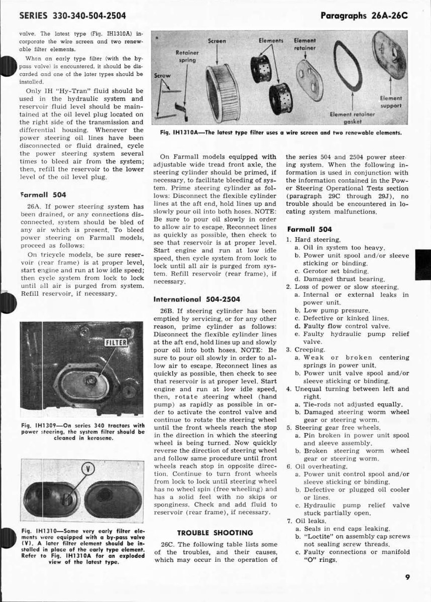
SERIES 330.340.504.2504 valve. The latest type ( fig. 1H1310A) in· corporate the wiIe screen and two renew- ab le lilter elements. Wh en on early type !iller ( with the by- pass valve) is encount ered. it s hould be dis- oorded and one 01 the later typo. should be in$wlled. Onl y IH " Hy-Tran " fluid shou ld be used in the h ydrau lic syste m and res erv o ir flu id leve l should be main- t ained 31 Ihe oil level plug located on Ihc right sid e of the transmission and differen tial housing. Wheneve r the po wer s teer ing oil lines have been disconllec t ed or fluid drained, cycle thc po wer steering system several Urn es \0 bleed air from the system; then, refill the reservoir to the lower l evel of the oil leve l plug. form all 504 26A. If po wer s teering system has been drained, or any connec tions d is~ conn ec ted , s. vs tem s hould be bled of any air which is present. To bleed po wer s teering on Farmall models, pr oceed as fo ll ows: On 'ri cycle mOdels, be sure reser- voir (rear frame) is at proper level, s tart e ngine and run:11 low idle speed; then cycle sys tem from lock to lock until 1111 air is purged from sys tem. Reflll r ese rvoir , if necessary. Fig . IH1109_0n series 140 traetars with power l. tccrino:! . the system filter shautd be cle aned in ke rose ne. Fio:! . IH1lt O-Some very early filter ele- me nt s .,e re e quipped with a by-pan volve (Y I. A latcr filter e lement should be In. staU ed in plac e of the e ar ly type ele ment. Refe r to Fig . IH1l10A for on ex pladed view of the lotelt type . • .e ta iner sp.h,,, ~ Paragraphs 26A·26C Elemen t suppor t Fig. IHUIOA-The lotelt type filtet uses a wire Kteen and twa renewable eleme nll . On F armall models equ ipped with adjus table wide tread fron t axle, the stee r ing cylinder s hould be p rimed , if necessary, to facilitate bleeding of sys- tem , Prime steering cylinder as fol- lows: Di sconnect the flexible cylinde r lines at the aft end, hold lines up a nd s low ly pour oil into both hoses , NOTE : Be sure to pour oil slowly in or der to all ow air to escape. Reconnect Jines as quickly as poss ible , then check to see that reservoir is at proper level, Start engine and run at low idle speed, t hen cycle system from l ock to l ock until aU air is purged from sys- tem . Refill res ervoir ( rear frame) , if necessary. In ter national 504-2504 26B. H steering cy l inder has been emptied by ser vicing. or lor any other reason , prime cylinder as follows: Di sconnect the flexib le cylinder lines at th e aft end, hold lines up and slo wly pour o il in to both hoses . NOTE : Be sure to pour o il slowly in orde r to al- low air to escape. Reconnect lines as qui ckly as possible, then c heck to see that r eservoir is at pr ope r le ve l. S t art engine and r un at l ow idle sp eed , then , ro t ate steering whee l ( ha nd IlUm p) as ra pidly as possible in or· der to ac t ivate the control valve and contin ue to r otate the st eer i ng wheel until the front wheels reach the stop in the direction in which the steer i ng wheel is being turned. Now quickly reve r se the dircction of steeri ng wheel and follow same procedure until front whcels reach stop in oppos ite direc- tion . Con tinuc to turn fr on t wheels from lock to lock until steering wh ee l has no wheel spin (free wheeling) and has a solid feel with no sk ips or sponginess, Check and add fluid to reservoir ( rcar fr ame), if necessary. TROUBLf SHOOTING 26C. The following table li sts some of the troubles, and their causes, which may occur in the operation of the serics 504 and 2504 power steer· ing system. W hen the foll ow ing in· f ormation is used in conjunction with the info r mation contained in the P ow- er Steering Operational Tests secti on ( paragraph 29C through 29J ), no tr ou ble should be encountered in lo- ca tin g system malfunctions, Farmall 504 1. Hard stee r ing. a 011 111 system too heavy , b. Power um! spool and / or sleev e ~ sticking or binding. c. Gerotor set bindin g d Damaged thru st bearing 2. Loss of power or slow st eering . a. Internal or exte r nal leaks in power unit. b, Low pump press ure , c. De fective or kinked lines . d, F aulty flow cont r ol valve. e. Faulty hydraulic pump relief valve . 3. Creeping . a. W eak or br oken cen te ri ng spri ngs in power un it . b. Power uni t va l ve s pool and / or sleeve s ticking or bind ing. 4. Unequal turning between lert and right. a. T ie- rods no t ad justed equally. b. Damaged steering worm wheel gea r or steering wo rm . S. Stee r ing gear free w hee ls. a, P in broken in power un it spool and sleeve assembly. b. Broken steer i ng w orm wheel gea r or steering worm . G. OB overhea ting. a. Po wer unit control spool and / or sl eeve s ti cki ng or binding. b. Defective or plugged oil coole r or lines. c. Hydraulic pump relief valve stuck partially open . 7. Oil leaks. a. Seal s in end caps leaking. b. "Loctite " on assembly cap screws not sealing screw threads. c, F aulty connections or man ifold " 0" ri ngs. 9
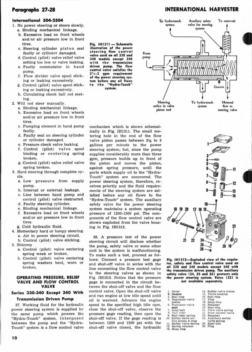
Panographs 27·28 International 5()4..2504 1. No power . teerin, or steers slowly. a. Blndln, mechanical link_Ie, b. Exceuive load on iront wheels and / or air pressure low In front tires, c. Steerin, cylinder pilton seal faulty or cyllnd<"r damaged. d, Control (pilot) valve relief valve setnn, too low or valve leaking . e. Faulty commutator In hand pump , t. Flow divide r va lve spool s tick- Ing or leaking excessively . ,. Control (pilot) va l ve spool . Uck. Ing or leaking exceuively . h. ClrculatJni check ball not seat- Ing. 2. Will not .teer manually , •. Blndln, mechanical linkage . b. Excessive l oad on front wheels and / Of air pressure low In front tires. c. Pumping elemen t In hand pump faulty , d. Faulty seal on . teerln, cylinder or cylinder damaged , e. Pressure check valve leaking, f. Control ( pilot ) valve spool bindln, or centerln, sprln, broken . ,. Control (pil ot) valve relief vBlve sprin, broken . 3. Hard s teerln, throu,h complete cy- cle. a. Low pre uure from supply pump . b. Internal or external leaka,e. c. Line between hand pump and control ( pilot) valve obatructed . d. Fauity stee rln , cylinder. e. Blndln, mechanical IInkale . t. Excessive load on front wheels and l or air pressure low In front tires . I. Cold hydraulic fluid . 4. Momentary hard or lumpy steerln,. a. Air in power steer lnl circuit . b. Control ( pilot) valve stickln,. ,. Shimmy a. Control ( pilot ) valve centerln, sprln, weak or broken . b. Control ( pilot ) valve centerln, sprin, washers bent, worn or broken. OPERATING PRESSURE. RlllEF VALVE AND FLOW CONTROL VALVE S.ri.s 330-340 Exc.pt 340 With Transmission Drl .... n Pump 27. WorkIn, fluid for the hydra uli c power steerln, Iystem Is supplied by the same pump which powers th e " Hydra-Touch" sy. t em. Interpose d between the pump Bnd the "Hydra- Touch" sy.tem Is a flow control valve '0 Fig. IHUlI _ Sche",atlc IIIl1lt rat lon of ... powor , toorl_9 flow co_tr.1 voivo 115e4 .. all 3]0 alld 340 ",odell olcept 340 wit. ,h. h'a_5III 1151_ IIIr lvet! pu"'p. T1Ie flow eOllh'a1 vO'lve l at isfJn th. :n 'l '] gp'" reqll\,..",,,, of thoe power 1teering "' .. te", before OilY 011 fiowl to tfrl . " HydrO'·Tolleh" Iyltltm. mechanism which Is shown Ichemat- ically In Fli. IH1311. The small me- terin, hole fn the end of the flow va l ve piston passes between 2", to 3 ,allons per minute to th e power steering system; but, since the pump supplies considerably more than three gpm, pressure build s up In front of the piston and moves the piston, a,alnst spring pressure, until the ports which s upply 011 to the ''Hydra- Touch" system are uncovered . The power s teerin, system, therefore, re - ceives priority and the fluid require- menta ot the steering s ystem are sat· isfied before any oil flows to th e "Hyd ra-Touch" system. The auxiliary safety valve for the power steering system maintains a system operaUn, preS5ure of 1200- 1500 psi. The com- ponents of the flow control valve are shown expl oded from the valve hous- In, In Fig. IH1312. 28. A pressure test of the power stee ring circuit will disclose whether the pumP. safety valve or lOme other unit In the system Is maltunctlonln,. To make such a test , proceed u fol- lows: Connect a pressure test pge and shut-oU valve in series with the line connecting the flow contro l valve to the steeri ng valves u shown In Fi g. IH1313. Notice that the pressure ,age Is connected in the circuit be~ tween the shut-oft valve and th e flow control valve. Open the shut-off va lve and run engine at low Id le speed unUi oil is warmed . Advance the enllne speed to the specified high Idle rpm , dose the shut-oU valve, oh5erve the pressure gage r eading, then open Ihe shu t-oU valve . It the ,a,e readln, 1 .1 between 1200 and 1500 psi with the shut-oU valve closed, the hydraulic INTERNATIONAL HARVESTER A~'" a1"y To racrvoir val~ lor ~tcrina .,..~ To hydn-toum .,.~ , ~ 3~ 4-- : ::; '-" '''1 a-- '2 11 a= :: FIg. IH1l12-bplodH .low.f tM ,...10. tor, ..... ,., olld flow eo.mol .01Ye .sed _ all ]]0 oM ]40 ."Is .. ce pt 340 witt! tile 'reI_lssl.a lllri ... ,..p . TM oulllory ..... ,., .04 •• U4 , 25 _d 2U PreltKti oaly ... powet IfeftIIl9 1YIf_. Val •• I n I I. aat ....oll oble M9Grot.ly. I. 00.,.,. •• Dubt 4. SM.111 .... ~. R..,.I.to. ".10', p lMOII •. It,,,,,'.t,, .... h·, - 1. tjt .. 1 ball _. nail 110\ •• t. 8aJ1114, •• p. ln, 10. ilal 'lJ .al". OTi· tL.,. -.; ... n .. ph., II . SatUy ... I .... ro .l n' 12 . Brorln, ... taln, . IS . anap rl .... 14 . Sateb' .a1, .. "laton I~. Val., howl,.. 18. l!e&1 11,.. lj . Pl\ll: I'. Bn .. rlnll It. R,tal", • :!O. Seal.tlll: ~, . ~,., .. "..av. '1'11" . ;:- .:. F10w ODRt ... 1 "..a ... ~. Retainer ~ •. A\lamary .. telJ "a1.,., 'J)11Ila 25. BtMl ball :It. PlUS
This IH International Harvester Farmall 504 tractor repair manual provides comprehensive instructions for maintaining and servicing your tractor, complete with diagrams and manufacturer specifications.
Navigation is made simple with convenient bookmarks and the ability to search by keyword. You can easily print out the entire manual or just the sections you'll be working on.
INSTANT - NO WAITING
LANGUAGE: English
FORMAT: PDF
COMPATIBLE: Win/Mac
BOOKMARKED - INDEXED - SEARCHABLE
The manual is fully bookmarked for easy navigation, allowing you to quickly identify the service repair procedures. It covers a wide range of topics including:
Belt Pulley
Brakes
Carburetor
Clutch
Cooling System
Diesel Fuel System
Differential
Direction Reverser
Electrical System
Engine
Final Drive
Front System
Governor (Non-Diesel)
Hydraulic System
Ignition
Main Drive Bevel Gears
Power Steering System
Power Takeoff
Service Data
Steering
Torque Amplifier
Transmission Overhaul
This manual is great for tune-ups, regular maintenance, or repairs, providing technical details and step-by-step instructions for all your needs. It is an easy-to-read PDF file that can be viewed, zoomed, and printed on any computer.
Why pay big bucks to have someone else print it for you? Print what you need when you need it.
We have thousands of manuals available, so feel free to email us about any others you might need.
Recently Viewed
5,521,897Happy Clients
2,594,462eManuals
1,120,453Trusted Sellers
15Years in Business
Price:
Actual Price:
IH International Harvester Farmall 504 Tractor Workshop Service Repair Manual -