International Harvester 684 Service & Repair Manual
What's Included?
Lifetime Access
Fast Download Speeds
Online & Offline Access
Access PDF Contents & Bookmarks
Full Search Facility
Print one or all pages of your manual
Due to a continuous program of research and development, some procedures, specifications and parts may be altered in a constant effort to improve our products. When changes and improvements are made in our products, periodic revisions may be made to this manual to keep it up-to-date. It is suggested that customers contact their dealer for information on the latest revision. NOTE: Some illustrations in this manual show equipment not currently available. The illustrations are used primarily to cover serviceability and may not always represent production equipment. A CAUTION! Some photograpbs in this manual may show shields or cover panels removed for purposes of clarity. NEVER OPERATE Unit without all shields and cover panels in place. Chassis 454, 464, 484, 57 4, 584, 67 4 684, 784, 884, 84 Hydro and 385 Tractors GS&-1416-B January, 1985 NOTE: Refer to the following service manual for service information not contained in this manual: GSS-1052C Testing and Servicing Electrical Equipment •
COMPLETE REVISION Chassis 454, 464, 484, 5'14, 584, 6'14 684, '184, 884, 84 Hydro and 385 Traetors Replace GS8-1416-1 w/Revision 3 with GS&-1416-B GSB-1416-B January 1985 Printed in United States of America
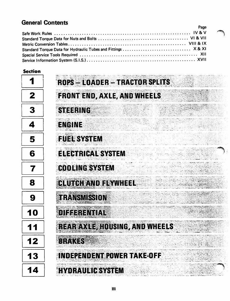
General Contents Page Safe Work Rules . . . . . . . . . . . . . . . . . . . . . . . . . . . . . . . . . . . . . . . . . . . . . . . . . . . . . . . . . . . . IV & V ~ Standard Torque Data for Nuts and Bolts ........................................ VI & VII Metric Conversion Tables. . . . . . . . . . . . . . . . . . . . . . . . . . . . . . . . . . . . . . . . . . . . . . . . . . . . VIII & I X Standard Torque Data for Hydraulic Tubes and Fittings . . . . . . . . . . . . . . . . . . . . . . . . . . . . . . X & XI Special Service Tools Required . . . . . . . . . . . . . . . . . . . . . . . . . . . . . . . . . . . . . . . . . . . . . . . . . . . . XII Service Information System (S.I.S.) ................................................ XVII Section I I D D D ~ L_j D D ~ L_j 00 . ' [0 ' . ~ ~ ~ L___2_j [ill ~ ~ ~ : : • ' • t ,. : ; • ~ ••• ' Ill
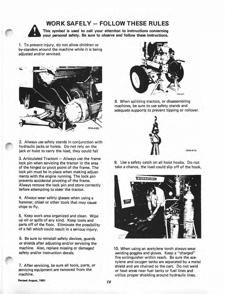
WORK SAFELY- FOLLOW THESE RULES A This symbol is used to call your attention to instructions concerning your personal safety. Be sure to observe and follow these instructions. 1. To prevent injury, do not allow children or by-standers around the machine while it is being adjusted and/or serviced. 2. Always use safety stands in conjunction with hydraulic jacks or hoists. Do not rely on the jack or hoist to carry the load, they could fail 3. Articulated Tractors- Always use the frame lock pin when servicing the tractor in the area of the hinged or pivot point of the frame. The lock pin must be in place when making adjust- ments with the engine running. The lock pin prevents accidental pivoting of the frame. Always remove the lock pin and store correctly before attempting to steer the tractor. 4. Always wear safety glasses when using a hammer, chisel or other tools that may cause chips to fly. 5. Keep work area organized and clean. Wipe up oil or spills of any kind. Keep tools and parts off of the floor. Eliminate the possibility of a fall which could result in a serious injury. 6. Be sure to reinstall safety devices, guards or shields after adjusting and/or servicing the machine. Also, replace missing or damaged safety and/or instruction decals. 7. After servicing, be sure all tools, parts, or servicing equipment are removed from the machine. Revised August, 1981 IV 8. When splitting tractors, or disassembling machines, be sure to use safety stands and adequate supports to prevent tipping or rollover. FESM-9718 9. Use a safety catch on all hoist hooks. Do not take a chance, the load could sl ip off of the hook . 10. When using an acetylene torch always wear welding goggles and gloves. Keep a "charged" fire extinguisher within reach . Be sure the ace- tylene and oxygen tanks are separated by a metal shield and are chained to the cart. Do not weld or heat areas near fuel tanks or fuel lines and ut ili ze proper s hi elding around hydraulic lines.
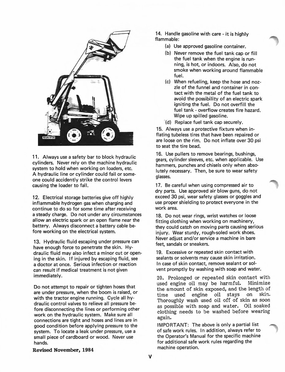
11. Always use a safety bar to block hydraulic cylinders. Never rely on the machine hydraulic system to hold when working on loaders, etc. A hydraulic line or cylinder could fail or some- one could accidently strike the control levers causing the loader to fall. 12. Electrical storage batteries give off highly inflammable hydrogen gas when charging and continue to do so for some time after receiving a steady charge. Do not under any circumstances allow an electric spark or an open flame near the battery. Always disconnect a battery cable be- fore working on the electrical system. 13. Hydraulic fluid escaping under pressure can have enough force to penetrate the skin. Hy- draulic fluid may also infect a minor cut or open- ing in the skin. If injured by escaping fluid, see a doctor at once. Serious infection or reaction can result if medical treatment is not given immediately. Do not attempt to repair or tighten hoses that are under pressure, when the boom is raised, or with the tractor engine running. Cycle all hy- draulic control valves to relieve all pressure be- fore disconnecting the lines or performing other work on the hydraulic system. Make sure all connections are tight and hoses and lines are in good condition before applying pressure to the system. To locate a leak under pressure, use a small piece of cardboard or wood. Never use hands. Revised November, 1984 v 14. Handle gasoline with care - it is highly flammable: (a) Use approved gasoline container. (b) Never remove the fuel tank cap or fill the fuel tank when the engine is run- ning, is hot, or indoors. Also, do not smoke when working around flammable fuel. (c) When refueling, keep the hose and noz- zle of the funnel and r.:ontainer in con- tact with the metal of the fuel tank to avoid the possibility of an electric spark igniting the fuel. Do not overfill the fuel tank- overflow creates fire hazard. Wipe up spilled gasoline. · (d) Replace fuel tank cap securely. 15 . Always use a protective fixture when in- flating tubeless tires that have been repaired or are loose on the rim. Do not inflate over 30 psi to seat the tire bead. 16. Use pullers to remove bearings, bushings, gears, cylinder sleeves, etc. when applicable. Use hammers, punches and chisels only when abso- lutely necessary. Then, be sure to wear safety glasses. 17. Be careful when using compressed air to dry parts. Use approved air blow guns, do not exceed 30 psi, wear safety glasses or goggles and use proper shielding to protect everyone in the work area. 18. Do not wear rings, wrist watches or loose fitting clothing when working on machinery, they could catch on moving parts causing serious injury. Wear sturdy, rough-soled work shoes. Never adjust and/or service a machine in bare feet, sandals or sneakers. 19. Excessive or repeated skin contact with sealants or solvents may cause skin irritation. In case of skin contact, remove sealant or sol- vent promptly by washing with soap and water. 20. Prolonged or repeated skin contact with used engine oil may be harmful. Minimize the amount of skin exposed, and the length of time used engine oil stays on skin. Thoroughly wash used oil off of skin as soon as possible with soap and water. Oil soaked clothing needs to be washed before wearing again. IMPORTANT: The above is only a partial list of safe work rules. In addition, always refer to the Operator's Manual for the specific machine for additional safe work rules regarding the machine operation.
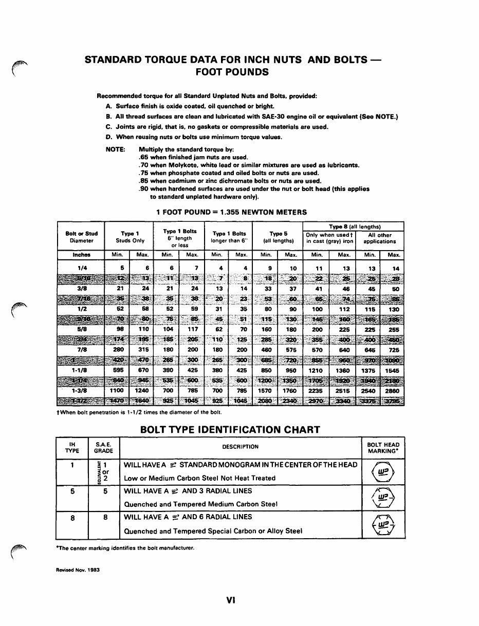
STANDARD TORQUE DATA FOR INCH NUTS AND BOLTS- FOOT POUNDS Recommended torque for all Standard Unplated Nuts and Bolts. provided: A. Surface finish is oxide coated. oil quenched or bright. B. All thread surfaces are clean and lubricated with SAE·30 engine oil or equivalent (See NOTE.) C. Joints are rigid. that is. no gaskets or compressible materials are used. D. When reusing nuts or bolts use minimum torque values. NOTE: Multiply the standard torque by: .65 when finished jam nuts are used . . 70 when Molykote. white lead or similar mixtures are used as lubricants . . 75 when phosphate coated and oiled bolts or nuts are used . . 85 when cadmium or zinc dichromate bolts or nuts are used . . 90 when hardened surfaces are used under the nut or bolt head (this applies to standard unplated hardware only). 1 FOOT POUND= 1.355 NEWTON METERS Bolt or Stud Diameter Type 1 Studs Only Type 1 Bolts longer than 6" t When bolt penetration is 1·1/2 times the diameter of the bolt. BOLT TYPE IDENTIFICATION CHART IH S.A.E. DESCRIPTION BOLT HEAD TYPE GRADE MARKING• 1 ! 1 WILLHAVEA ~ STANDARDMONOGRAMINTHECENTEROFTHEHEAD @ ~or Low or Medium Carbon Steel Not Heat Treated ~2 5 5 WILL HAVE A !!!! AND 3 RADIAL LINES @ Quenched and Tempered Medium Carbon Steel 8 8 WILL HAVE A ~AND 6 RADIAL LINES ® Quenched and Tempered Special Carbon or Alloy Steel •The center marking identifies the bolt manufacturer. Revised Nov. 1983 VI
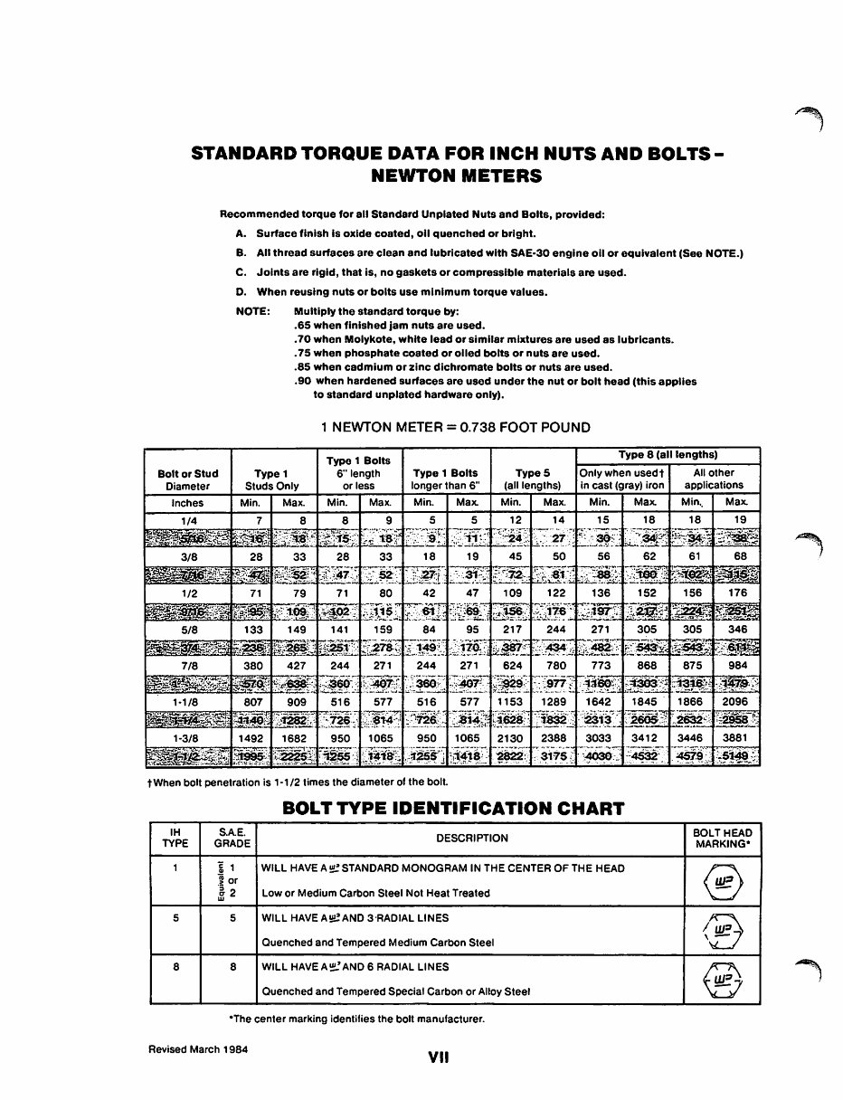
STANDARD TORQUE DATA FOR INCH NUTS AND BOLTS- NEWTON METERS Bolt or Stud Diameter Recommended torque for all Standard Unplated Nuts and Bolts, provided: A. Surface finish Is oxide coated, oil quenched or bright. B. All thread surfaces are clean and lubricated with SAE·30 engine oil or equivalent (See NOTE.) C. Joints are rigid, that is, no gaskets or compressible materials are used. D. When reusing nuts or bolts use minimum torque values. NOTE: Multiply the standard torque by: .65 when finished jam nuts are used • • 70 when Molykote, white lead or similar mixtures are used as lubricants . . 75 when phosphate coated or oiled bolts or nuts are used • . 85 when cadmium or zinc dichromate bolts or nuts are used • • 90 when hardened surfaces are used under the nut or bolt head (this applies to standard unplated hardware only). 1 NEWTON METER= 0.738 FOOT POUND Type 8 (all lengths) Type 1 Studs Only Type 1 Bolts 6"1ength or less Type 1 Bolts longer than 6" TypeS (all lengths) Only when used t All other in cast (gray) iron applications Inches Min. Max. Min. Max. Min. Max. Min. Max. Min. Max. Min .. Max. 1/4 7 8 8 9 5 5 12 14 15 18 18 19 ~~~~~~ ~~Jii~>~~~!5 ~~f~;-~·~tZF:~Ti :~J:i~~lef1~l i-~-:~~·:r._:nt~L~£; ~-:~;1~~~ ~~ ~--, 3/8 28 33 28 33 18 19 45 50 56 62 61 68 1~ 1 ~ ~~~~~~r;~~i.~J=~=:t:~~ =~~12~f~;1h~~t EL~J :.z~it~r~t~~~ ~~:, 1/2 71 79 71 80 42 47 109 122 136 152 156 176 ~~- ~211~ ri5~ 1;:2§!~~~ Gii~I7:S~lf. §fj~£ ~~-; E~1r~:~l~~~1~ -~~~ ~ 5/8 133 149 141 159 84 95 217 244 271 305 305 346 ~~~r , -;~'m~:t:~ ~;:~~ t~~sSt; ~~~f2 ~~~}1 ;k:l~~iC ::1;1"!~} ~~7_ ~f::~:~j; ~¥!2~~ ~t:~-; ~~ ~S~ 7/8 380 427 244 271 244 271 624 780 773 868 875 984 --~;~: ~~ ~H~it";!~~~:~ h~~~- ):¥0~~ ~L~??:: ;~~l ~:.:~I~!!~~~~P~±;~~1 :~~:_;, :~:1WI"·X:: 1·1/8 807 909 516 577 516 577 1153 1289 1642 1845 . 1866 2096 ~ll~~~~ •~ j-~·~II 2~§·; ;·;D!i~ ~;~~l;; ~:;!~~rt r~~~; 1~1 ~;~~:~~~@~~"~In~ 1-3/8 1492 1682 950 1065 950 1065 2130 2388 3033 3412 3446 3881 ~~~; ~~ ::~~ ~~j J~f~~ ;::j~~~;J :Gtiii~L -~~#·:: 7.~¥fs~( :~~~~ _:~~-- :~~!~·:,:~ \~~}, tWhen bolt penetration is 1-1/2 times the diameter of the bolt. BOLT TYPE IDENTIFICATION CHART IH S.A.E. DESCRIPTION BOLT HEAD TYPE GRADE MARKING* 1 i 1 WILL HAVE A~ STANDARD MONOGRAM IN THE CENTER OF THE HEAD @ ~ or -~ 2 Low or Medium Carbon Steel Not Heat Treated w 5 5 WILL HAVE A !I!! AND 3-RADIAL LINES 13 Quenched and Tempered Medium Carbon Steel ,- 8 8 WILL HAVE A~ AND 6 RADIAL LINES ® Quenched and Tempered Special Carbon or Alloy Steel *The center marking identifies the bolt manufacturer. Revised March 1984 VII
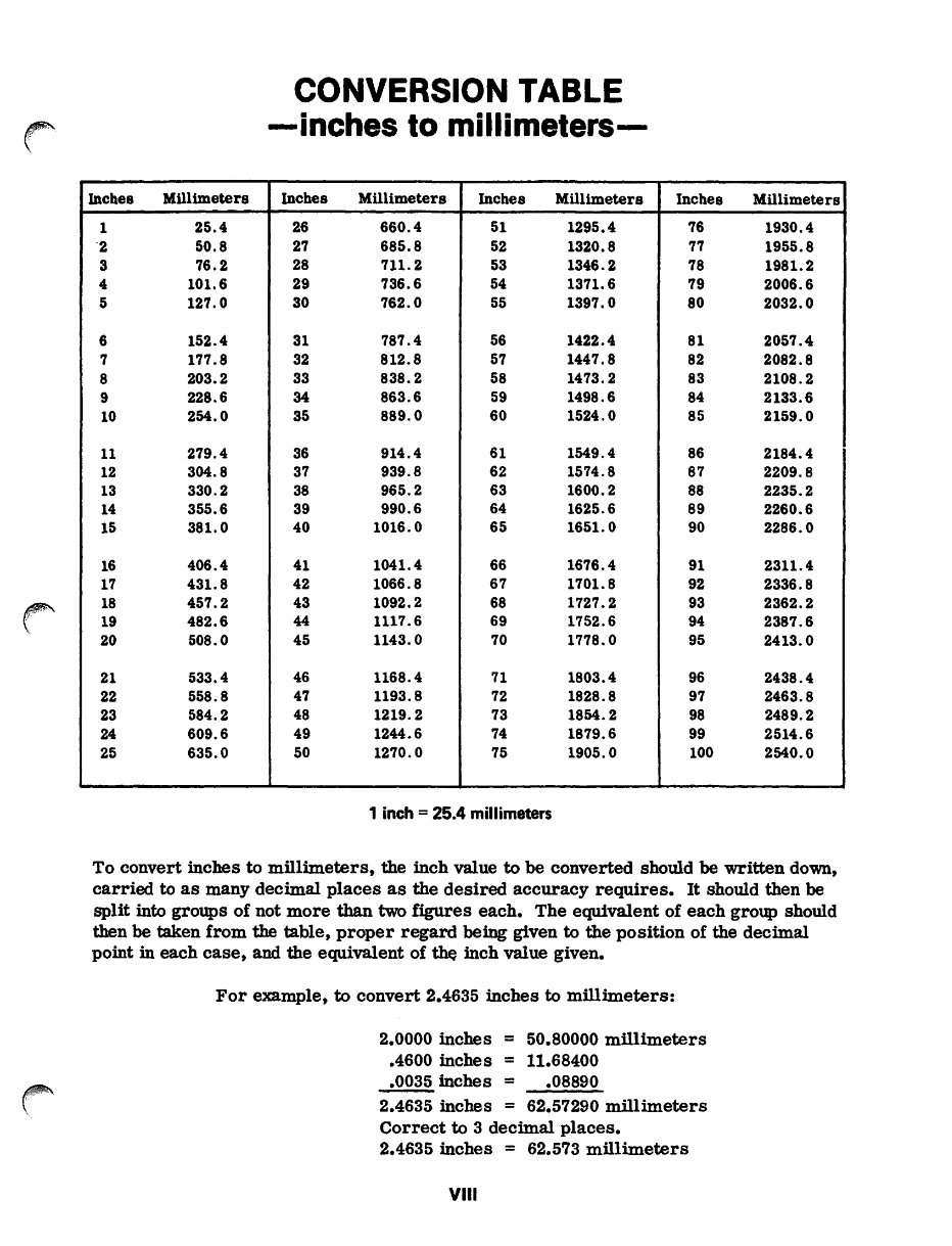
Inches Millimeters 1 25.4 .2 50.8 3 76.2 4 101.6 5 127.0 6 152.4 7 177.8 8 203.2 9 228.6 10 254.0 11 279.4 12 304.8 13 330.2 14 355.6 15 381.0 16 406.4 17 431.8 18 457.2 19 482.6 20 508.0 21 533.4 22 558.8 23 584.2 24 609.6 25 635.0 CONVERSION TABLE -inches to millimeters- Inches Millimeters Inches Millimeters 26 660.4 51 1295.4 27 685.8 52 1320.8 28 711.2 53 1346.2 29 736.6 54 1371.6 30 762.0 55 1397.0 31 787.4 56 1422.4 32 812.8 57 1447.8 33 838.2 58 1473.2 34 863.6 59 1498.6 35 889.0 60 1524.0 36 914.4 61 1549.4 37 939.8 62 1574.8 38 965.2 63 1600.2 39 990.6 64 1625.6 40 1016.0 65 1651.0 41 1041.4 66 1676.4 42 1066.8 67 1701.8 43 1092.2 68 1727.2 44 1117.6 69 1752.6 45 1143.0 70 1778.0 46 1168.4 71 1803.4 47 1193.8 72 1828.8 48 1219.2 73 1854.2 49 1244.6 74 1879.6 50 1270.0 75 1905.0 1 inch = 25.4 millimeters Inches Millimeters 76 1930.4 77 1955.8 78 1981.2 79 2006.6 80 2032.0 81 2057.4 82 2082.8 83 2108.2 84 2133.6 85 2159.0 86 2184.4 87 2209.8 88 2235.2 89 2260.6 90 2286.0 91 2311.4 92 2336.8 93 2362.2 94 2387.6 95 2413.0 96 2438.4 97 2463.8 98 2489.2 99 2514.6 100 2540.0 To convert inches to millimeters, the inch value to be converted should be written down, carried to as many decimal places as the desired accuracy requires. It should then be split into groups of not more than two figures each. The equivalent of each group should then be taken from the table, proper regard being given to the position of the decimal point in each case, and the equivalent of the inch value given. For example, to convert 2.4635 inches to millimeters: 2.0000 inches = .4600 inches = .0035 inches = 50.80000 millimeters 11.68400 .08890 2.4635 inches = 62.57290 millimeters Correct to 3 decimal places. 2.4635 inches = 62.573 millimeters VIII
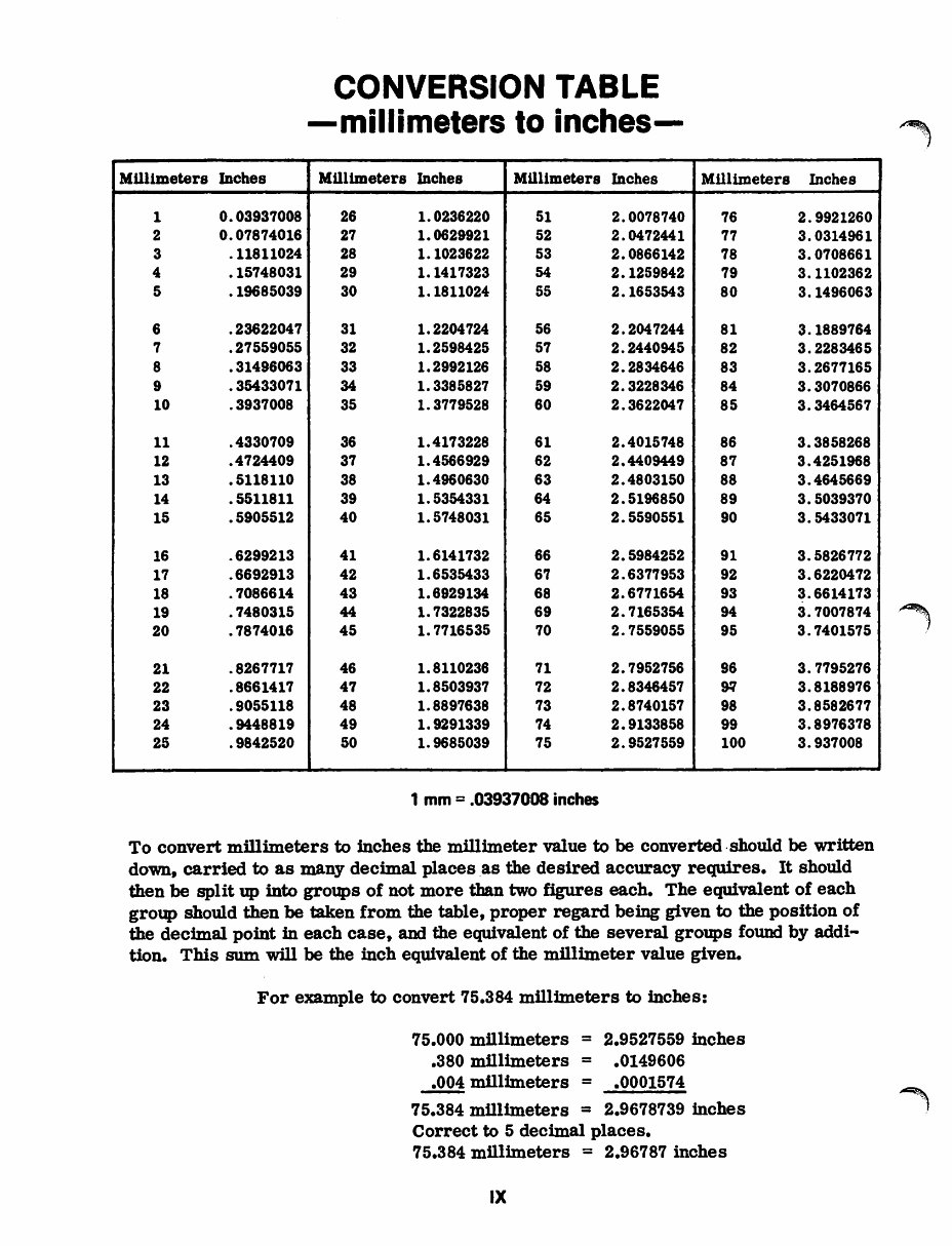
Millimeters Inches 1 0.03937008 2 0.07874016 3 .11811024 4 .15748031 5 .19685039 6 .23622047 7 .27559055 8 .31496063 9 .35433071 10 .3937008 11 .4330709 12 .4724409 13 .5118110 14 .5511811 15 .5905512 16 .6299213 17 .6692913 18 . 7086614 19 .7480315 20 .7874016 21 .8267717 22 .8661417 23 .9055118 24 .9448819 25 .9842520 CONVERSION TABLE -millimeters to inches- Millimeters Inches Millimeters Inches 26 1.0236220 51 2.0078740 27 1.0629921 52 2. 0472441 28 1.1023622 53 2. 0866142 29 1.1417323 54 2.1259842 30 1.1811024 55 2.1653543 31 1.2204724 56 2.2047244 32 1.2598425 57 2.2440945 33 1.2992126 58 2.2834646 34 1. 3385827 59 2.3228346 35 1.3779528 60 2.3622047 36 1.4173228 61 2.4015748 37 1.4566929 62 2.4409449 38 1.4960630 63 2.4803150 39 1.5354331 64 2.5196850 40 1.5748031 65 2.5590551 41 1.6141732 66 2.5984252 42 1.6535433 67 2.6377953 43 1.6929134 68 2.6771654 44 1.7322835 69 2.7165354 45 1. 7716535 70 2.7559055 46 1.8110236 71 2.7952756 47 1.8503937 72 2.8346457 48 1.8897638 73 2.8740157 49 1.9291339 74 2.9133858 50 1.9685039 75 2.9527559 1 mm = .03937008 inches Millimeters Inches 76 2.9921260 77 3. 0314961 78 3.0708661 79 3.1102362 80 3.1496063 81 3.1889764 82 3.2283465 83 3.2677165 84 3.3070866 85 3.3464567 86 3.3858268 87 3.4251968 88 3.4645669 89 3.5039370 90 3.5433071 91 3.5826772 92 3.6220472 93 3.6614173 94 3.7007874 95 3.7401575 96 3.7795276 9.!1 3.8188976 98 3.8582677 99 3.8976378 100 3.937008 To convert millimeters to inches the millimeter value to be converted.should be written down, carried to as many decimal places as the desired accuracy requires. It should then be split up into groups of not more tban two figures each. The equivalent of each group should then be taken from the table, proper regard being given to the position of the decimal point in each case, and the equivalent of the several groups found by addi- tion. This sum will be the inch equivalent of the millimeter value given. For example to convert 75.384 millimeters to inches: 75.000 millimeters = .380 mlllimeters = .004 mfilimeters = 2.9527559 inches .0149606 .0001574 75.384 millimeters = 2.9678739 inches Correct to 5 decimal places. 75.384 millimeters = 2.96787 inches IX
IH International Harvester 684 Tractor Factory Service Repair Manual is a comprehensive guide covering the maintenance and repair of the IH International Harvester 684 Tractor. It is a genuine repair service factory manual, providing in-depth insights into maintaining and repairing the tractor.
Useful for both professional mechanics and DIY enthusiasts, this manual covers various aspects including the engine, lubrication system, cooling system, fuel system, disassembly and servicing, clutch, transmission, brakes, steering, hydraulic system, electrical system, routine maintenance, advanced troubleshooting, and more.
The manual contains detailed illustrations, diagrams, and specifications to assist in repair procedures, along with an advanced troubleshooting guide for problem diagnosis and correction. It is available in English and can be printed without any restrictions. The file format is PDF, and it is compatible with all PC-based Windows operating systems and Mac.
This manual is a valuable resource for anyone looking to repair, maintain, rebuild, refurbish, or restore their IH International Harvester 684 Tractor. It provides detailed step-by-step instructions, photos, and diagrams, allowing users to easily navigate through service, maintenance, repairs, and tuning.
With this manual, users can save on shop labor costs and have the convenience of accessing and printing specific pages as needed. The manual also includes detailed substeps, notes, cautions, warnings, numbered instructions, and a table of contents for easy navigation.
Additionally, it offers guidance on diagnosing and repairing electrical system problems, combining troubleshooting and electrical service procedures with detailed wiring diagrams for ease of use.
Whether for professional technicians or DIY enthusiasts, this IH International Harvester 684 Tractor Factory Service Repair Manual provides comprehensive and indispensable information for maintaining and repairing the tractor.
Recently Viewed
5,521,897Happy Clients
2,594,462eManuals
1,120,453Trusted Sellers
15Years in Business
Price:
Actual Price:
International Harvester 684 Service & Repair Manual