

IH International Harvester 674 Repair Service Manual
What's Included?
Fast Download Speeds
Online & Offline Access
Access PDF Contents & Bookmarks
Full Search Facility
Print one or all pages of your manual
INTERNATIONAL
HARVESTER
Models H454 H464 m484 W574 H 584 H674
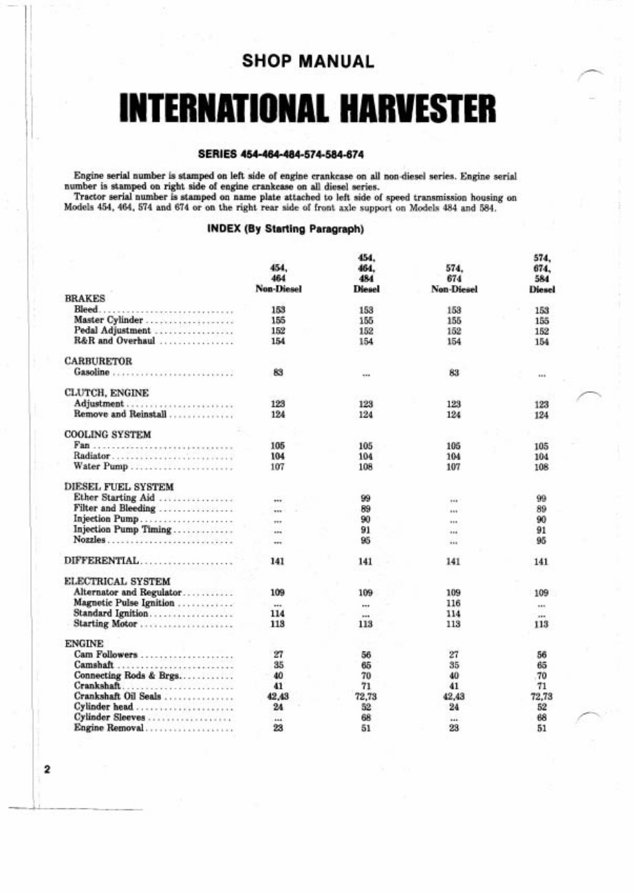
SHOP MANUAL
Engine serial number is stamped on left side of engine crankcase on all nondiesel series. Engine serial
number is stamped on right side of engine crankcase on all diesel series.
Tractor serial number is stamped on name plate attached to left side of speed transmission housing on
Models 454, 464, 574 and 674 or on the right rear side of front axle support on Models 484 and 584.
INDEX (By Starting Paragraph)
454,
464, 574,
484 674
Diesel Non-Diesel
574,
674,
584
Diesel
454,
464
Non-Diesel
BRAKES
Bleed. ............................ 153
Master Cylinder ................... 155
Pedal Adjustment ................. 152
R&R and Overhaul ................ 154
CARBURETOR
Gasoline ...............
CLUTCH, ENGINE
Adjustment ....................... 123 123 123
Remove and Reinstall. ............. 124 124 124
COOLING SYSTEM
Fan ..............................
Radiator ..........................
Water Pump ......................
DIESEL FUEL SYSTEM
Ether Starting Aid ................ ... 99 ...
Filter and Bleeding ................ ... 89 ...
Injection Pump. ................... ... 90 ...
Injection Pump Timing. ............ ... 91 ...
Nozzles ........................... ... 95 ...
DIFFERENTIAL ....................
ELECTRICAL SYSTEM
Alternator and Regulator. ..........
Magnetic Pulse Ignition ............
Standard Ignition. .................
Starting Motor ....................
ENGINE
Cam Followers ....................
......................... Camshaft
Connecting Rods & Brgs.. ..........
Crankshaft ........................
Crankshaft Oil Seals ...............
Cylinder head .....................
Cylinder Sleeves ..................
Engine Removal. ..................
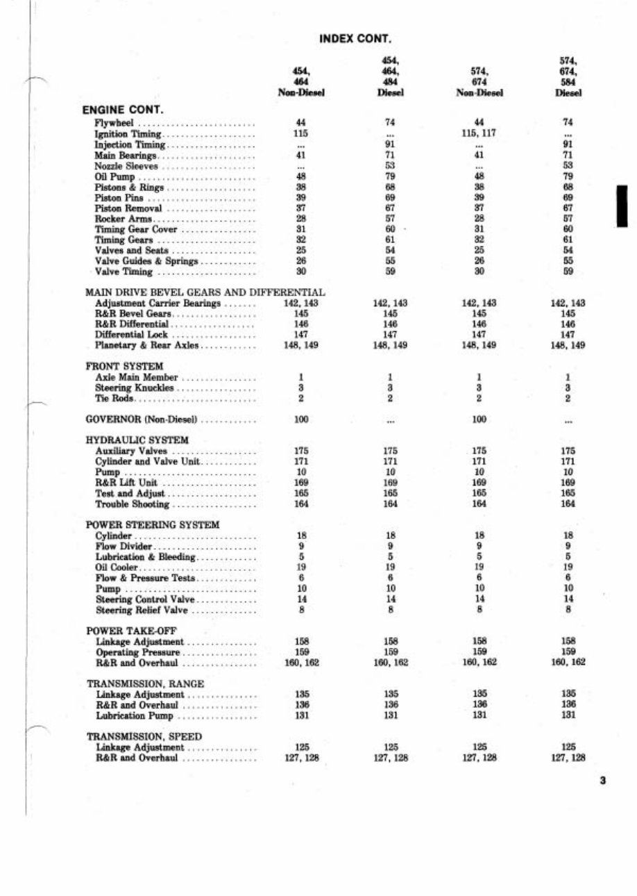
INDEX CONT .
454.
454. 464.
464 484
Non-Diesel Diesel
574.
674.
584
Diesel
574.
674
Non-Diesel
ENGINE CONT .
Flywheel .........................
Ignition Timing ....................
Injection Timing ...................
Main Bearings .....................
Nozzle Sleeves ....................
......................... Oil Pump
................... Pistons & Rings
Piston Pins .......................
................... Piston Removal
Rocker Arms ......................
................ Timing Gear Cover
Timing Gears .....................
Valves and Seats ..................
Valve Guides & Springs ............
Valve Timing .....................
MAIN DRIVE BEVEL GEARS AND DIFFERENTIAL
Adjustment Carrier Bearings ....... 142.143
R&R Bevel Gears .................. 145
R&R Differential .................. 146
Differential Lock .................. 147
Planetary & Rear Axles ............ 148. 149
FRONT SYSTEM
Axle Main Member ................ 1
Steering Knuckles ................. 3
Tie Rods .......................... 2
GOVERNOR (Non-Diesel) ............ 100
HYDRAULIC SYSTEM
.................. Auxiliary Valves
Cylinder and Valve Unit ............
Pump ............................
R&R Lift Unit ....................
Test and Adjust ...................
Trouble Shooting ..................
POWER STEERING SYSTEM
Cylinder ..........................
Flow Divider ......................
............. Lubrication & Bleeding
......................... Oil Cooler
Flow & Pressure Tests .............
Pump ............................
............. Steering Control Valve
.............. Steering Relief Valve
POWER TAKE-OFF
............... Linkage Adjustment 158
................ Operating Pressure 159
R&R and Overhaul ................ 160. 162
TRANSMISSION. RANGE
Linkage Adjustment ............... 135
R&R and Overhaul ................ 136
Lubrication Pump ................. 131
TRANSMISSION. SPEED
Linkage Adjustment ............... 125
R&R and Overhaul ................ 127. 128
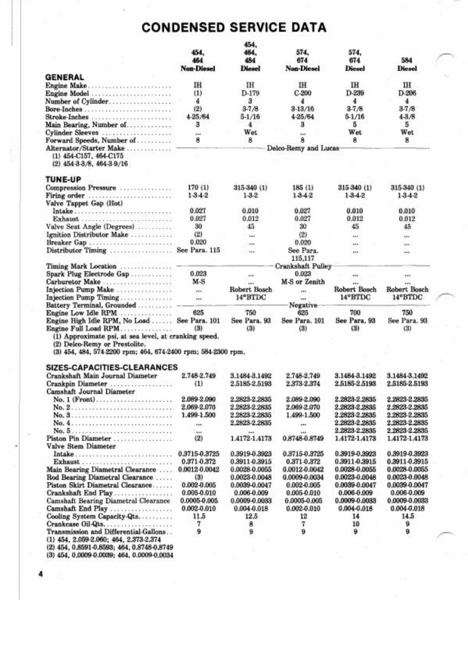
CONDENSED SERVICE DATA
GENERAL
Engine Make. .......................
Engine Model .......................
................. Number of Cylinder.
Bore-Inches .........................
Stroke-Inches .......................
Main Bearing. Number of. ............
.................... Cylinder Sleeves
Forward Speeds, Number of. .........
............. Alternator/Starter Make
(1) 454-C157, 4644175
(2) 45433/8, 4643-9/16
454,
464
Non-Diesel
454,
464,
484
Diesel
IH
D-179
3
3-7/8
5-1/16
4
Wet
8
574,
674
Non-Diesel
IH
C-200
4
3-13/16
4-25/64
3
...
8
Delco-Remy and Lucas
574,
674
Diesel
IH
D-239
4
3-7/8
5-1/16
5
Wet
8
TUNE-UP
Compression Pressure ............... 170 (1) 315340 (1) 185 (1) 315340 (1)
Firing order ........................ 134-2 13-2 13-4-2 13-4-2
Valve Tappet Gap (Hot)
Intake ............................ 0.027 0.010 0.027 0.010
Exhaust ..................... 0.027 0.012 0.027 0.012
Valve Seat Angle (Degrees) ....... 30 45 30 45
............ ... Ignition Distributor Make (2) (2) ...
........................ Breaker Gap 0.020 ... 0.020 ...
Distributor Timing .................. See Para. 115 ... See Para. ...
115,117
Timing Mark Location ............... Crankshaft Pulley
Spark Plug Electrode Gap. ........... 0.023 ... 0.023 ...
Carburetor Make .................... M-S ... M-S or Zenith ...
Injection Pump Make ................ ... Robert Bosch ... Robert Bosch
Injection Pump Timing. .............. ... 14OBTDC ... 14OBTDC
Battery Terminal, Grounded .......... Negative
Engine Low Idle RPM ............... 625 750 625 700
Engine High Idle RPM, No Load ...... See Para. 101 See Para. 93 See Para. 101 See Para. 93
Engine Full Load RPM. .............. (3) (3) (3) (3)
(1) Approximate psi, at sea level, at cranking speed.
(2) Delco-Remy or Prestolite.
(3) 454,484, 574-2200 rpm; 464.674-2400 rpm; 584-2300 rpm.
SIZES-CAPACITIES-CLEARANCES
Crankshaft Main Journal Diameter 2.748-2.749
.................. Crankpin Diameter (1)
Camshaft Journal Diameter
No. 1 (Front) ...................... 2.089-2.090
NO. 2 ............................. 2.069-2.070
NO. 3 ............................. 1.499-1.500
No.4 ............................. ...
No.5 ............................. ...
Piston Pin Diameter ................. (2)
Valve Stem Diameter
Intake ............................ 0.37154.3725
Exhaust .......................... 0.3714.372
Main Bearing Diametral Clearance .... 0.00124.0042
Rod Bearing Diametral Clearance ..... (3)
Piston Skirt Diametral Clearance. ..... 0.0024.005
Crankshaft End Play. ................ 0.0054.010
Camshaft Bearing Diametral Clearance 0.00054.005
Camshaft End Play .................. 0.0024.010
Cooling System Capacity-Qts. ......... 11.5
Crankcase Oil-Qts. ................... 7
Transmission and Differential-Gallons . . 9
(1) 454, 2.059-2.060; 464, 2.373-2.374
(2) 454,0.8591-0.8593; 464,0.87484.8749
(3) 454, 0.00094.0039; 464, 0.00094.0034
584
P
Diesel
IH
D-206
4
3-7/8
43/8
5
Wet
8
...
Robert Bosch
14OBTDC f-'
750
See Para. 93
(3)
Paragraphs 1-3
pull arm from steering knuckle. Re-
Ro SYSTEM move the Woodruff key and lower the
AXLE TYPE
steering knuckle assembly from axle
extension. Remove thrust bearing (4)
and felt washer (7). Hub and wheel
bearings can now be removed if neces-
FRONT SYSTEM AXLE TYPE sarv.
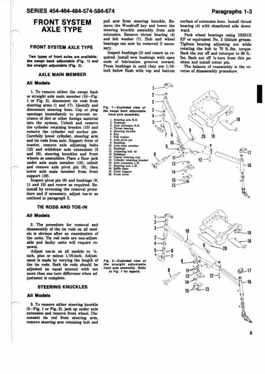
Inspect bushings (2) and renew as re-
TWOtypes of front axles are available;
quired. Install new bushings with open
the swept back adjustable (Fig. 1) and ends of lubrication grooves inward.
the straight adjustable (Fig. 2). Press bushings in until they are 1/16-
AXLE MAIN MEMBER
inch below flush with top and bottom
surface of extension bore. Install thrust
bearing (4) with chamfered side down-
ward.
Pack wheel bearings using IH251H
EP or equivalent No. 2 lithium grease.
Tighten bearing adjusting nut while
rotating the hub to 70 ft.-lbs. torque.
Back the nut off and retorque to 50 ft.-
lbs. Back nut off %-turn from this po-
sition and install cotter pin.
The balance of reassembly is the re-
verse of disassembly procedure.
All Models
*
1 -
1. To remove either the swept back
or straight axle main member (10-Fig.
1 or Fig. 2), disconnect tie rods from
steering arms (1 and 17). Identify and
Fig. view of
disconnect steering lines- Cap or plug
the swept back adjustable
openings immediately to prevent en- front axle assembly.
trance of dirt or other foreign material 1. sbring RH.
I
2. Bushings
into the system. Unbolt and remove
3. Axle extension RH.
the cylinder retaining bracket (15) and 4. nrust bearing
5. Steering knuckle
remove the cylinder rod anchor pin.
s. Key
aref fully lower cylinder, steering arm 7. Felt washer
and tie rods from axle. Support front of
: kx$g'," pin
tractor, remove axle adjusting bolts lo. Axle main member
(12) and withdraw axle extensions (3
:;: exg bolt ,*,
and 16), steering knuckles and front 13. Bushings
wheels as assemblies. Place a floor jaek
::: ~~~,"~~,g~rBeket
under axle main member (10). unbolt 16. Axle extension L.H.
and remove axle pivot pin (8), then
::: ~ ~ ~ p " l a ~ L.H.
lower axle main member from front
g: gtgrt
support (19).
Inspect pivot pin (8) and bushings (9,
11 and 13) and renew as required. Re-
install by reversing the removal proce-
dure and if necessary, adjust toe-in as
outlined in paragraph 2.
TIE RODS AND TOE-IN
All Models
2. The procedure for removal and
disassembly of the tie rods on all mod-
els is obvious after an examination of
the units. Tie rod ends are non-adjust-
able and faulty units will require re-
newal.
Adjust toe-in on all models to '14-
inch, plus or minus l/l6-inch. Adjust-
ment is made by varying the length of Fig. 2-Exploded view of
the tie rods. Both tie rods should be the straight adjustable
adjusted an equal amount with not
front ax" assembly. Refer
more than one turn difference when ad-
to Fig. 1 for legend.
justment is complete.
STEERING KNUCKLES
All Models
Q
3. To remove either steering knuckle
(6-Fig. 1 or Fig. 21, jaek up under axle
extension and remove front wheel. Dis-
connect tie rod from steering arm,
remove steering arm retaining bolt and
Paragraphs 4-5
HYDROSTATIC
STEERING
SYSTEM
NOTE: The malntenance of absolute
cleanliness of all parts Is of utmost im-
portance in the operation and servicing
of the hydrostatic steering system. Of
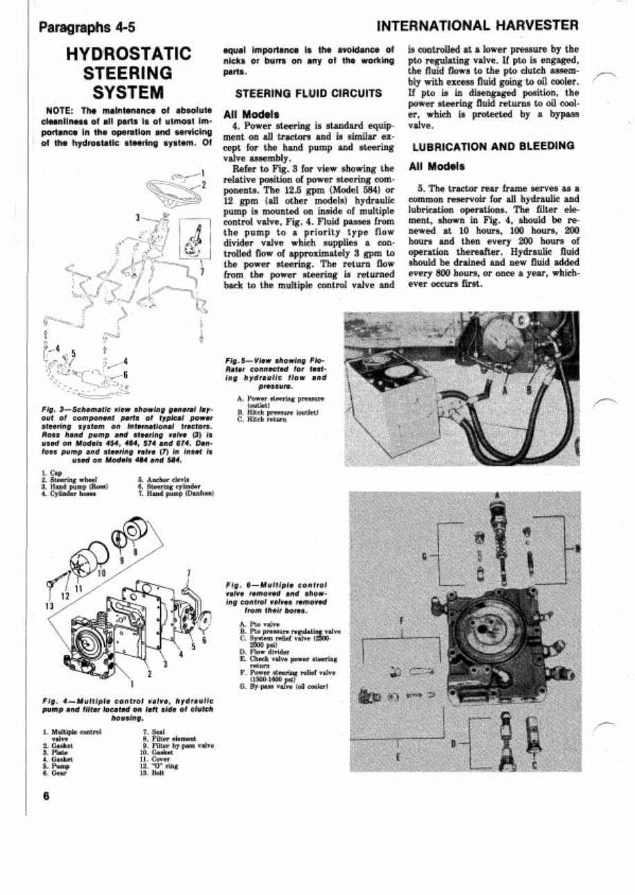
Fig. 3-Schematic view showing general lay-
out of component parts of typical power
steering system on International tractors.
Ross hand pump and steering valve (3) is
used on Models 454, 464, 574 and 674. Dan-
foss pump and steering valve (7) in inset is
used on Models 484 and 584.
INTERNATIONAL HARVESTER
equal importance is the avoidance of is controlled at a lower pressure by the
nicks or burrs on any of the working pto regulating valve. If pto is engaged,
parts. the fluid flows to the pto clutch assem-
bly with excess fluid going to oil cooler.
P
STEERING FLUID CIRCUITS
If pto is in disengaged position, the
power steering fluid returns to oil cool-
All Models er, which is protected by a bypass
4. Power steering is standard equip- valve.
ment on all tractors and is similar ex-
cept for the hand pump and steering LUBRICATION AND BLEEDING
valve assembly.
Refer to Fig. 3 for view showing the
All Models
relative position of power steering com-
ponents. The 12.5 gpm (Model 584) or
5. The tractor rear frame serves as a
12 gpm (all other models) hydraulic
common reservoir for all hydraulic and
pump is mounted on inside of multiple
lubrication operations. The filter ele-
control valve, Fig. 4. Fluid passes from
ment, shown in Fig. 4, should be re-
the pump to a priority type flow
newed at 10 hours, 100 hours, 200
divider valve which supplies a con-
hours and then every 200 hours of
trolled flow of approximately 3 gpm to
operation thereafter. Hydraulic fluid
the power steering. The return flow
should be drained and new fluid added
from the power steering is returned
every 800 hours, or once a year, which-
back to the multiple control valve and
ever occurs first.
Fig. 5- View showing Flo-
Rater connected for test-
ing hydraulic flow and
pressure.
A. Power steering pressure
(outlet)
B. Hitch pressure (outlet)
C. Hitch return
1. Cap
2. Steering wheel 5. Anchor clevis
3. Hand pump (Ross) 6. Steering cylinder
4. Cylinder hoses 7. Hand pump (Danfoss)
Fig. 6-Multiple control
valve removed and show-
ing control valves removed
from their bores.
A. Pto valve
B. Pto pressure regidatin valve
C. System relief valve (400-
2500 psi)
D. Flow divider
E. Check valve power steering
Fig. 4-Multiple control valve, hydraulic
pump and filter located on left side of clutch
housing.
1. Multiple control 7. Seal
valve 8. Filter element
2. Gasket 9. Filter by-pass valve
3. Plate 10. Gasket
4. Gasket 11. Cover
5. Pump 12. "0 ring
6. Gear 13. Bolt
return
F. Power steering relief valve
(1500-1600 si)
G. By-pass vage (oil cooler)
SERlES 454-464-484-574-584-674 Paragraphs 6-1 4
Only IH "Hy-Tran" fluid should be
used and level should be maintained at
n
the "FULL mark shown on level gage
(dipstick). The dipstick is located on
left front side of rear frame.
I Whenever power steering lines have
~
been disconnected, or fluid changed,
~
start engine and cycle power steering
I
system from stop to stop several times
to bleed air from system. Then, check
I
and if necessary, add fluid.
I
i
HYDRAULIC FLOW AND
PRESSURE TEST
I
All Models
~ 6. A flow and pressure test can be
made with a Flo-Rater or equivalent.
Refer to Fig. 5 and connect inlet of Flo-
I
Rater to the outlet of the power steer-
ing and hitch. Then, connect outlet of
Flo-Rater to the return port from the
hitch as shown.
7. HYDRAULIC PUMP. To check
the pump free flow run engine at rated
rpm (2200 on Models 454, 574 or 484,
2900 on Model 584 or 2400 on Models
464 and 674). Restrict the Flo-Rater to
1250 psi and there should be a 12.5
gpm flow on Model 584 or a 12 gpm
flow on all other models.
If pump free flow is not as specified,
p remove and service pump as outlined in
paragraphs 12 and 13.
8. STEERING RELIEF VALVE. To
check the relief valve, restrict the Flo-
Rater to 1500-1600 psi; at this point the
valve should open. If pressure is not as
specified, renew the relief valve assem-
bly (F-Fig. 6) in the multiple control
valve.
9. FLOW DIVIDER. To check the
flow divider, restrict the Flo-Rater to
1500-1600 psi; approximately 2% gpm
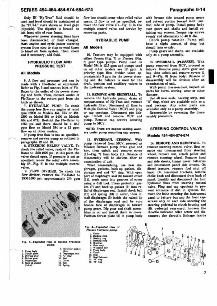
Fig. 7-Exploded view of Cessna hydraulic
pump.
7. Protector gasket
1. Pump body (thin)
2. Thrust plate 8. Diaphragm seal
3. Drmmg gear 9. '0" ring
4. Driven gear 10. Seal
5. Dia hragm 11. Cover
S. B J - u p gasket 12. B~U,
(thick) 13. Sprmg
flow loss should occur when relief valve
opens. If flow is not as specified, re-
move the flow valve (D-Fig. 6) in the
multiple control valve and service by
renewing parts.
HYDRAULIC PUMP
All Models
10. Tractors may be equipped with
either Cessna (Fig. 7) or Plessey (Fig.
8) gear type pumps. Pump used on
Model 584 is 12.5 gpm and pumps used
on all other models are 12 gpm. A
priority type flow divider takes ap-
proximately 3 gpm for the power steer-
ing and the balance is used for the
draft, position and auxiliary valves in
the hydraulic system.
11. REMOVE AND REINSTALL. To
remove the hydraulic pump, drain all
compartments of Hy-Tran and remove
hydraulic filter. Disconnect all lines to
Multiple Control Valve (MCV) and plug
or cap openings. Disconnect pto link-
age. Unbolt and remove MCV and
pump. Remove cap screws securing
pump to MCV.
NOTE: There are copper sealing wash-
ers under pump mounting cap screws.
12. OVERHAUL [CESSNA]. With
pump removed from MCV, proceed as
follows: Remove pump drive gear and
key, then unbolt and remove cover
(11-Fig. 7) from body (1). Balance of
disassembly will be obvious after an
examination of unit.
When reassembling, use new dia-
phragm, gaskets, back-up gasket, dia-
phragm seal and "0 ring. With open
part of diaphragm seal (8) toward cover
(ll), work same into grooves of cover
using a dull tool. Press protector gas-
ket (7) and back-up gasket (6) into re-
lief of diaphragm seal. Install check ball
(12) and spring (13) in cover, then in-
stall diaphragm (5) inside the raised lip
of the diaphragm seal and be sure
bronze face of diaphragm is toward
pump gears. Dip gear and shaft assem-
blies in oil and install them in cover.
Position thrust plate (2) in pump body
with bronze side toward pump gears
and cut-out portion toward inlet (suc-
tion) side of pump. Install pump body
over gears and shafts and install re-
taining cap screws. Torque cap screws
evenly and alternately to 40 ft.-lbs.
Check pump rotation. Pump will
have a slight amount of drag but
should turn evenly.
Pump gears and shafts, are available
only as a pump assembly.
13. OVERHAUL [PLESSEY]. With
pump removed from MCV, proceed as
follows: Remove pump drive gear and
key, then unbolt and remove covers (1
and 9-Fig. 8) from body. Balance of
disassembly will be obvious after an
examination of unit.
With pump disassembled, inspect all
parts for burrs, scoring, wear or other
damage.
I
Use all new seals, backing strip, and
"0 ring, which are available only as a
seal package. Any other parts are
available only as a pump assembly.
Reassemble by reversing the disas-
sembly procedure.
STEERING CONTROL VALVE
Models 454-464-574-674
14. REMOVE AND REINSTALL. To
remove steering control valve, first re-
move cap (monogram) from steering
wheel, remove nut, attach puller and
remove steering wheel. Remove hood
and side sheets, tunnel cover, batteries
and instrument panel side covers. On
diesel tractors, remove fuel shut off
knob. On nondiesel tractors, remove
choke knob and disconnect from back of
panel. Identify and disconnect the four
hydraulic lines from steering control
valve. Plug and cap openings to pre-
vent entrance of dirt in system. Re-
move the bolts securing the instrument
panel to battery box and the front cap-
screws only on each side securing the
steering pedestal to clutch housing and
tilt pedestal rearward. Loosen the
throttle indicator Allen screw and dis-
connect the throttle linkage inside
Fie. 8-Exploded view of 6-23
6
\
fiessey hydraulic pump. J&,)lA
1. Cover
2. Backing strip
3. Sealing ring
4. Backing strip
5. Bearings
6. Gear assy.
7. Woodruff key
8. Pump body
9. Cover
in Seal
12. '0" ring
13. "0 ring
- - . - ---
11. Seal Retainer
INTERNATIONAL HARVESTER
steering eolumn. With throttle shaft NOTE: Lapped surfaces of end cover
card seal ring (10). Slide upper cover
between high and low speed, push the
(38), commutator set (33 and 34), mani- assembly from input shaft and remove
handle d ~ w n to compress the spring. fold (32). stator-rotor set (31), spacer Teflon spacer (16). Remove shims (12)
Clamp the shaft using vise grip pliers,
(29) and valve body (25) must be pro- from cavity in upper cover or from face
then drive the two bottom roll pins out. tected from scratching, burring or any
of thrust washer (14) and note number
Release the vise grip pliers and remove
other damage as sealing of these parts of shims for aid in reassembly. Remove
the remaining roll pin. Remove the four depends on their finish and flatness. snap ring (41, stepped washer (51, brass
cap screws securing instrument panel
washer (61, Teflon washer (7) and seal
to the support assembly and move the Remove seal retainer (35) and seal
(8). Retain stepped washer (5) and snap
panel to the side. Remove the cap (361, then carefully remove washer (371, ring (4) for reassembly. Do not remove
screws securing steering control valve commutator set (33 and 34) and mani- needle bearing (11) as it is not serviced
and remove valve. fold (32). Grasp spacer (29) and lift off separately.
Reinstall by reversing the removal
the spacer, drive link (30) and stator- Remove snap ring (13), thrust wash-
procedure; then bleed hydraulic system rotor set (31) as an assembly. Separate ers (14) and thrust bearing (15) from
as outlined in paragraph 5. spacer and drive link from stator-rotor input shaft. Drive out pin (18) and
set.
withdraw torsion bar (21) and spacer
15. OVERHAUL. To disassemble the Remove unit from vise, then clamp (20). Place end of valve spool on top of
removed steering control valve assem- fitting in vise so that input shaft is
bench and rotate input shaft until drive
bly, refer to Fig. 9 and proceed as fol- pointing upward. Remove water and ring (19) falls free, then rotate input
lows: Install a fitting in one of the four dirt seal (2) and felt seal (3). Place a shaft clockwise until actuator ball (23)
ports in valve body (251, then clamp light mark on flange of upper cover (9) is disengaged from helical groove in in-
fitting in a vise so that input shaft (17) and valve body (25) for aid in reassem- put shaft. Withdraw input shaft and re-
is pointing downward. Apply match bly. Unbolt upper cover from valve move actuator ball. Do not remove ac-
marks across end cover and valve body body, then grasp input shaft and re- tuator ball retaining spring (24) unless
for aid in reassembly. Remove cap
move input shaft, upper cover and renewal is required.
screws (39) and end cover (38). valve spool assembly. Remove and dis- Remove plug (28) and recirculating
ball (26) from valve body.
Thoroughly clean all parts in a suit-
able solvent, visually inspect parts and
renew any showing excessive wear,
scoring or other damage.
If needle bearing (11) is excessively
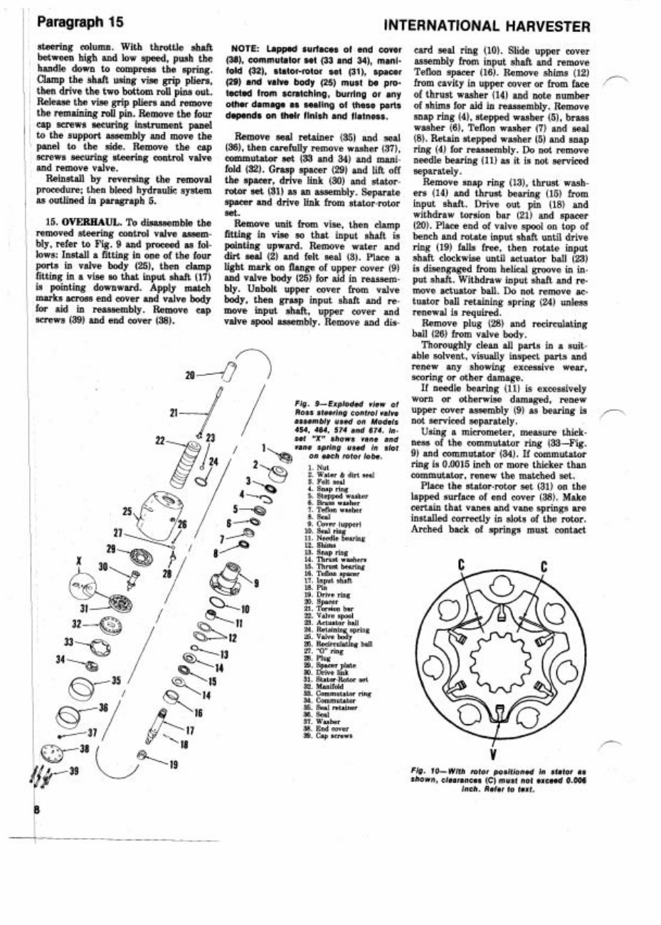
Fig. 9-Exploded view of
worn or otherwise damaged, renew
ROSS steering control valve
upper cover assembly (9) as bearing is
,-
assembly used on Models not serviced separately.
454, 464, 574 and 674. In-
Using a micrometer, measure thick-
set "'" vane and ness of the commutator ring (=-Fig.
vans spring used in slot
on each rotor lobe.
9) and commutator (34). If commutator
ring is 0.0015 inch or more thicker than
2. Water & dirt seal commutator, renew the matched set.
Place the stator-rotor set (31) on the
5. Stepped washer
6. Brass washer
lapped surface of end cover (38). Make
7. Teflon washer
certain that vanes and vane springs are
9. Cover (upper)
installed correctly in slots of the rotor.
10. Seal ring
Arched back of springs must contact
11. Needle bearing
12. Shims
13. Snap ring
14. Thrust washers
15. Thrust bearing
19. Drive ring
20. Spacer
21. Torsion bar
22. Valve spool
28. Plug
B. Spacer plate
30. Drive link
31. Stator-Rotor set
32. Manifold
33. Commutator ring
34. Commutator
35. Seal retainer
36. Seal
37. Washer
38. End wver
39. Cap screws
V
Fig. 10-With rotor positioned in stator as
shown, clearances (C) must not exceed 0.006
inch. Refer to text.
SERl ES 454-464-484-574-584-674 Paragraphs 16-1 7
vanes. See inset X-Fig. 9. Position
lobe of rotor in valley of stator as
shown at (V-Fig. 10). Center opposite
lobe on crown of stator, then using two
feeler gages, measure clearance (C)
between rotor lobes and stator. If clear-
ance is more than 0.006 inch, renew
stator-rotor assembly. Using a microm-
eter, measure thickness of stator and
rotor. If stator is 0.002 inch or more
thicker than rotor, renew the assembly.
Stator, rotor, vanes and vane springs
are available only as an assembly.
Before reassembling, wash all parts
in clean solvent and air dry. All parts,
unless otherwise indicated, are in-
stalled dry. Install recirculating ball
(26-Fig. 9) and plug (28) with new "0
ring (27) in valve body and tighten plug
to a torque of 10-14 ft.-lbs. Clamp
fitting (installed in valve body port) in
a vise so that top end of valve body is
facing upward. Install thrust washer
(14). thrust bearing (15), second thrust
washer (14) and snap ring (13) on input
shaft (17). If actuator ball retaining
ring (24) was removed, install new re-
taining ring. Place actuator ball (23) in
its seat inside valve spool (22). Insert
input shaft into valve spool, engaging
the helix and actuator ball with a
counterclockwise motion. Use the mid-
section of torsion bar (21) as a gage be-
tween end of valve spool and thrust
washer, then place the assembly in a
vertical position with end of input shaft
resting on a bench. Insert drive ring
(19) into valve spool until drive ring is
engaged on input shaft spline. Remove
torsion bar gage. Install spacer (20) on
torsion bar and insert the assembly
into valve spool. Align crossholes in
torsion bar and input shaft and install
pin (18). Pin must be pressed into shaft
until end of pin is about 1132-inch be-
low flush. Place spacer (16) over spool
and install spool assembly into valve
body. Position original shims (12) on
thrust washer (141, lubricate new seal
ring (10). place seal ring in upper cover
(9) and install upper cover assembly.
Align the match marks on cover flange
and valve body and install cap screws
finger tight. Tighten a worm drive type
hose clamp around cover flange and
valve body to align the outer dia-
meters, then tighten cap screws to a
torque of 18-22 ft.-lbs.
NOTE: If either input shaft (17) or
upper cover (9) or both have been re-
newed, the following procedure for
shimming must be used. With upper
cover installed (with original shims) as
outlined above, invert unit in vise so
that input shaft is pointing downward.
Grasp input shaft, pull downward and
prevent It from rotating. Engage drive
link (30) spllnes in valve spool and ro-
tate drive link until end of spool is flush
with end of valve body. Remove drive
link and check alignment of drive link
slot to torsion bar pin. Install drive link
until its slot engages torsion bar pin.
Check relationship of spool end to body
end. If end of spool is within 0.0025
inch of being flush with end of body,
no additional shimming is required. It
not within 0.0025 inch of being flush,
remove cover and add or remove shims
(12) as necessary. Reinstall cover and
recheck spool to valve body position.
With drive link installed, place
spacer plate (29) on valve body with
plain side up. Install stator-rotor set
over drive link splines and align cap
screw holes. Make certain vanes and
vane springs are properly installed. In-
stall &mifold (32)' with circular slotted
side up and align cap screw holes with
stator, spacer and valve body. Install
commutator ring (33) with slotted side
up, then install commutator (34) over
drive link end making certain that link
end is engaged in the smallest elon-
gated hole in commutator. Install seal
(36) and retainer (35). Apply a few
drops of hydraulic fluid on commutator.
Use a small amount of grease to stick
washer (37) in position over pin on end
cover (38). Install end cover making
sure that pin engages center hole in
commutator. Align holes and install cap
screws (39). Alternately and progres-
sively tighten cap screws while rotat-
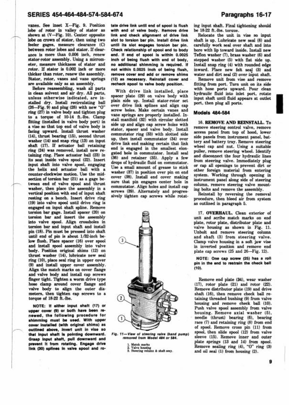
Fig. 11-View of steering valve (hand pump)
removed from Model 484 or 584.
1. Mateh marks
2. Valve housing
3. Steering mlumn & shaft assy.
ing input shaft. Final tightening should
be 18-22 ft.-lbs. toraue.
Relocate the unit in vise so input
shaft is up. Lubricate new seal (8) and
carefully work seal over shaft and into
bore with lip toward inside. Install new
Teflon washer (7). brass washer (6) and
stepped washer (5) with flat side up.
Install snap ring (4) with rounded edge
inward. Place new felt sea? (3) and
water and dirt seal (2) over input shaft.
Remove unit from vise and remove
fitting from port. Turn unit on its side
with hose ports upward. Pour clean
hydraulic fluid into inlet port, rotate
input shaft until fluid appears at outlet
port, then plug all ports.
Models 484-584 1
16. REMOVE AND REINSTALL. To
remove steering control valve, remove
access panel from top of hood, lower
side panels from instrument panel, bat-
tery and battery tray. Remove steering
wheel cap and nut. Using a suitable
puller, remove steering wheel. Identify
and disconnect the four hydraulic lines
from steering valve. Immediately plug
or cap all openings to prevent dirt or
other foreign material from entering
system. Working through opening in
instrument panel along side of steering
column, remove steering valve mount-
ing bolts and remove the assembly.
Reinstall by reversing the removal
~rocedure. then bleed air from svstem
i s outlined in paragraph 5.
17. OVERHAUL. Clean exterior of
unit and scribe match marks on end
plate, rotor plate, distributor plate and
valve housing as shown in Fig. 11.
Unbolt and remove steering column
and shaft (3) from steering valve.
Clamp valve housing in a soft jaw vise
in inverted position and remove end
plate cap screws (25 and 26-Fig. 12).
NOTE: One cap screw (25) has a roll
pin in the end to restrain the check ball
(10).
Remove end plate (a), wear washer
(171, rotor plate (21) and rotor (22).
Remove distributor plate (19) and drive
shaft (16). then remove check ball re-
taining threaded bushing (9) from valve
housing and remove check ball (10).
Push valve spool assembly from valve
housing. Remove axial washer (5),
needle (thrust) bearing (6). bearing
race (7) and retaining ring (8) from end
of spool. Remove cross pin (11) from
spool, then slide spool (12) from valve
sleeve (15). Remove inner and outer
plate springs (13 and 14) from spool.
Remove sealing ring (4), "0 ring (3)
and oil seal (1) from housing (2).
l 1
1 Paragraph 18
(
Clean and inspect all parts and re-
, new any showing excessive wear or
1
other damage. If housing (2). spool (12)
I or sleeve (15) are not suitable for
further service, renew complete assem-
I bly as these parts are not serviced sep-
1 ' arately. All "0 rings and seals are
I available in a seal kit. Lubricate all
! internal parts with Hy-Tran Fluid and
coat all "0 rings with vaseline. Reas-
semble by reversing the disassembly
rocedure. Install two outer plate
four inner plate
s shown in Fig. 13. Use eross-
view (Fig. 14) as a guide
ssembling. Align the previous-
ed match marks and tighten
o a torque of 260-
steering column
and upper shaft assembly.
STEERING CYLINDER
All Models
18. R&R AND OVERHAUL. To re-
move the power steering cylinder, dis-
connect and immediately plug the hy-
draulic lines. Remove cap screws from
cylinder support arms (center steering
arm) and separate arms to free cylin-
der. Remove pin retaining anchor clevis
to axle main member and remove cyl-
inder assembly from tractor.
With cylinder removed, move piston
rod back and forth several times to
clear oil from cylinder. Place cylinder
in a vise and clamp vise only enough to
prevent cylinder from turning. Using a
wrench in the flats of piston rod, re-
move the anchor clevis on one end and
w
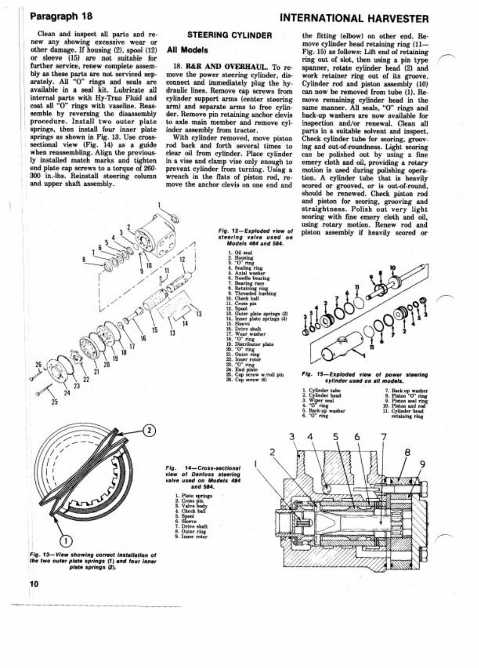
Fig. 13- View showing correct installation of
the two outer plate springs (1) and four inner
plate springs (2).
INTERNATIONAL HARVESTER
Fig. 12-Exploded view of
steering valve used on
Models 484 and 584.
1. Oil seal
2. Housing
3. "0 ring
4. Sealing ring
5. Axial washer
6. Needle bearing
7. Bearing race
8. Retaining rin
9. Threaded bus%ing
10. Check ball
11. Cross pin
12. Spool
13. Outer plate springs (2)
14. Inner plate springs (4)
15. Sleeve
16. Drive shaft
17. Wear washer
18. "0" ring
19. Distributor plate
20. "0 ring
21. Outer ring
22. Inner rotor
23. "0" ring
24. End plate
25. Cap screw w/roll pin
26. Cap screw (6)
Fig. 74-Cross-sectional
view of Danfoss steering
valve used on Models 484
and 584.
1. Plate springs
2 Cross in
3: Valve L y
4. Check ball
5. Spool
6. Sleeve
7. Drive shaft
8. Outer ring
9. Inner rotor
the fitting (elbow) on other end. Re-
move cylinder head retaining ring (11-
Fig. 15) as follows: Lift end of retaining
n
ring out of slot, then using a pin type
,
spanner, rotate cylinder head (2) and
work retainer ring out of its groove.
Cylinder rod and piston assembly (10)
can now be removed from tube (1). Re-
move remaining cylinder head in the
same manner. All seals, "0 rings and
back-up washers are now available for
inspection and/or renewal. Clean all
parts in a suitable solvent and inspect.
Check cylinder tube for swring, groov-
ing and out-of-roundness. Light scoring
can be polished out by using a fine
emery cloth and oil, providing a rotary
motion is used during polishing opera-
tion. A cylinder tube that is heavily
scored or grooved, or is out-of-round,
should be renewed. Check piston rod
and piston for scoring. grooving and
straightness. Polish out very light
scoring with fine emery cloth and oil,
using rotary motion. Renew rod and
piston assembly if heavily scored or
Fig. 15-Exploded view of power steering
cylinder used on all models.
1. Cylinder tube 7. Back-up washer
2. Cylinder head 8. Piston "0 ring
3. Wiper seal 9. Piston seal ring
4. "0' ring 10. Piston and rod
5. Back-up washer 11. Cylinder head
6. "0 ring retaining ring
You're Reading a Preview
What's Included?
Fast Download Speeds
Online & Offline Access
Access PDF Contents & Bookmarks
Full Search Facility
Print one or all pages of your manual
$31.99
Viewed 48 Times Today


Secure transaction
What's Included?
Fast Download Speeds
Online & Offline Access
Access PDF Contents & Bookmarks
Full Search Facility
Print one or all pages of your manual
$31.99
- The IH International Harvester 674 Workshop Repair Service Manual is a comprehensive resource designed to provide all the necessary information for servicing, maintaining, and troubleshooting the IH International Harvester 674.
- This manual covers all models, engines, trim, and transmission types, ensuring access to accurate and complete information.
- Written by the manufacturers, it contains detailed diagrams and instructions for repairing specific components, covering every aspect from the engine to the electrical system.
- It provides step-by-step repair procedures, critical specifications, illustrations, and pictures to guide through each repair process, suitable for professional technicians and DIY enthusiasts.
- The manual includes detailed sections on the engine, lubrication system, cooling system, fuel system, disassembly and servicing, general maintenance, and advanced troubleshooting, along with a comprehensive wiring diagram.
- Available in electronic format, it offers easy access from a computer, allowing for printing of desired sections and instant download.
- Both the paper and electronic versions offer the same features and information, with the electronic version providing instant access and download to a computer within seconds.
- Investing in this manual will save money on repair costs and help properly maintain the IH International Harvester 674 for years to come.
- Don't miss out on this opportunity to have a complete and reliable manual at your fingertips. Get your IH International Harvester 674 Workshop Repair Service Manual today and take control of your vehicle's maintenance and repairs.


