IH International Harvester 2424 Workshop Service Manual
What's Included?
Lifetime Access
Fast Download Speeds
Online & Offline Access
Access PDF Contents & Bookmarks
Full Search Facility
Print one or all pages of your manual
WORKSHOP MANUAL OVER INTERNATIONAL HARVESTER TRAKTOR MODEL B275-B414 354-364-384 424-444 2424-2444
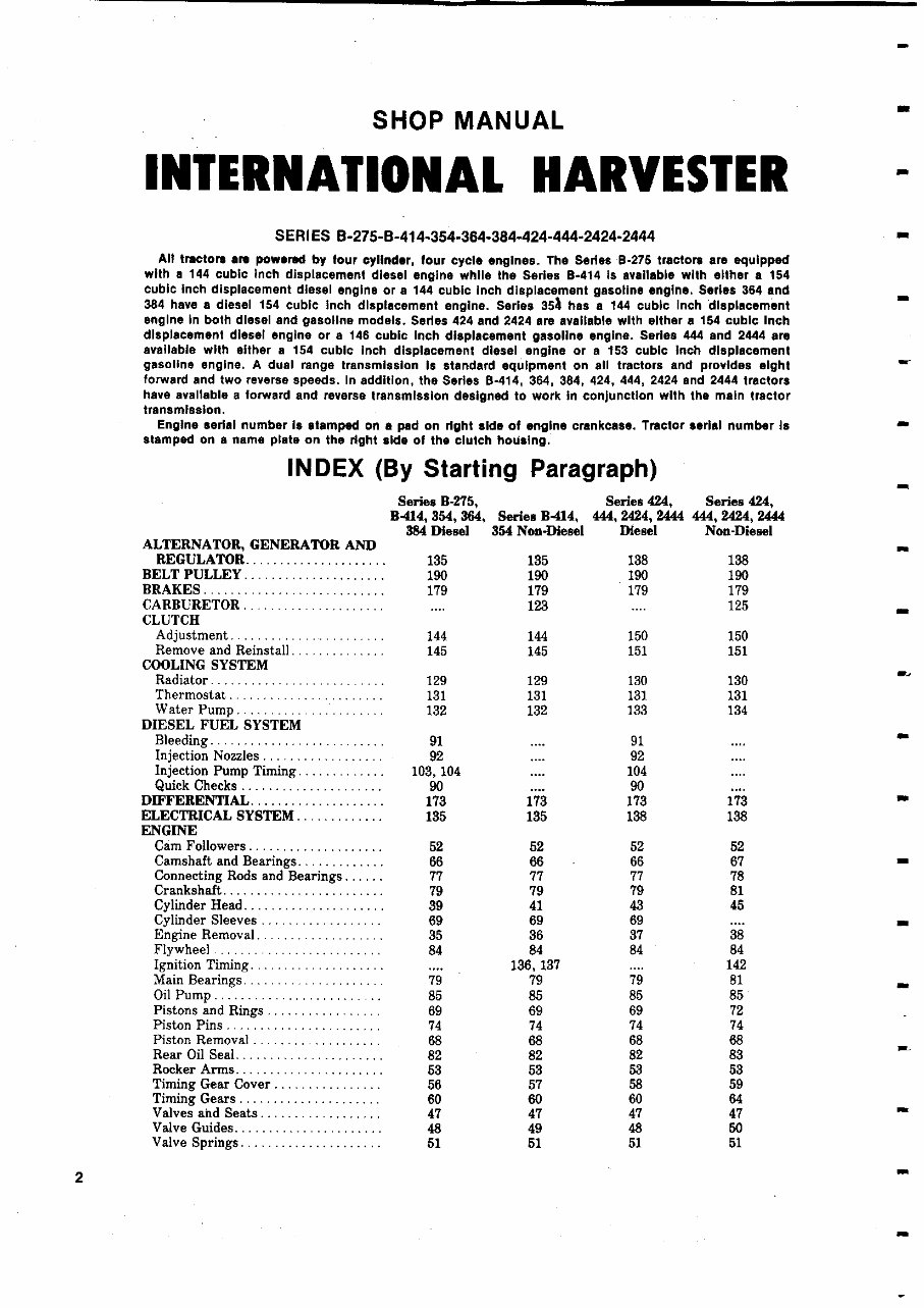
SHOP MANUAL INTERNATIONAL HARVESTER SERIES B-275 - B-414- 354-364 - 384-424 - 444-2424-2444 All tractors are powered by four cylinder , four cycle engines . The Series B-275 tractors are equipped with a 144 cubic Inch displacement diesel engine while the Series B - 414 Is available with either a 154 cubic Inch displacement diesel engine or a 144 cubic Inch displacement gasoline engine . Series 364 and 384 have a diesel 154 cubic inch displacement engine . Series 354 has a 144 cubic Inch displacement engine in both diesel and gasoline models . Series 424 and 2424 are available with either a 154 cubic Inch displacement diesel engine or a 146 cubic Inch displacement gasoline engine . Series 444 and 2444 are available with either a 154 cubic Inch displacement diesel engine or a 153 cubic Inch displacement gasoline engine . A dual range transmission is standard equipment on all tractors and provides eight forward and two reverse speeds . In addition , the Series 8-414 , 364, 384 , 424, 444 , 2424 and 2444 tractors have available a forward and reverse transmission designed to work in conjunction with the main tractor transmission. Engine serial number Is stamped on a pad on right side of engine crankcase . Tractor serial number Is stamped on a name plate on the right aide of the clutch housing. INDEX ( By Starting Paragraph) Series B-275, B-414, 354, 364 , 384 Diesel Series 8414, 354 Non -Diesel Series 424, 444, 2424 , 2444 Diesel Series 424, 444 , 2424, 2444 Non -Diesel ALTERNATOR , GENERATOR AND REGULATOR ..................... 135 135 138 138 BELT PULLEY ..................... 190 190 190 190 BRAKES ........................... 179 179 179 179 CARBURETOR ..................... .... 123 .... 125 a CLUTCH Adjustment ....................... 144 144 150 150 Remove and Reinstall . ............. 145 145 151 151 COOLING SYSTEM Radiator .......................... 129 129 130 130 Thermostat ....................... 131 131 131 131 Water Pump ..................... 132 132 133 134 DIESEL FUEL SYSTEM Bleeding .......................... 91 .... 91 a Injection Nozzles .................. 92 .... 92 .... Injection Pump Timing ............. 103, 104 .... 104 Quick Checks ..................... 90 90 .... DIFFERENTIAL .................... 173 173 173 173 ELECTRICAL SYSTEM ............. 135 135 138 138 ENGINE Cam Followers .................... 52 52 52 52 Camshaft and Bearings ............. 66 66 66 67 Connecting Rods and Bearings ...... 77 77 77 78 Crankshaft ........................ 79 79 79 81 Cylinder Head ..................... 39 41 43 45 Cylinder Sleeves .................. 69 69 69 .... Engine Removal ................... 35 36 37 38 Flywheel ...... ........... 84 84 84 84 Ignition Timing .................... .... 136, 137 .... 142 Main Bearings ..................... 79 79 79 81 Oil Pump. -- ................ - 85 85 85 85 Pistons and Rings ................. 69 69 69 72 Piston Pins ....................... 74 74 74 74 Piston Removal ................... 68 68 68 68 Rear Oil Seal ...................... 82 82 82 83 Rocker Arms ...................... 53 53 53 53 Timing Gear Cover ................ 56 57 58 59 Timing Gears ..................... 60 60 60 64 Valves and Seats .................. 47 47 47 47 Valve Guides ...................... 48 49 48 50 Valve Springs ..................... 51 51 51 51 2
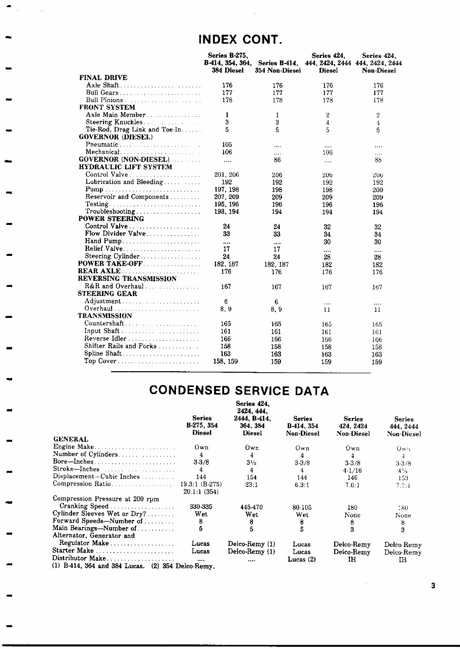
INDEX CONT. Series B-275, Series 424, Series 424, B-414, 354, 364 , Series B-414 , 444, 2424, 2444 444, 2424, 2444 384 Diesel 354 Non - Diesel Diesel Non - Diesel FINAL DRIVE Axle Shaft ....................... 176 176 176 176 Bull Gears ...................... 177 177 177 177 Bull Pinions. . .... ... ............ 178 178 178 178 FRONT SYSTEM Axle Main Member ................ 1 1 2 2 Steering Knuckles. ................ 3 3 4 4 Tie-Rod, Drag Link and Toe-In ..... 5 5 5 5 GOVERNOR (DIESEL) Pneumatic ....................... 105 .... .... .... Mechanical ......... ............. 106 .... 106 GOVERNOR (NON-DIESEL) ......... .... 86 .... 88 HYDRAULIC LIFT SYSTEM Control Valve. ... _ .............. 201, 206 206 206 206 Lubrication and Bleeding. .... ..... 192 192 192 192 Pump . ........................... 197,198 198 198 200 Reservoir and Components ........ 207, 209 209 209 209 Testing .......................... 195,196 196 196 196 Troubleshooting ................... 193,194 194 194 194 POWER STEERING Control Valve ..................... 24 24 32 32 Flow Divider Valve ................ 33 33 34 34 Hand Pump ....................... .... .... 30 30 Relief Valve ................. .... 17 17 .... .... Steering Cylinder .................. 24 24 28 28 POWER TAKE-OFF.. . ..... ....... 182, 187 182, 187 182 182 REAR AXLE ...................... 176 176 176 176 REVERSING TRANSMISSION R&R and Overhaul ............... 167 167 167 167 STEERING GEAR Adjustment ..... ............... 6 6 .... .... Overhaul ......................... 8,9 8,9 11 11 TRANSMISSION Countershaft.... .......... 165 165 165 165 Input Shaft .......... ...... 161 161 161 161 Reverse Idler ..................... 166 166 166 166 Shifter Rails and Forks ............ 158 158 158 158 Spline Shaft ....................... 163 163 163 163 Top Cover ...................... 158,159 159 159 159 CONDENSED SERVICE DATA GENERAL Series 424, 2424,444, Series 2444 , B-414 , Series Series Series B-275 , 354 364 , 384 B-14, 354 424, 2424 444, 2444 Diesel Diesel Non-Diesel Non-Diesel Non -Diesel Engine Make .................... Own Own Own Own Own Number of Cylinders ................ 4 4 4 4 4 Bore-Inches .. . ........ . ......... 3-3/8 31 /2 3-3/8 3-3 /8 3-3/8 Stroke-Inches .................. 4 4 4 4-1/16 44d Displacement - Cubic Inches ........ 144 154 144 146 153 Compression Ratio . .................. 19.3:1 (B-275 ) 23:1 6.3:1 7.6 :1 7.7:1 20.1:1 (354) Compression Pressure at 200 rpm Cranking Speed ................... 330-335 445-470 80-105 180 _ 180 Cylinder Sleeves Wet or Dry? ........ Wet Wet Wet None None Forward Speeds-Number of ......... 8 8 8 8 8 Main Bearings-Number of ........... 5 5 5 3 3 Alternator, Generator and Regulator Make ................... Lucas Delco-Remy (1) Lucas Delco-Remy Delco-Remy Starter Make ....................... Lucas Delco-Remy (1) Lucas Delco-Remy Delco-Remy Distributor Make .................... .... .... Lucas (2) IH IH ( 1) B414, 364 and 384 Lucas . ( 2) 354 Delco-Remy. 3
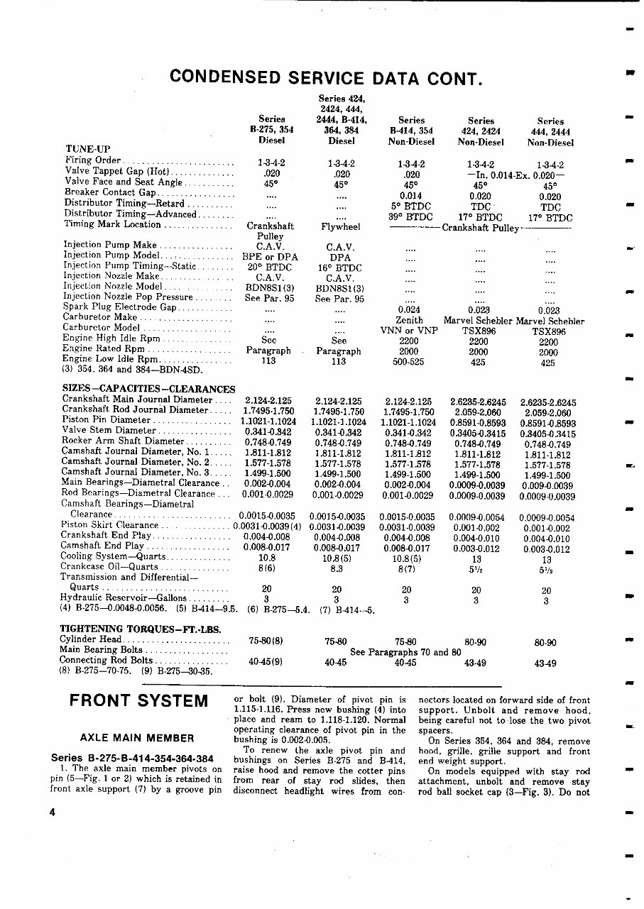
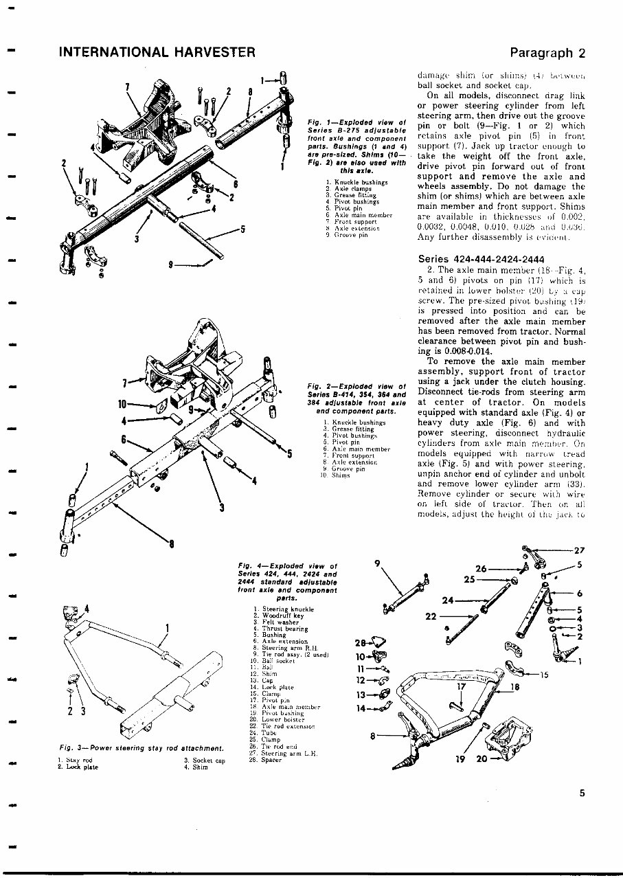
CONDENSED SERVICE DATA CONT. Series 424, Series B-275, 354 Diesel 2424,444, 2444, B-414, 364, 384 Diesel TUNE-UP Firing Order. . ...................... 134-2 13-0-2 Valve Tappet Gap (Hot) .............. .020 .020 Valve Face and Seat Angle.......... 450 450 Breaker Contact Gap ................. .... .... Distributor Timing-Retard .......... .... .... Distributor Timing-Advanced.. . ..... .... .... Timing Mark Location ............... Crankshaft Flywheel Injection Pump Make ................ Pulley C.A.V. C.A.V. Injection Pump Model ... ............ BPE or DPA DPA Injection Pump Timing-Static ...... 20° BTDC 16° BTDC Injection Nozzle Make. . ... ......... C.A.V. C.A.V. Injection Nozzle Model. .............. BDN8S1(3) BDN8S1(3) Injection Nozzle Pop Pressure ........ See Par. 95 See Par. 95 Spark Plug Electrode Gap........... .... .... Carburetor Make ................. .. .... .... Carburetor Model ........ _ ..... .. .... .... Engine High Idle Rpm ............. See See Engine Rated Rpm ................. Paragraph Paragraph Engine Low Idle Rpm ............ .. 113 113 (3) 354, 364 and 384-BDN4SD. SIZES - CAPACITIES - CLEARANCES Crankshaft Main Journal Diameter .... 2.124 -2.125 2 . 124-2.125 Crankshaft Rod Journal Diameter ..... 1.7495-1.750 1.7495-1.750 Piston Pin Diameter ................. 1.1021-1.1024 1.1021-1.1024 Valve Stem Diameter ................ 0.341-0.342 0.341-0.342 Rocker Arm Shaft Diameter .......... 0.748-0.749 0.748-0.749 Camshaft Journal Diameter, No. 1 ..... 1. 811-1 .812 1.811-1.812 Camshaft Journal Diameter , No. 2..... 1.577-1.578 1.577-1.578 Camshaft Journal Diameter, No. 3..... 1. 499-1 . 500 1 .499-1.500 Main Bearings-Diametral Clearance .. 0.002-0 .004 0.002-0.004 Rod Bearings-Diametral Clearance ... 0.001-0.0029 0.001-0.0029 Camshaft Bearings-Diametral Clearance.... 0.0015-0.0035 Piston Skirt Clearance ............... 0.0031-0.0039(4) Crankshaft End Play ................ 0.004-0.008 Camshaft End Play .................. 0.008-0.017 Cooling System-Quarts. ............. 10.8 Crankcase Oil-Quarts ............ 8(6) Transmission and Differential- Quarts ........................... 20 Hydraulic Reservoir-Gallons......... 3 Series Series Series B-414 , 354 424, 2424 444, 2444 Non - Diesel Non-Diesel Non-Diesel 134-2 1-3-4-2 1-34-2 .020 -In . 0.014 - Ex. 0.020- 450 450 450 0.014 0 . 020 0.020 50 BTDC TDC TDC 390 BTDC 17 ° BTDC 17° BTDC Crankshaft Pulley 0.024 0 . 023 0.023 Zenith Marvel Schebler Marvel Schebler VNN or VNP TSX896 T5X896 2200 2200 2200 2000 2000 2000 500-525 425 425 2.124 - 2.125 2 . 6235 -2.6245 2 . 6235 -2.6245 1.7495-1.750 2.059-2.060 2.059-2.060 1.1021-1.1024 0.8591-0.8593 0.8591-0.8593 0.341-0.342 0.3405-0.3415 0.3405-0.3415 0.748-0.749 0.748-0.749 0.748-0.749 1.811-1.812 1.811-1.812 1.811-1.812 1.577-1.578 1.577-1.578 1.577-1.578 1.499-1.500 1.499-1.500 1.499-1.500 0.002-0.004 0.0009-0.0039 0.009-0.0039 0.001-0.0029 0.0009-0.0039 0.0009-0.0039 0.0015-0.0035 0.0015-0.0035 0.0009-0.0054 0.0009-0.0054 0.0031-0.0039 0.0031-0.0039 0.001-0.002 0.001-0.002 0.004-0.008 0.004-0.008 0.004-0.010 0.004-0.010 0.008-0.017 0.008-0.017 0.003-0.012 0.003-0.012 10.8(5) 10.8(5) 13 13 8.3 8(7 ) 52/2 52/2 20 20 20 20 3 3 3 3 (7) B-014-5. (4) B-2751.0048- 0.0056 . (5) B414-9.5. (6) B -275.4. TIGHTENING TORQUES-FT.-LBS. Cylinder Head ....................... 75-80(8) Main Bearing Bolts .................. Connecting Rod Bolts ................ 40115(9) (8) B-275-70-75. (9) 8-275-3035. FRONT SYSTEM AXLE MAIN MEMBER Series B-275-B - 414-354 - 364-384 1. The axle main member pivots on pin (5-Fig. 1 or 2) which is retained in front axle support (7) by a groove pin 75-80 75-80 80-90 80-90 See Paragraphs 70 and 80 40-45 40-45 43-49 43119 or bolt (9). Diameter of pivot pin is 1.115-1.116. Press new bushing (4) into place and ream to 1.118-1.120. Normal operating clearance of pivot pin in the bushing is 0.002-0.005. To renew the axle pivot pin and bushings on Series B-275 and B-014, raise hood and remove the cotter pins from rear of stay rod slides, then disconnect headlight wires from con- nectors located on forward side of front support. Unbolt and remove hood, being careful not to lose the two pivot spacers. On Series 354, 364 and 384, remove hood, grille, grille support and front end weight support. On models equipped with stay rod attachment, unbolt and remove stay rod ball socket cap (3-Fig. 3). Do not ,r S 4
INTERNATIONAL HARVESTER Fig. 3-Power steering stay rod attachment. 1. Stay rod 3. Socket cap 2. Loa plate 4. Shim Fig. 1-Exploded view of Series B - 275 adjustable front axle and component parts . Bushings ( 1 and 4) are pro - sized. Shims (10- Fig. 2) are also used with this axle. 1. Knuckle bushings 2. Axle clamps 3. Grease fitting 4. Pivot bushings 5. Pivot the 6. Axle main member 7. Front support 8 Axle extension 9. Groove pin Fig. 2-Exploded view of Series B-414 , 354, 364 and 384 adjustable front axle and component parts. 1. Knuckle bushings 3. Grease fitting 4. Pivot bushings 5. Pivot pin 6. Axle main member 7. Front support 8. Axle extension 5. Groove pin 10. Shims Fig. 4-Exploded view of Series 424 , 444, 2424 and 2444 standard adjustable front axle and component parts. 1. Steering knuckle 2. Woodruff key 3. Felt washer 4. Thrust bearing 5. Bushing 6. Axle extension 8. Steering arm R.H. 9 Tie rod asst'. (2 used) 10. Ball so ket ll. Ball 12. Shim 3. Cap 14. Lock plate 3s. Camp 17. Pivot pin t8. Axle main member , 19. Pivot bushing 20. Lower bolster 22. 'Vie rod extension 24. Tube 25. Clamp 26, Tie rod end 27. Steering arm LH. 28. Spacer Paragraph 2 damage shim (or shims) 141 On)ivc 1, ball socket and socket cap. On all models, disconnect drag link or power steering cylinder from left steering arm, then drive out the groove pin or bolt (9-Fig. 1 or 2) which retains axle pivot pin (5) in front support (7). Jack up tractor enough to take the weight off the front axle, drive pivot pin forward out of front support and remove the axle and wheels assembly. Do not damage the shim (or shims ) which are between axle main member and front support. Shims are available in thicknesses of 0.002, 0.0032, 0,0048, 0.010, 0.028 and 0.u36. Any further disassembly is evident. Series 424 - 444-2424-2444 2. The axle main member (18 Fig. 4, 5 and 6) pivots on pin (17) which is retained in lower holster (20) by a cap screw. The pre-sized pivot bushing (191 is pressed into position and can be removed after the axle main member has been removed from tractor . Normal clearance between pivot pin and bush- ing is 0.008-0.014. To remove the axle main member assembly, support front of tractor using a jack under the clutch housing. Disconnect tie-rods from steering arm at center of tractor. On models equipped with standard axle (Fig. 4) or heavy duty axle ( Fig. 6 ) and with power steering, disconnect hydraulic cylinders from axle main member. On models equipped with narrow tread axle (Fig. 5) and with power steering, unpin anchor end of cylinder and unbolt and remove lower cylinder arm (33). Remove cylinder or secure with wire on left side of tractor. Then on all models, adjust the height of the jack to 27 25 26 -^ / ' S --^® 6 24--x/ e p 4 3 15 5
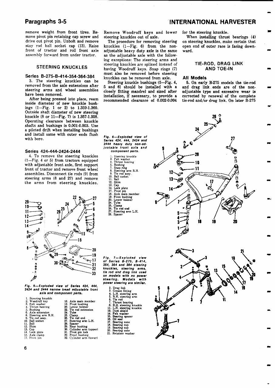
Paragraphs 3-5 remove weight from front tires. Re- move pivot pin retaining cap screw and drive out pivot pin. Unbolt and remove stay rod ball socket cap (13 ). Raise front of tractor and roll front axle assembly forward from under tractor. STEERING KNUCKLES Series B-275-B - 414-354 - 364-384 3. The steering knuckles can be removed from the axle extensions after steering arms and wheel assemblies have been removed. After being pressed into place, ream inside diameter of new knuckle bush- ings ( 1-Fig . 1 or 2 ) to 1.359 - 1.360. Outside shaft diameter of new steering knuckle ( 8 or 11-Fig . 7) is 1 . 357-1.358. Operating clearance between knuckle shafts and bushings is 0.001-0 . 003. Use a piloted drift when installing bushings and install same with outer ends flush with bore. Series 424 - 444-2424-2444 4. To remove the steering knuckles (1-Fig. 4 or 5) from tractors equipped with adjustable front axle, first support front of tractor and remove front wheel assemblies . Disconnect tie rods ( 9) from steering arms ( 8 and 27 ) and remove the arms from steering knuckles. 0 32 33 "INTERNATIONAL HARVESTER Remove Woodruff keys and lower steering knuckles out of axle. The procedure for removing steering knuckles ( 1-Fig. 6) from the non- adjustable heavy duty axle is the same as the adjustable axle with the follow- ing exceptions : The steering arms and steering knuckles are splined instead of having Woodruff keys . Snap rings (7) must also be removed before steering knuckles can be removed from axle. Steering knuckle bushings ( 5-Fig. 4, 5 and 6) should be installed with a closely fitting mandrel and sized after installation , if necessary , to provide a recommended clearance of 0.002-0.004 Fig. 6-Exploded view of Series 424, 444 , 2424 and 2444 heavy duty non-ad- justable front axle and component parts. 1. Steering knuckle 3. Felt washer 4. Thrust bearing 5. Bushing 7. Snap rung 8. Steering arm R.H. 9. Tie rod ssay. 10. Bell socket 11. Ball 12. Shim 13. Cap 14. Lock plate I7. Pivot pin 18. Axle main member 19. Pivot bushing 20. Lower bolster 24. Tube 25. Clamp 26. Tie rod end 27. Steering arm L.H. 28. Spacer Fig. 7-Exploded view of Series B-275, 8-414, 354, 364 and 384 steering knuckles, steering arms, tie rod and drag link used on models with no power steering. Models with power steering are similar. Fig. 5-Exploded view of Series 424, 444, 2 D 2424 and 2444 narrow tread adjustable front . rag link 3. Grease fitting axle and component parts. 4. L.H. steering arm 5. R.H. steering arm 1. Steering knuckle 6 Tie rod 2. Woodruff key 18. Axle main member . 7. Thrust bearing 3. Felt washer 19. Pivot bushing 8. R.H. steering knuckle 4. Thrust hearing M. Lower bolster 11. L.H. steering knuckle 5. Bushing 22 . Tie rod extension 18. Dust shield 6. Axle extension 24. Tube 14. Felt washer 8. Steering arm R . H. 25. Clamp 15. Bearing spacer 9. Tie rod saay. 26. Tie rod end 18. Oil seal 10. Ball socket 27. Steering arm L.H. 17. Bearing cone 11. Ball 28. Spacer 18. Bearing cup 12. Shim 29. Rear bushing 19. Bearing cup 13. Cap 30. Cylinder arm (upper) W. Bearing cone 14. Lock plate 31. Pivot P in lock 21. Retainer washer 15. Axle clamp 32. Front bushing 17. Pivot pin 33 Cylinder arm ( lower) 30 iA_ for the steering knuckle. When installing thrust bearings (4) on steering knuckles , make certain that open end of outer race is facing down- ward. TIE-ROD , DRAG LINK AND TOE-IN All Models 5. On early B-275 models the tie-rod and drag link. ends are of the non- adjustable type and excessive wear is corrected by renewal of the complete tie-rod and/or drag link. On later B-275 ser We a 6
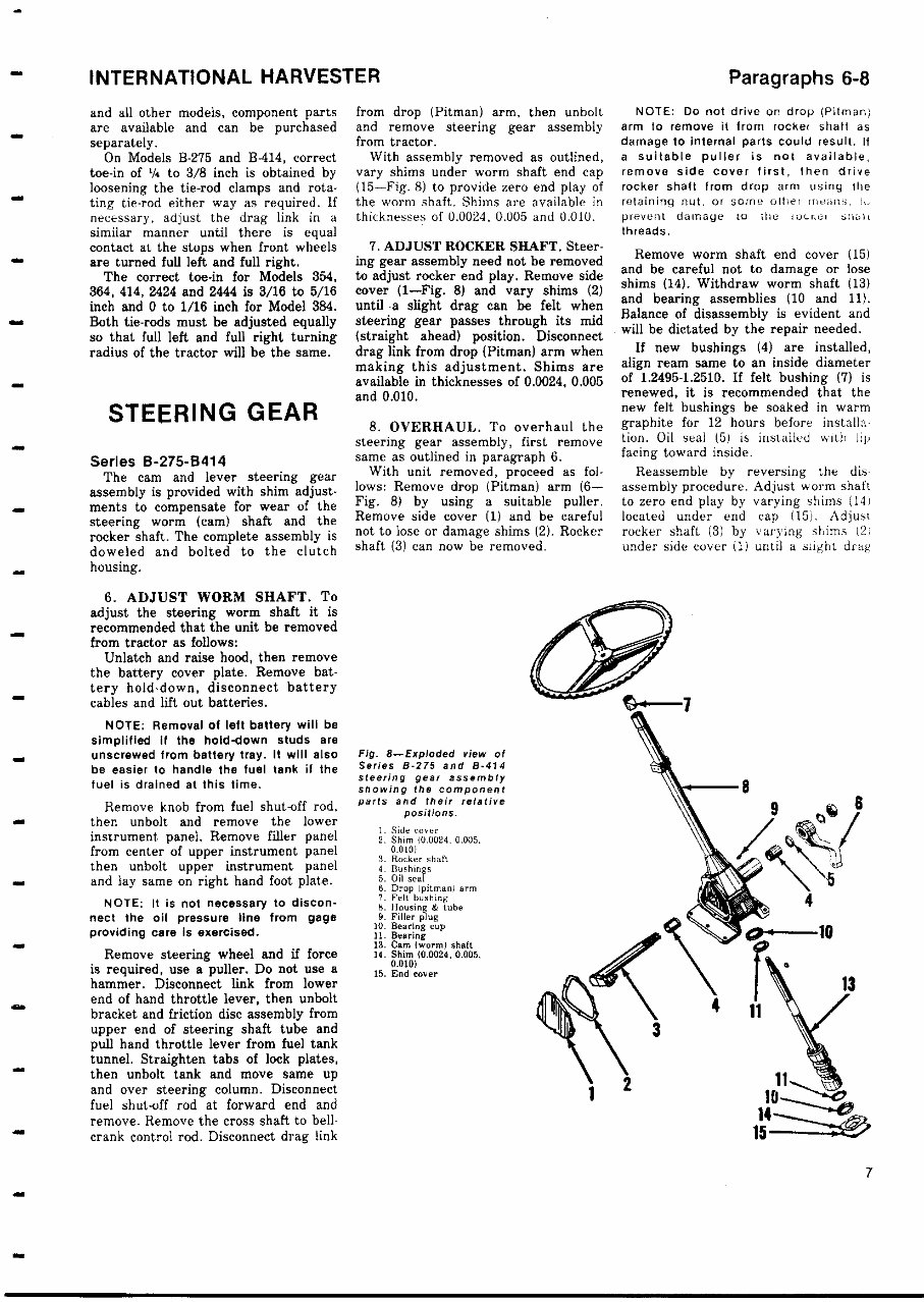
INTERNATIONAL HARVESTER and all other models, component parts are available and can be purchased separately. On Models B-275 and B-414, correct toe-in of 1/4 to 3/8 inch is obtained by loosening the tie-rod clamps and rota- ting tie-rod either way as required. If necessary, adjust the drag link in a similar manner until there is equal contact at the stops when front wheels are turned full left and full right. The correct toe-in for Models 354, 364, 414 , 2424 and 2444 is 3/16 to 5/16 inch and 0 to 1/16 inch for Model 384. Both tie - rods must be adjusted equally so that full left and full right turning radius of the tractor will be the same. from drop (Pitman) arm, then unbolt and remove steering gear assembly from tractor. With assembly removed as outlined, vary shims under worm shaft end cap (15-Fig. 8) to provide zero end play of the worm shaft. Shims are available in thicknesses of 0.0024, 0.005 and 0.010. 7. ADJUST ROCKER SHAFT. Steer- ing gear assembly need not be removed to adjust rocker end play. Remove side cover (1-Fig. 8) and vary shims (2) until -a slight drag can be felt when steering gear passes through its mid (straight ahead) position. Disconnect drag link from drop (Pitman) arm when making this adjustment. Shims are available in thicknesses of 0.0024, 0.005 and 0.010. STEERING GEAR Series B-275-8414 The cam and lever steering gear assembly is provided with shim adjust- ments to compensate for wear of the steering worm (cam) shaft and the rocker shaft. The complete assembly is doweled and bolted to the clutch housing. 6. ADJUST WORM SHAFT. To adjust the steering worm shaft it is recommended that the unit be removed from tractor as follows: Unlatch and raise hood, then remove the battery cover plate. Remove bat- tery hold-down, disconnect battery cables and lift out batteries. NOTE: Removal of left battery will be simplified if the hold-down studs are unscrewed from battery tray. It will also be easier to handle the fuel tank if the fuel is drained at this time. Remove knob from fuel shut-off rod, then unbolt and remove the lower instrument panel. Remove filler panel from center of upper instrument panel then unbolt upper instrument panel and lay same on right hand foot plate. NOTE : It is not necessary to discon- nect the oil pressure line from gage providing care is exercised. Remove steering wheel and if force is required, use a puller. Do not use a hammer. Disconnect link from lower end of hand throttle lever, then unbolt bracket and friction disc assembly from upper end of steering shaft tube and pull hand throttle lever from fuel tank tunnel. Straighten tabs of lock plates, then unbolt tank and move same up and over steering column. Disconnect fuel shut-off rod at forward end and remove. Remove the cross shaft to bell- crank control rod. Disconnect drag link 8. OVERHAUL. To overhaul the steering gear assembly, first remove same as outlined in paragraph 6. With unit removed, proceed as fol- lows: Remove drop (Pitman) arm (6- Fig. 8) by using a suitable puller. Remove side cover (1) and be careful not to lose or damage shims (2). Rocker shaft (3) can now be removed. Fig. 8-Exploded view of Series B - 275 and B-414 steering gear assembly showing the component parts and their relative positions. ). Side cover 2. Shim 10.0024. 0.005. 0.010) 3. Rocker shaft 4. Bushings 5. Oil seal 6. Drop Ipitman) arm 7. Felt bushing 6. Housing & tube 9. Filler plug 10. Bearing cup 11. Bearing 1s. Cam ( worm) shaft 14. Shim (0.0024 . 0.005. 0.010) 15. End cover Paragraphs 6-8 NOTE: Do not drive on drop (Pitman) arm to remove it from rocker shaft as damage to internal parts could result. If a suitable puller is not available, remove side cover first, then drive rocker shaft from drop arm using the retaining nut, or some other means .,. prevent damage to ille rocnei snot, threads. Remove worm shaft end cover (15) and be careful not to damage or lose shims (14). Withdraw worm shaft (13) and bearing assemblies (10 and 11). Balance of disassembly is evident and will be dictated by the repair needed. If new bushings (4) are installed, align ream same to an inside diameter of 1.2495-1.2510. If felt bushing (7) is renewed, it is recommended that the new felt bushings be soaked in warm graphite for 12 hours before installa- tion. Oil seal (5) is installed with Ill, facing toward inside. Reassemble by reversing the dis- assembly procedure. Adjust worm shaft to zero end play by varying shims (141 located under end cap (15). Adjust rocker shaft (3) by varying shims (2I under side cover (1) until a slight drug 11 14 5 7
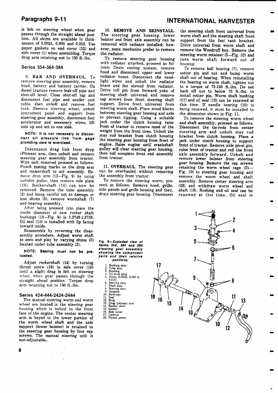
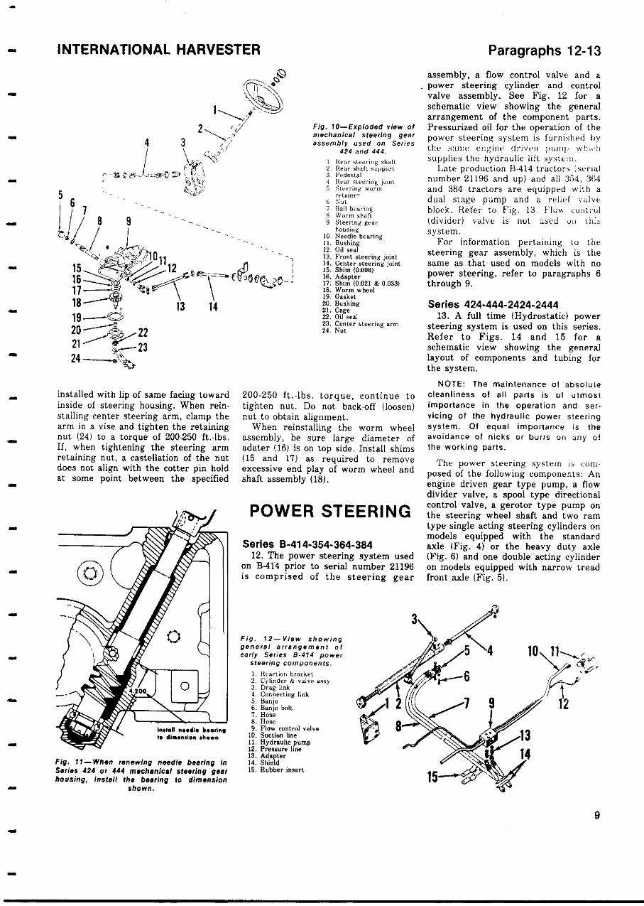
Paragraphs 9-11 is felt on steering wheel when gear passes through the straight ahead posi- tion. All shims are available in thick- nesses of 0.0024, 0.005 and 0.010. Use paper gaskets on end cover (15) and side cover (1) when assembling. Torque drop arm retaining nut to 150 ft. lbs. Series 354 - 364-384 9. R&R AND OVERHAUL. To remove steering gear assembly, remove hood, battery and battery carrier. On diesel tractors remove leak-off pipe and shut-off lever. Close shut-off tap and disconnect fuel pipe and sender unit cable, then unbolt and remove fuel tank. Remove steering wheel, unbolt instrument panel and support from steering gear assembly, disconnect foot accelerator and necessary wires, lift unit up and set to one side. NOTE : It is not necessary to discon- nect oil pressure line from gage providing care Is exercised. Disconnect drag link from drop (Pitman) arm, then unbolt and remove steering gear assembly from tractor. With unit removed proceed as follows: Punch mating marks on the drop arm and rockershaft to aid assembly. Re- move drop arm (13-Fig. 9) by using suitable puller, then remove side plate (16). Rockershaft (14) can now be removed. Remove the tube assembly (2) and being careful not to damage or lose shims (5). remove wormshaft (7) and bearing assembly. After being pressed into place the inside diameter of new rocker shaft bushings (10-Fig. 9) is 1 .3748-1.3758. Oil seal (11) is installed with lip facing toward inside. Reassemble by reversing the disas- sembly procedure. Adjust worm shaft to zero end play by varying shims (5) located under tube assembly (2). NOTE : Bearing must not be pre- loaded. Adjust rockershaft (14) by turning thrust screw ( 18) in side cover (16) until a slight drag is felt on steering wheel when gear passes through the straight ahead position. Torque drop arm retaining nut to 150 ft.-lbs. Series 424-444-2424-2444 The manual steering worm and worm wheel are located in the steering gear housing which is bolted to the front face of the engine. The center steering arm is keyed to the lower portion of the worm wheel shaft and the axle support (lower bolster) is retained to the steering gear housing by four cap screws. The manual steering unit is non-adjustable., INTERNATIONAL HARVESTER 10. REMOVE AND REINSTALL. The steering gear housing, lower bolster and front axle assembly can be removed with radiator installed; how- ever, some mechanics prefer to remove the radiator. To remove steering gear housing with radiator attached, proceed as fol- lows: Drain cooling system, remove hood and disconnect upper and lower radiator hoses. Disconnect the head- light wires and unbolt the radiator brace and fan shroud from radiator. Drive roll pin from forward yoke of steering shaft universal and remove cap screws from front steering, shaft support. Drive front universal from steering worm shaft. Place wood blocks between steering gear housing and axle to prevent tipping. Using a suitable jack under the clutch housing raise front of tractor to remove most of the weight from the front tires. Unbolt the stay rod bracket from clutch housing the steering gear housing from front of engine . Raise engine until crankshaft pulley will clear steering gear housing, then roll complete front end assembly from tractor. 11. OVERHAUL. The steering gear can be overhauled without removing the assembly from tractor. To remove the steering worm, pro- ceed as follows: Remove hood, grille, side panels and grille housing and then, drain steering gear housing. Disconnect Fig. 9-Exploded view of Series 354 , 364 and 384 steering gear assembly showing the component parts and their relative positions. 1. Bushing assy. 2. Tube any. 3. Bushing 4. Oil level plug 5. Shims (0.0024. 0.m5 & 0.010) 6. Bearing any. 7. Shaft easy. 8. Bearing any. 9. Housing 10. Bushings it. Seal 12. Ring i 3. Drop ( pitman) arm 4. Rocker shaft 15. Gasket 16. Side cover 17. Lockout 18. Thrust screw the steering shaft front universal from worm shaft and the steering shaft front support from the fuel tank bracket. Drive universal from worm shaft and remove the Woodruff key. Remove the steering worm retainer ( 5-Fig . 10) and turn worm shaft forward out of housing. To remove ball bearing (7), remove cotter pin and nut and bump worm shaft out of bearing. When reinstalling the bearing on worm shaft, tighten nut to a torque of 75-120 ft.-lbs. Do not back off nut to below 75 ft.lbs. to install cotter pin . Worm shaft bushing (11) and oil seal (12) can be renewed at this time. If needle bearing (10) is being renewed, it must be installed to the dimension shown in Fig. 11. To remove the steering worm wheel and shaft assembly, proceed as follows: Disconnect the tie - rods from center steering arm and unbolt stay rod bracket from clutch housing . Place a jack under clutch housing to support front of tractor . Remove axle pivot pin, raise front of tractor and roll the front axle assembly forward . Unbolt and remove lower bolster from steering gear housing . Remove the cap screws retaining the worm wheel cage (21- Fig. 10) to steering gear housing and remove the worm wheel and shaft assembly. Remove center steering arm (23) and withdraw worm wheel and shaft ( 18). Bushing and oil seal can be renewed at this time . Oil seal is a S als 8
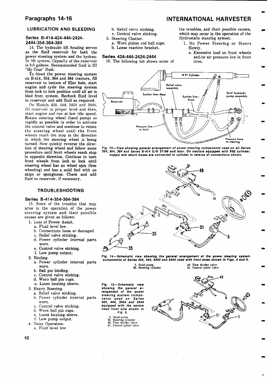
INTERNATIONAL HARVESTER installed with lip of same facing toward inside of steering housing. When rein- stalling center steering arm, clamp the arm in a vise and tighten the retaining nut (24) to a torque of 200-250 ft.-lbs. If, when tightening the steering arm retaining nut, a castellation of the nut does not align with the cotter pin hold at some point between the specified install nudlo bearing to dimension 'hean Fig. 11-When renewing needle bearing in Series 424 or 444 mechanical steering gear housing, install the bearing to dimension shown. Fig. 10-Exploded view of mechanical steering gear assembly used on Series 424 and 444. 1 near steering shah 2. near shaft support 3. Pedestal 4 Rear steering ialnt Steering worm retainer 6 Not 7. Ball hearing 8. Worn, shaft 9 Steering gear housing 10. Needle bearing i I. Bushing 2. Oil seal N . Front steering joint . Center steering joint 15. Shim (0.008) 6. Adapter i7: Shim ( 0.021 is 0d33) 18. Worm wheel 19. Gasket 20. Bushing 21. Cage 22. Oil meal 23. Center steering a rm 24. Not 200-250 ft.-tbs. torque, continue to tighten nut. Do not backoff (loosen) nut to obtain alignment. When reinstalling the worm wheel assembly, be sure large diameter of adater (16) is on top side. Install shims (15 and 17) as required to remove excessive end play of worm wheel and shaft assembly (18). POWER STEERING Series B-414 - 354-364-384 12. The power steering system used on B-414 prior to serial number 21196 is comprised of the steering gear Fig. 12 - View showing general arrangement of early Series B - 474 power steering components. 1. Reaction bracket 2 Cylinder & valve assy- 3. Drag link 4. Connecting link 5. Banjo 6. Banjo bolt 7. Hose S. Hos 9. Flow control valve 10. Suction line 11. Hydraulic pump 12. Pressure line 13. Adapter 14. Shield 15. Rubber insert Paragraphs 12-13 assembly, a flow control valve and a . power steering cylinder and control valve assembly . See Fig. 12 for a schematic view showing the general arrangement of the component parts. Pressurized oil for the operation of the power steering system is furnished by titer smile engine driven pump ,vh„ll supplies the hydraulic lilt system. Late production B-414 tractors (serial number 21196 and up ) and all 354, 364 and 384 tractors are equipped with a dual stage pump and a relief vulva block. Refer to Fig. 13. Flow convol (divider) valve is not used on tLa system. For information pertaining to the steering gear assembly , which is the same as that used on models with no power steering , refer to paragraphs 6 through 9. Series 424-444 - 2424-2444 13. A full time (Hydrostatic) power steering system is used on this series. Refer to Figs. 14 and 15 for a schematic view showing the general layout of components and tubing for the system. NOTE: The maintenance of absolute cleanliness of all parts is of utmost importance in the operation and ser. vicing of the hydraulic power steering system . Of equal importance is the avoidance of nicks or burrs on any of the working parts. The power steering system is com- posed of the following components: An engine driven gear type pump, a flow divider valve, a spool type directional control valve, a gerotor type pump on the steering wheel shaft and two ram type single acting steering cylinders on models equipped with the standard axle (Fig. 4) or the heavy duty axle (Fig. 6) and one double acting cylinder on models equipped with narrow tread front axle (Fig. 5). 9
Paragraphs 14-16 LUBRICATION AND BLEEDING Series B-414 - 424-444-2424- 2444 - 354-364-384 14. The hydraulic lift housing serves as the fluid reservoir for both the power steering system and the hydrau- lic lift system. Capacity of the reservoir is 3.0 gallons. Recommended fluid is IH "Hy-Tran" fluid. To bleed the power steering system on B-414, 354, 364 and 384 tractors, fill reservoir to bottom of filler hole, start engine and cycle the steering system from lock to lock position until all air is bled from system. Recheck fluid level in reservoir and add fluid as required. On Models 424, 444, 2424 and 2444, fill reservoir to proper level and then, start engine and run at low idle speed. Rotate steering wheel (hand pump) as rapidly as possible in order to activate the control valve and continue to rotate the steering wheel until the front wheels reach the stop in the direction in which the steering wheel is being turned. Now quickly reverse the direc- tion of steering wheel and follow same procedure until front wheels reach stop in opposite direction. Continue to turn front wheels from lock to lock until steering wheel has no wheel spin (free wheeling) and has a solid feel with no skips or sponginess. Check and add fluid to reservoir, if necessary. TROUBLESHOOTING Series B-414 . 354-364-384 15. Some of the troubles that may arise in the operation of the power steering system and their possible causes are given as follows: 1. Loss of Power Assist. a. Fluid level low. b. Connections loose or damaged. c. Relief valve sticking. d. Power cylinder internal parts worn. e. Control valve sticking. f. Low pump output. 2. Binding. a. Power cylinder internal parts worn. b. Ball pin binding. c. Control valve sticking. d. Worn ball pin cups. e. Loose locating sleeve. 3. Heavy Steering. a. Relief valve sticking. b. Power cylinder internal parts worn. c. Control valve sticking. d. Worn ball pin cups. e. Loose locating sleeve. f. Low pump output. 4. Noisy Operation. a. Fluid level low. INTERNATIONAL HARVESTER b. Relief valve sticking. c. Control valve sticking. 5. Steering Chatter. a. Worn piston rod ball cups. b. Loose reaction bracket. Series 424 - 444-2424-2444 16. The following list shows some of C the troubles, and their possible causes, which may occur in the operation of the Hydrostatic steering system. 1. No Power Steering or Steers Slowly. a. Excessive load on front wheels and/or air pressure low in front tires. R 91 Cylinder Relief valve as sembly 0 0 Suction line -Rear Reservoir Pressure line to hitch S Deal hydraulic pump asse mbly Pressure here to steering Fig. 13-View showing general arrangement of power steering components used on all Series 354, 364 , 384 and Series B-414 S/N 21196 and later . On tractors equipped with P92 cylinder, supply and return hoses are connected to cylinder In reverse of connections shown. 49 Fig. 14-Schematic view showing the general arrangement of the power steering system components of Series 424, 444, 2424 and 2444 used with front axles shown In Figs . 4 and 8. 5. Hand pump 49. Flow divider valve 85. Steering cylinder 51. Control (pilot) valve Fig. 15-Schematic view showing the general ar- rangement of the power a testing system compo- nents used on Series 424, 444, 2424 and 2444 equipped with the narrow tread front axle shown in Fig. S. 5. Hand pump 35. Steering cylinder 49. Flow divider valve 51. Control (pilot) valve w 10
This is the complete official full factory service repair manual for the IH International Harvester 2424 tractor. Whether you're a professional mechanic or a DIY enthusiast, this manual provides essential repair and service information for your IH International Harvester 2424 tractor. It includes detailed instructions for the general aspects, specifications, engine, cooling system, fuel system, power train, front axle, clutch, differential lock, electrical system, brakes, fenders, fuel tank & platform, final drive, front system, front-wheel drive, hydraulic system, main drive bevel gears and differential, park brake, power steering system, power take-off, rear axle, steering gear, transmission, and more.
With this manual, you can print out the specific pages you need or the entire manual. It features detailed substeps, notes, cautions, warnings, numbered instructions, bold figure numbers, illustrations, drawings, photos, enlarged insets, and a numbered table of contents for easy navigation. Additionally, it facilitates troubleshooting and electrical service procedures with detailed wiring diagrams. The manual comes in PDF format, compatible with all PC-based Windows operating systems and Mac, and can be saved to your hard drive or burned to CD-ROM. It's printable without any restrictions and requires Adobe Reader for access.
Get your IH International Harvester 2424 tractor service manual now to ensure your vehicle works properly and to save on costly repairs. The link for the manual will appear on the checkout page after payment is complete.
Recently Viewed
5,521,897Happy Clients
2,594,462eManuals
1,120,453Trusted Sellers
15Years in Business
Price:
Actual Price:
IH International Harvester 2424 Workshop Service Manual