

Lawn Tractor
Models 52072,52073 8 52074
Service Manual
PREPARING LAWN TRACTOR
FOR OPERATION
ASSEMBLY
CUSTOMER NOTICE! The engine on tRls lawn tractor
was shipped WITHOUT oli In tRe crankcase. See en-
glne Inrtndctlom for proper type oll and crankcase
capacity.
1. Cut the shipping carton open at all four (4) corners
and use as a working sufface. The battery, steering
wheel, ~ nd tractor seat are the only items that need
to be mounted on the tractor.
2. Empty the hardware bag. DO DQOT LOSE COHCENTS.
NOTE: See page 7 hardware illustration (drawn ac-
tual size for easy identification].
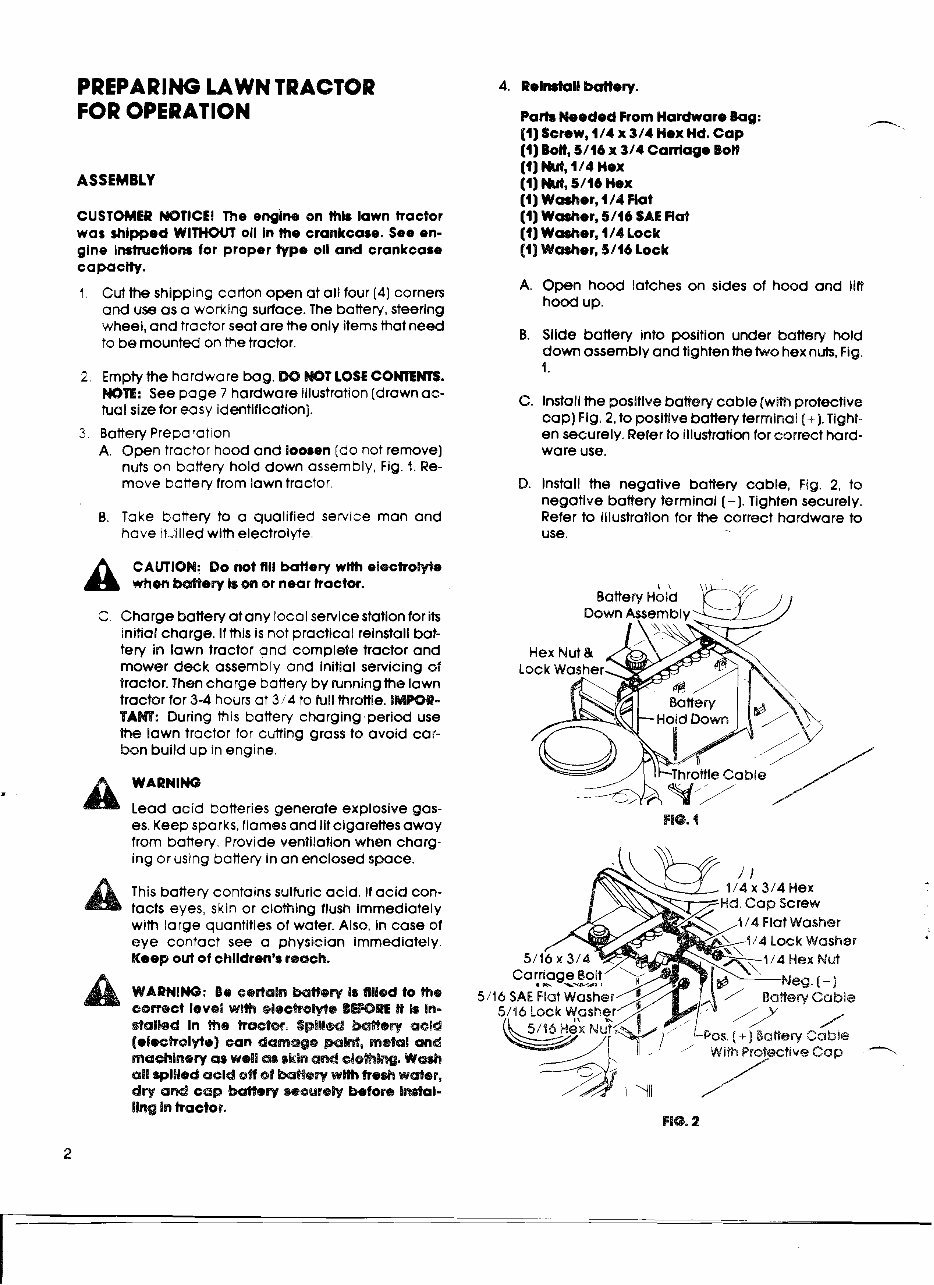
3. Battery Preparation
A. Open tractor hood and loosen (do not remove]
nuts on battery hold down assembly, Fig. i. Re-
move battery from lawn troctor.
8. Take bcttery to a qualified service man and
have it.iilledwith electrolyte.
A
CAMION: Do not flll batfey wlth elscProWe
when Meay Is of4 or near tractor.
C. Charge battery atany local servicestationfor its
initial charge. If this is not practical reinstall bat-
tery in lawn tractor and complete tractor and
mower deck assembly and initial servicing sf
tractor.Then charge battery by runningthe lawn
tractor for 3-4 hours at 3!4 to full throttle. DMmR-
TAW: During this battery charging.period use
the lawn tractor for cutting grass to avoid car-
bon build up in engine.
I
A wAmlNG Lead acid batteries generate explosive gas-
es. Keep sparks, flames and lit cigarettes away
from battery. Provide ventilation when charg-
ing or using battery in an enclosed space.
a
This battery contains sulfuric acid. If acid con-
tacts eyes, skin or clothing flush immediately
with large quantities of water. Also, in case of
eye contact see a physician immediately.
Keep out of children's reach.
WARNING: Be cerdaiss ht8@~ Is filed to the
derlkd In if19 Recctos. Spill& esld
(ei=%r@lytc] san damage mM, metal me$
rneehinesy es wdEi as skim ad elsmlw. Wash
all apllied acid off of Mew wwlPh fresh wder,
dry ad cap Marry r@ause& Before InsVal-
ling hn backs.
Darh Needed From Hardware Bag:
11) Screw, 1/4 x 3/4 Hex Hd. Cap
:1) ron, 5/16 x 314 Caniage BOB
:l) W, 114 Hex
:1) W, 5/16 Hex
:1)Washer, 1/4 Hat
:1)Washer, 5/16 SAL Rat
:1)Washer, 1/4 Lock
11) Washer, 5/16 Lock
A. Open hood latches on sides of hood and lift
hood up.
B. Slide battery into position under battery hold
down assembly and tighten the two hex nuts, Fig.
I.
C. Install the positive battery cable (withprotective
cap) Fig. 2, to positive battery terminal (+I. Tight-
en securely. Refer to illustration for correct hard-
ware use.
D. Install the negative battery cable, Fig. 2, to
negative battery terminal (-1. Tighten securely.
Refer to illustration for the correct hardware to
use.
.
Down ~ i s e m b l j
Hex Nut &
Lock Washer,
Battery
a C Hold Down 1
4 Flat Washer
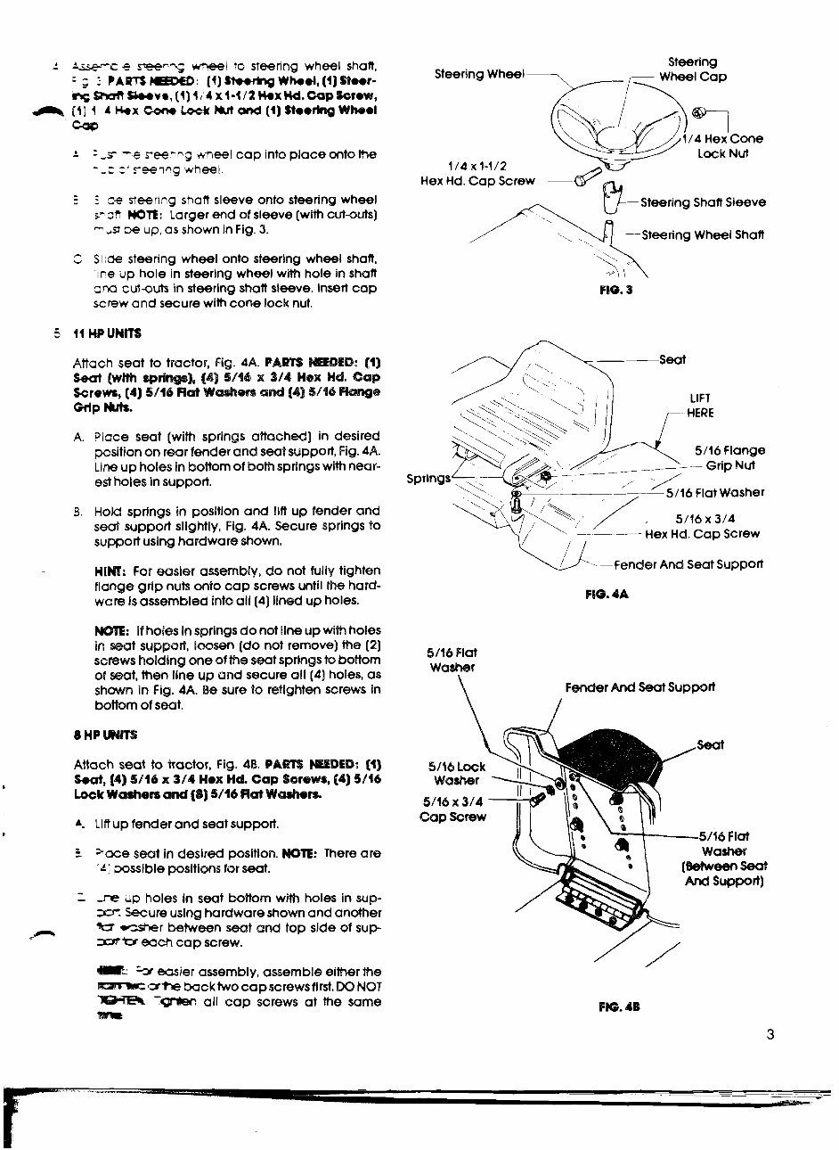
.: ke-c e s-eer-~ w-I to steenng wheel shaft,
= ; 2 PARTS : (1) Wwdng Whed, (1) Steer-
ng~~va,(l)1:'4xl-l/2H.xM.~p~rew,
a Id] 1 4 H x Corn Lo-& M ond (1) $teem Wheel
Cop
. -
- - ,s -e reelng meel cap into place onto lhe
- ,r: z' reevg wheel.
5 S c-e steerlng shalt sleeve onto steering wheel
cmsh WIE: Larger end of sleeve (with cut-outs)
-- ,s =>e up, as shown in Fig. 3.
C SIC%? steering wheel onto steering wheel shaft,
~~ne up hole in steering wheel with hole in shaft
ond cut-outs in steering shaft sleeve. lnsert cap
screw and secure with cone lock nut.
Attach seat to tractor, Fig. 4A. CAm mDED: [I]
Seat [with -rim), (49 5/66 x 3/41 Hex Hd. Cap
Screws, (4) 5/16 Rat Wdem and (4) 5/46 bslgs
Giip Ms.
k Place seat (with springs attached) in desired
positionon rgar fender and seat support, Fig. 4A.
Line up holes in bottomof bothsprings with near-
est holes in support.
B, Hold springs in position and lilt up fender and
seat suppod slightly, Fig. 4A. Secure springs to
support using hardware shown.
HIM: For easler assembly, do not fully tighten
flange grip nuts onto cap screws until h e hard-
wars is assembled into all (4) lined up holes.
: If holes Insprings do not lineup with holes
in seat support, iwsen [do not remove) the (2)
scmws holdlng one of the seat springs to bobtom
of seat, then line up and secure ail (4) holes, as
shown in Fig. 4A. Be sure to retighten screws in
bottom of seat.
Steering
Steering Wheel -
Steering Shaft Sleeve
/ ' w - S t e e r i n g Wheel Shaft
Sprlngs
5/16 Flat Washer
Hex Hd.Cap Screw
- -Fender And Seat Support
FIG. 4A
5/16 Flat
washer
Fender And Seat Support
/
8 HP M S
Attach seat to tractor, Fig. 48. PARTS WDED: (1)
Seat, [a) 3/16 x 3/41 Hex Hd. ,441) 5/46
.
Lock Washen and [Q) 5/16 R
A. Lift up fender and seat support.
P
I =ace seat in desired position. NOE: There are
d+ wssible posltions for seat.
I -re LIP holes in seat bottom with holes in sup-
-- Secure uslng hardwareshownand another
AW -=r between seat and top side of sup-
? -* $QC~ cap screw.
1: -3 easier assembly, assemble either me
amrmc she backtwo capscrewsflrst. BQ NOT
'm all cap screws at the same
-
Handle
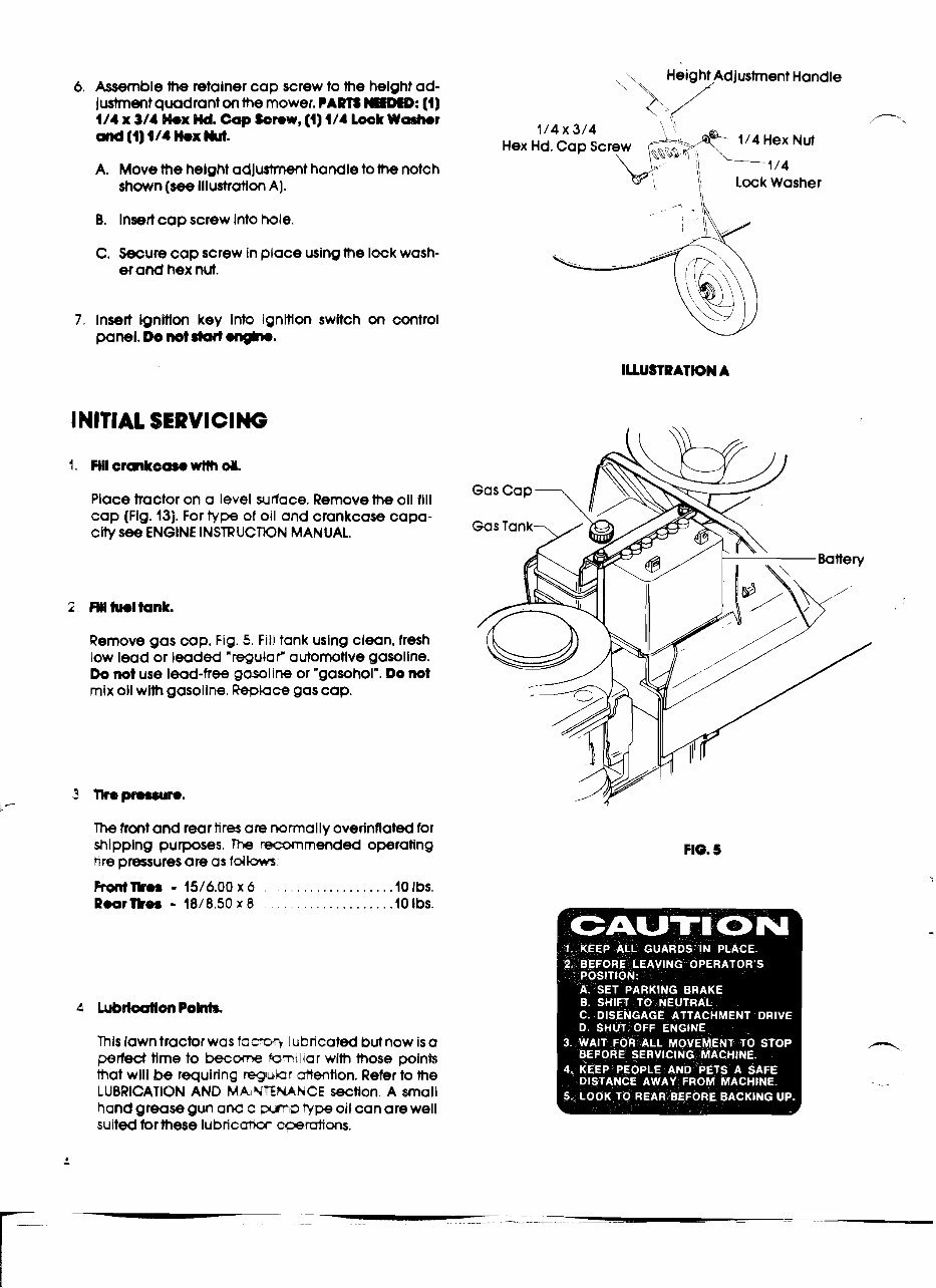
6. Assemble the retalner cap screw to the height ad-
Iwtmentquadrant on the mower. CARTS MEW: (1)
1/4 x 3/4 hx Wd. Cap %crow, (1) 1/4 Lock Wdb@r F-.
mBd (4) 414 kx M.
1/4 x 3/4
Hex Hd.Cap Screw
A. Move the helght adjushmmt handle to the notch
shown (see Illustration A].
B. Insertcop screw into hole.
C. Secure cap screw in place usingthe lock wash-
er and hex nut.
7, Insert ignltlon key Info ignmon swltch on control
panel. Do not start .ngh..
INITIAL SERVICING . s
Place tractor on a level surface. Removethe oil fill
cap (Fig. 13). For type of oil and crankcase capa-
city see ENGINE INSTRUCTtONMANUAL.
Remove gas cap, Fig. 5. Fill tank using clean, fresh
low lead or leaded 'regular' autornotlve gasoline.
Do not use lead-free gasoline or "gasohol". Do not
mix oil with gasoline. Replace gas cap.
The front and rear tires am normally overinflated for
shlpping purposes. The m m e n d e d operating
tire pressures are as tdb
This lawntractor was facto? lubricated but now is a
perfect time to becm kmtl~ar with those points
that wlll be requiring rqumr -tion. Refer to the
LUBRICATION AND MAINTENANCE section. A small
hand grease gun and a w p type oil can are well
sulted forthese lubncai-w meruiions.
CAW H TRACTOR CONI'ROLS
,-
Be wre ye~ read thb sectlon of the Qwnar's Wide
'>em you aWempt to operate your lawn tractor. It k
ror your safety that you know where all controb are
and are kmlllar wHh the tunctlonr of each control.
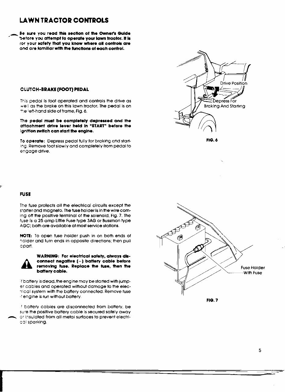
CLUTCH-BRAKE (FOOT) PEDAL
Tnls pedal is foot operated and controls the drive as
well as the brake on this lawn tractor. The pedal is on
i+>e left-handside of frame, Fig. 6.
The pedal must be completely depressed and me
attachment drlve lever held In "START" before me
lgnmon mHch can start the engine.
To operate: Depress pedal fully for braking and start-
,ng.Remove foot slowly and completely from pedal to
arlgage drive.
FUSE
FIG. 4
The fuse protects all the electrical circuits except the
starter and magneto. The fuse holder is in the wire com-
Ing off the positive terminal of the solenoid, Fig. 7. The
fuse is a 25 amp Llttle Fuse type 3AG or Bussmantype
AGC; both are available at most service statlons.
NOTE: To open fuse holder push in on both ends of
?older and turn ends in opposite directions;then pull
apart.
WARNING: For electrical safety, always dls-
A
cmnect negatlve I-) battery cable before
removing We. Replace the h e , then the
bdery cable.
If battery is dead, the engine may be started with jump-
er cables and operated without damage to the elec-
trical system with the battery connected. Remove fuse
if engine is run without battery.
FIG. 7
If battery cables are disconnected from battery, be
sure the positive battery cable is secured safely away
3r rnsulated from all metal surfaces to prevent electri-
cal sparking.
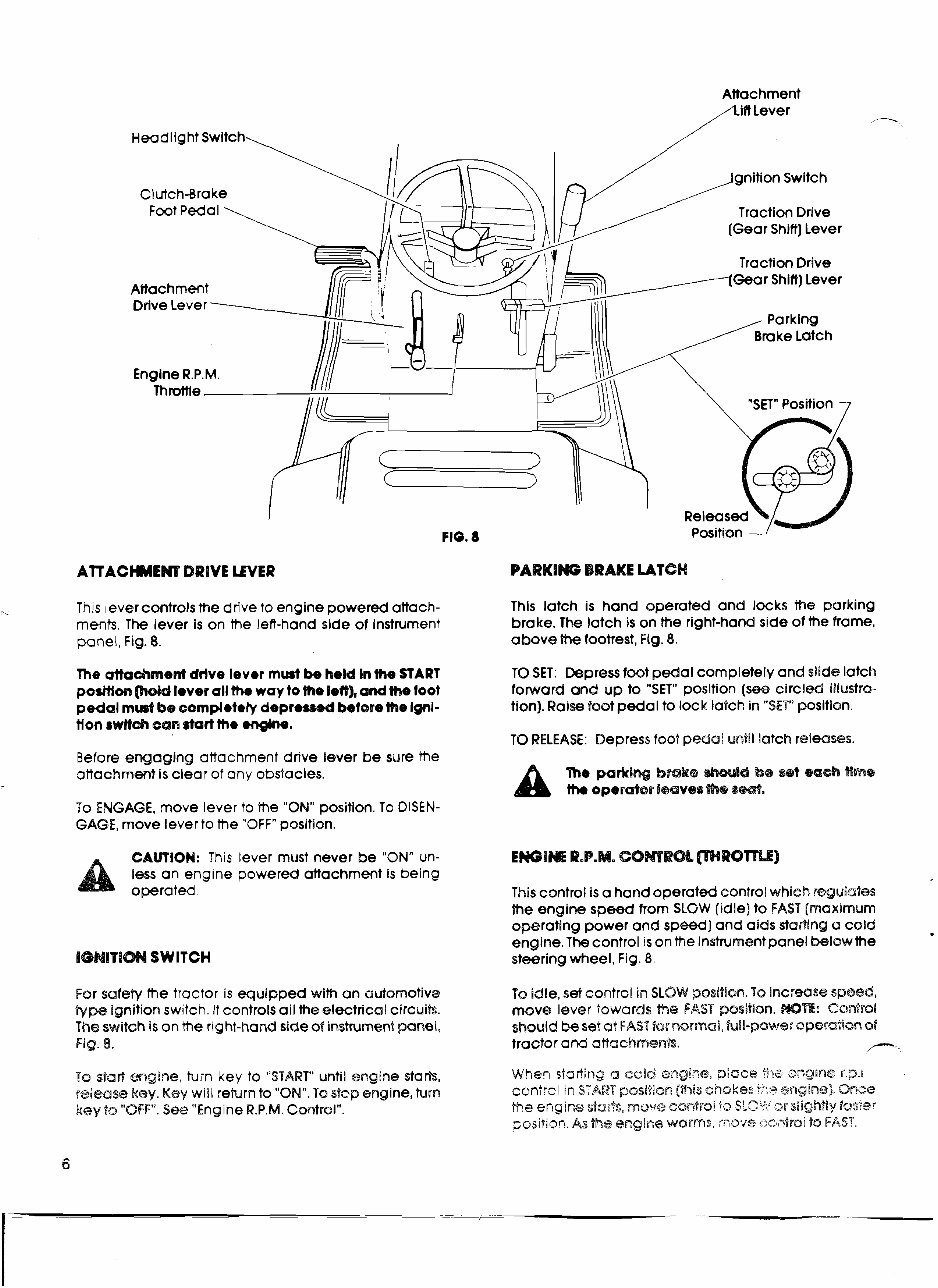
Attac hment
/ I i f i Lever
Headlight Switch
Traction Dr~ve
(Gear Shift] Lever
Traction Drive
Attachment
Gear Shift) Lever
-
-
AlTACHMENT DRIVE LEVER P A R K I W BRAKE LdTCH
?I
This lever controls the drive to engine powered attach- This latch is hand operated and locks me parking
ments. The lever is on the let?-hand side of instrument brake. The latch is on Wse right-hand side of the frame,
panel, Fig. 8. above the footrest, Fig. 8.
The attachment drive lever mud be held In me START TO SET: Dgpressfoot pedal completely and slide latch
pesttion Wld lever all th. way to me left), and me foot forward and up to "SET" position (see circled illustsa-
pedal mud be completdy depressed beforeme lgd- tion). Raise foot pedal to lock latch in "SET" position.
tlon sw11sR can start the engh.
TO RELEASE: Depress foot pedal until latch releases,
Before engaging attachment drive lever be sure the
attachment is clear of any obstacles.
a
The parking brake hu$d be s@t eaoh #me
lt~~ operder I@QV~S sM.
To ENGAGE, move lever to the "ON" position. To DISEN-
GAGE, move lever to the "OFF"position.
CALCalQN: This lever must never be "ON" un- EWlM @.P.M. COMPOL mROTT$$]
less an engine powered attachment is being
a owrat,.
This controi is a hand operated control which r@guiates
the engine speed from SLGW (idle)to FAST [maximum
operating power and speed] and aids starting a cold
engine. The control is on the instrumentpanel below the
%GBdlllTIM SWITCH steeringwheel, Fig. 8.
For safety the tractor is equipped with an automotive TQ idle, set contrci in SLOW position. To increase speed,
Bype ignition switch. It controls all the electrical circuits. move lever towards me FAST pssltion. WE: Control
The switch is on the nght-hand side of instrument pane?, should be set a? FAST Bsr normal, full-power operation of
Fig. 8. tractor am attachmew%. r"-
TO .ski!? mgine, tilin key to "START" until engine starts,
staeing a cold engirze, psiace l?-~e sngiiae r.p.6
rslmse key. Key will repurn to "ON". To stop engine, Pdrn
contr? ir! START psslOBon (ttais chokes i;?s sngln@;sE.Qnce
key $0 'OFF". SEE? "Engine R.P.M. ContsoIm.
5s engim ~f;:;cz&, mawe eantroi fa S ! ) : , ? ST ~jrgbtly f~s';~?
~~j~itiafi. angice warms, move coi-,tr~9 ta FAST,
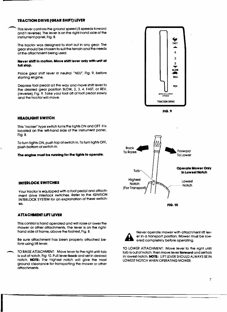
'- This lever controls the ground speed (5 speeds forward
and 1 reverse).The lever is on the right-handside of the
instrument panel, Fig. 8.
The tractor was designed to start out in any gear. The
gear should be chosento suit the terrain and the needs
of the attachment being used.
Mever rhMt In motlon. Move M Iever only wHh unR at
full stop.
Place gear shift lever in neutral "NEU", Fig. 9, before
starting engine.
Depress foot pedal all the way and move shift leverto
the desired gear position SLOW, 2, 3, 4, FAST, or REV.
(reverse], Fig. 9. Take your foot off of foot pedal slowly
and the tractor will move.
HEADLIGHT SWITCH
This "rocker type swltch turns the IightsONand OFF. It is
located on the left-hand side of the instrument panel,
Fig. 8.
To turn lights ON, push top of switch in.To turn lights OFF,
r
push bottom of switch in.
Tho ongh must be mlng tor the 1 - to operate.
INlERLOCK SWITCHES
Your tractor is equipped wlth a foot pedal and attach-
ment drive interlock swltches. Refer to the IGNITION
INTERLOCK SYSTEM for an explonatlon of these switch-
es.
AlTACHMENT LIFT LEVER
This control is hand operated and will raiseor lowerthe
mower or other attachments. The lever is on the right-
hand side of frame, above the footrest, Fig. 8.
Be sure attachment has been properly attached be-
fore using lift lever.
-, TO RAISEATTACHMENT: Move lever to the right untiltab
is out of notch, Fig. 10. Pull lever back and set in desired
notch. MOTE: The highest notch will give the most
ground clearance for transporting the mower or other
attachments.
b
FAST
A
4
3
2
v
SLOW
C)
HEU.
REV.
MOW IN SLOWER
SPEEDS
TRACTION DRIVE
Operate Mower Only
In Lowest Notch
Highest
Lowest
v Notch
FIG. 10
A
Never operate mower with attachment lift lev-
er in a transport position. Mower must be low-
ered completely before operating.
TO LOWER ATTACHMENT: Move lever to the right until
tab is out of notch;then move lever toward and set ta b
in lowest notch. NOTE: LIFT LEVER SHOULD ALWAYS BE IN
LOWEST NOTCH WHEN OPERATING MOWER.
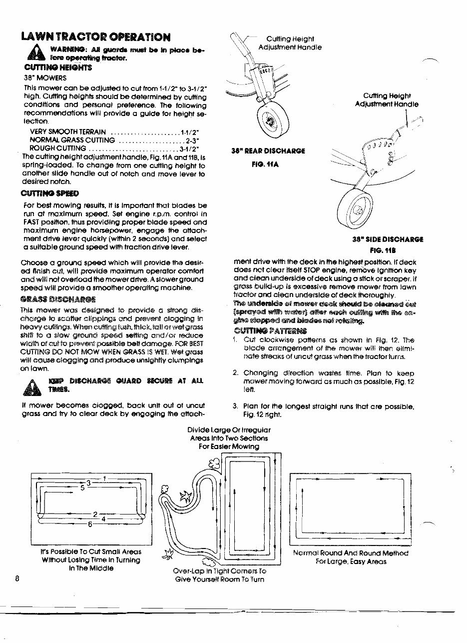
UW# BTBACTOR OPERATION Cutting Height
WARWOBW: U wrdo RsUPP h~ BW -0 b-
Adjustment an die
a, m*. /--.
38" MOWERS
This mower can be adjusted to cert from f-1/2" to 3-1/2"
high. Cutthg heights should tx determined by cutting
Cutting Helght
condMm and personal preference. The following
Adjustment Handle
rgcmmmdaWms will provide a guide for height se-
I~Won.
VERY S-TH TERRAIN .................... -1-1/2"
NORMAL GRASSCUTTING .2-3"
ROUGHGUTTING .......................... .3-112"
38" REAR DISCHARGE
...................
The cutting heightadjustmenthandle, Fig. 1iA and ilB, is
spring-loadd. To change from one cuttlng height to
FIG. 11A
another slide handle out of notch and move lever to
desired notch.
For best mowlng resulk, Lt is Important that blades be
run at mxlmum s . Set engine r.p.m. control In
FAST wsmm, thus providing proper blade and
maximum engine howpower, engage ach-
rptmt drive lever q (wHhln 2 swmds) and select
a suHable ground wlm tractlondrlve lever.
which will provide the deslr-
& flnlsh cut, will p maximum operator comfort
II not ovedmd h e mower drive. A slower ground
will provide a smwther opraMng machine.
This mowmr was deslgm $0 psovlda a @rmg die-
charge @ waW@r cl8pplmo and preermt clwglng In
hmv cmwgs. Whm els%ldng Bush. hick, bll or wetgras
shlW $0 a slow grwm s mMng and/or r&uce
wic%?~ of LC%% 8a pr@vmtr pslble bas0 damage. BEST
CURING NOT MOW WHEN MASS is WET. Wet grass
will eaw eiqglng and produce sighf fly clumping%
wi !awn.
mmt drive wlh the deck Inthe highest posmm. If deck
does not clear MI1 STOP engine, remkve ignmm key
and clmn undenide of deck using a &ck ar scraper. 01
gras buiM-up la excesive remove mower from lawn
trackr ad clean undenldie of d s k hroughly.
emw PA~RW
4. C& clockwise patterns as shown In Fig. 12. The
blade arrangement of the mokler will then allmi-
Rate sbwks sf uncbi grass when the tractor turns.
2. Changing direction wa&es time. Plan k keep
mower moving farnerd as much as possible, Fig. 92
!en.
If mower bscomes eloggd, back unit out of uncut 3. Plan for the longest straight runs that are possible,
grass and by to clear deck by engaging the attach- Fig. 12 rlght.
IYs P~~lble To Cut Small Areas
Wiihout LosingTime In Turning
InThe Middle
Divide Large Or Irregular
Areas Into Two W t i m s
For Easler Mowlng
Over-Lap In Tight Cornen To
8 Give ~6ursrsl<~wm TQ Turn
--- -
Normal RoundAnd Wound Wlebsd
For Large.Easy Arms
to desired position. Let foot pedal out slowly untll fully
engaged. Try all gear positions. Do not rhm In mom.
-
Save the close trimming for the end.
Sometimes it is easier to divide a large irregularly
shaped area into smaller sections, Fig. 12 center, to
keep the mower working more steadily or to keep
from reversing, turning or repeatingtoo often.
6 In a small area, where tight turns would cause lost
nme in the center if the normal round and round
methods were used,try the cutting method in Fig. 12
ieft. Make the second pass down the center of the
area rather than down the opposite side from the
first pass. This allows you to swing wide at the end of
each pass and still cut all the grass with a minimum
of reversing.
TRIAL RUN
how that you have located the controls and under-
star,d thelr operation and function It is tlme to test ride
your new tractor. Do this w~thout operating an attach-
mevt until you have the feel of the unit.
Rgmsmhs, Impreper we ef Wm beactor could
Beton r)aMw @actor be w e Ww gear &lP$ lever b ln
rleubl ''mm.
I, Move gear shift lever to neutral "NEU"
2 Move engine r.p.m. throttle to START If startlng a cold
engine. If starting a warm engine move control to
FAST.
3 30id attachment drive lever in START position.
4. Depresfoot pedal all the way down.
I. Turn ignitlon key to START until the engine starts. .
2. As the engine warms up move englne r.p.m.throffle
to FAST.
-:tart out in I'st gear (SLOW). TO CHANGE SPEED, depress
xt pedal all the way down and move gear shlft lever
1. Movegear shift lever to neutral "NEU".
2. Move attachment drive lever to OFF.
3. SET the parking brake.
TO STOP win
Turn ignition key to OFF. Remove key.
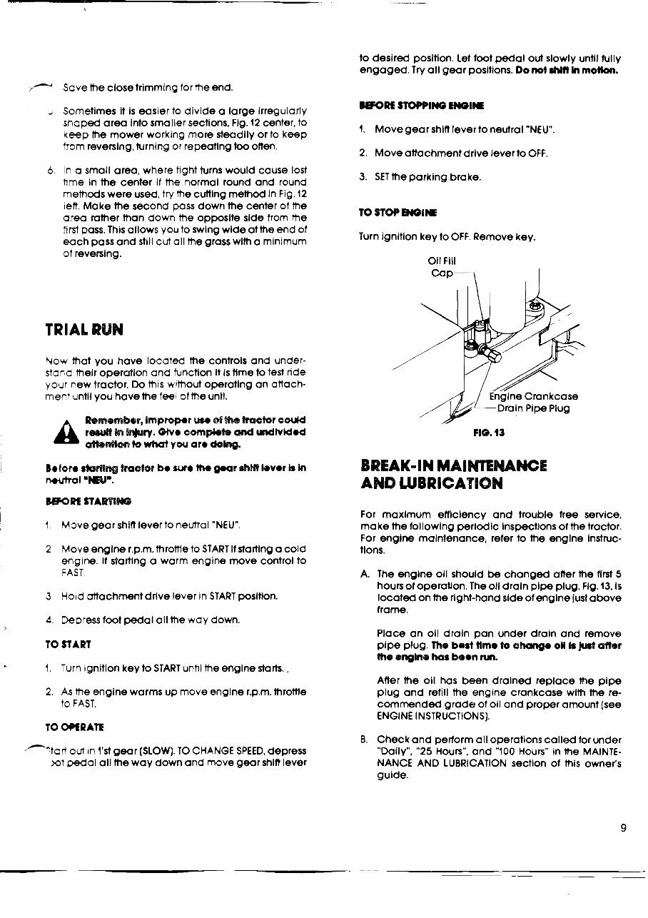
Oil Fill
I
e Crankcase
AND LUBRICATION
For maximum efficiency and trouble free service,
make the following periodic Inspecttons of the tractor.
For engine maintenance, refer to the engine instruc-
tlons.
A. The engine oil should be changed after the first 5
hours of operation. 'The oil draln pipe plug. Flg. 13, Is
located on the fight-hand slde of engine julabove
frame.
Place an oil drain pan under drain and remove
pipe plug. The b e d time to @Rang. o# k Jrsrt after
the englns hos been nn.
After the oil has been drained replace the pipe
plug and refill the engine crankcase with the re-
commended grade of oil and proper amount (see
ENGINE INSTRUCTIONS].
B. Check and perform all operationscalled for under
"Daily", "25 Hours", and "100 Hours" in the MAINTE-
NANCE AND LUBRICATION section of this owner's
guide.
MAIWENANCE AND LUBRICATION
DNY
Z4IERAL: Make general V I SA nspection of trac-
'+=r 'or loose or damaged m* Check nuts and
ccts periodically to rmre against looseness
:zLlsed by vibration or rougt- handling.Damaged
=c rh should be repaired or .eDtaced before using
-z ctor again.
E EUGINE OIL LEVEL: Refer r=: mgrne instructions.
Zneck oil level with tractor w ere1 ground and the
enginestopped Before mnng oil fill cap, clean
31rt from around oil fill o p e n n q
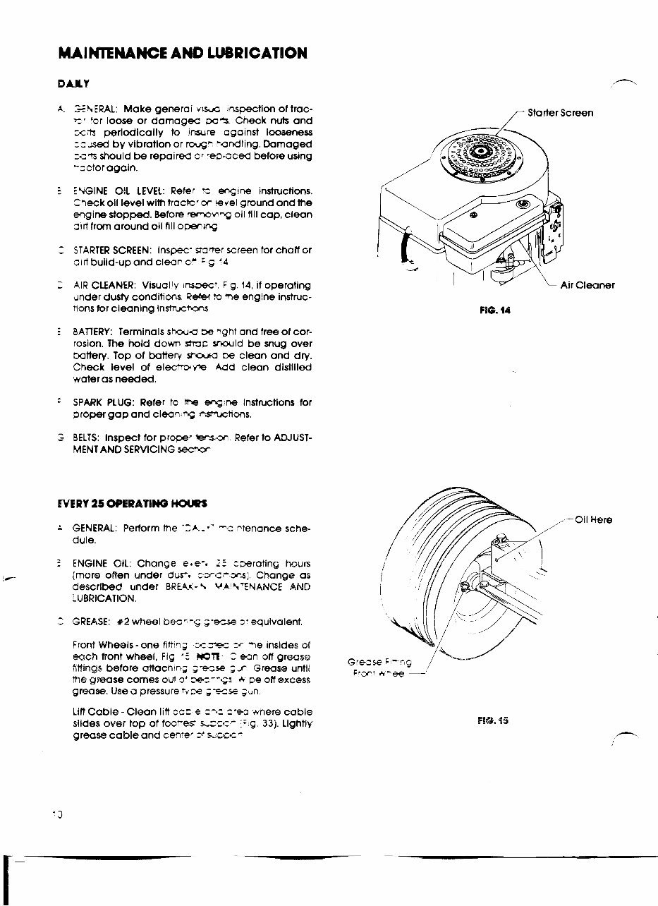
C STARTER SCREEN: Inspec- slr3-r screen tor chaff or
31rt build-upand clean 0 ' = c '4
2 AIRCLEANER: Visually ~nswc' Flg.14,ifoperating
under dusty conditions ReW to %e engine instruc-
nons for cleaning inshc*ors
E BAlTERY: Terminals s h Q be ~ght and free of cor-
rosion. The hold down stroo snould be snug over
mttery. Top of battery smd-~ clean and dry.
Check level of electmm8e Add clean distilled
water as needed.
:
SPARK PLUG: Refer to be wine instructions for
proper gap and c1ean.w nsmctions.
; BELTS: Inspect for props -icm Refer to ADJUST-
MENT AND SERVICING -
A GENERAL: Perform the -2A.-v-' --zntenancx? sche-
dule.
- -
3 ENGINE OIL: Change elecq L: =-rating hours
jms?@ often under dm, c~c-~ls] Change as
described under BREAK- % VA L.('EYANCE AND
L UBWICATIBN.
2 GREASE: #2 wheel bec---; ;--ie zr equivalent.
Front Wheels- one fittins 3zrpr zr me insides sf
each front wheel, Fig '5 WIT 2 eJn off grease
iiftings before aitachtn-,- ;-e=se ;s Grease until
the grease comes sui o' , = - -GI * w off excess
grmS9. Use a pressure 3 ze ;=ze jun
Lift Cable - Clean lift ca= e =-a= =-+a where cable
slides over top of footres LZ;C- = g 33). Lightly
grease cable and cen'ep =. ' sS.2tc-
r Starter Screen
-Oil Here
You're Reading a Preview
What's Included?
Fast Download Speeds
Online & Offline Access
Access PDF Contents & Bookmarks
Full Search Facility
Print one or all pages of your manual
$39.99
Gilson wards lawn tractor service maintenance manual
Viewed 93 Times Today

What's Included?
Fast Download Speeds
Online & Offline Access
Access PDF Contents & Bookmarks
Full Search Facility
Print one or all pages of your manual
$39.99

Secure transaction
What's Included?
Fast Download Speeds
Online & Offline Access
Access PDF Contents & Bookmarks
Full Search Facility
Print one or all pages of your manual
Description
A service maintenance manual for Gilson Wards compact tractors is available, covering models 52072, 52073, and 52074. This manual comprises 28 OEM pages of comprehensive information essential for the maintenance and repair of these tractors. It is a valuable resource for both professional mechanics and DIY enthusiasts.


