

FORDSON MAJOR Diesel Workshop Manual
What's Included?
Fast Download Speeds
Online & Offline Access
Access PDF Contents & Bookmarks
Full Search Facility
Print one or all pages of your manual
SHOP MANUAL
FORD
FORDSON DEXTA, FORDSON SUPER DEXTA
FORD 2 0 0 0 SUPER DEXTA
NEW PERFORMANCE SUPER DEXTA
Tractor serial number is stamped on ieft side of ciutch iiousing fiange and
prefixed by modei number. Engine seriai number is stamped on ieft hand
side of eyiinder block.
INDEX (By Starting Paragraph)
BELT PULLEY 82
BRAKES 77
CLUTCH
Adjustment 54
R&R and Overhaul 57
COOLING SYSTEM
Pump R&R and Overhaul 51
Radiator ] 5Q
DIESEL FUEL SYSTEM
Filters and Bleeding 35
Injection Pump 45
Nozzles ] ^ / 37
Trouble Shooting [[[[ 30
DIFFERENTIAL
Overhaul $7
Remove and Reinstall 66
ENGINE >. ;
Assembly R&R 9
Cam Followers ][ I3
Camshaft \[\ 20
Connecting Rod Bearings .*'..! 24
Crankshaft and Bearings [[[ 25
Crankshaft Oil Seals !!!!!!!! 26
Cylinder Head !.!.!!!!!! 10
Cylinder Sleeves .*,. 22
Flywheel R&R ...//.,.[./.., 27
Front Oil Seal !.!!!!.!!.!! 26
Main Bearings !,..!.!!!!!!!!! 25
Oil Pump ....,.//,./.]..,,[..[] 28
Pistons !.!!!!!!!!!!!!!! 22
Piston Pins !...!..!.!!!!!.!.!. 23
Piston and Hod Removal .* ........ !...! 21
Piston Rings , 22
Rear OU Seal ' ......... !.!.,.!.*!!!!..!,'.' 26
Rocker Arms [ ^ 14
Toppets ................. ! 13
Timing Gear Cover 15
Timing Gears ..././...[,.,...,...[ 16
Vaives and Seats ...[,....[.[.[. 11
Valve Guides & Springs ,..,,.....,.... 12
ELECTRICAL SYSTEM
Generator and Regulator. 52
Starting Motor !!!!!!!!!!.'! .53
FINAL DRIVE
Axle Housings 7g
Bevel Pinion 70
Bevel Ring Gear 67
Differential Lock ....... ! 68
Differential Overhaul .' 67
Wheel Ajde Shaft Bearing Adjustment .../...,. 74
Wheei Axle Shaft Bearings Renew 75
Wheel Axle Shaft R&H ;...*; 75
FRONT AXLE
Axle Main Member 2
Drag Links and Toe-in ,..[..[. 4
Front Support .../,.. 3
Steering Spindles /....[.[ 1
HYDRAULIC LIFT SYSTEM
Back Pressure Valve, R&R 100
Constant Draft Control, Adjustment 89
Control Valve, Overhaul 95 or 96
Cylinder and Piston, Overhaul 94
Implement, Bobbing * ] 85
Implement Position. Adjustment [,[. 90
Lift Cover, R&R ] ' 91
Pump. Overhaul !! 103
Pump, R&R 102
Relief Valve, R&R ^ IQI
Safety Valve R&R .'*.. 93
System Pressure Check 101
Valve Linkage, Checking 99
Work Cylinder, R&R ['//, 94
POWER TAKE-OFF
Countershaft $2
Input Shaft !!.!!.*. 59
Output Shaft ,[./....]. 79
Shifter Unit /,..../.[.[. 80
REAR AXLE
Bearing Adjustment 74
Shaft, R&R 75
STEERING GEAR
Adjustment g
Overhaul 8
Remove and Reinstall 7
TRANSMISSION
Assembly R&R , 60
Clutch Shaft !..!!! 59
Main Transmission 64
PTO Countershaft 62
Secondary Transmission 63
Shifter Rails and Forks 65
CONDENSED SERVICE DATA
GENERAL
Torque Recommendations See End of Shop Manual
Engine Make Perkins
Cylinders ^
Bore—Inches, Fordson Dexta 3.5
Bore-Inches, Fordson Super Dexta, Ford 2000 Super Dexta,
New Performance Super Dexta 3.6
Stroke —Inches ^
Displacement—Cubiclnches, Fordson Dexta 144
Displacement—Cubic Inches, Fordson Super Dexta,
Ford 2000 Super Dexta, New Performance Super Dexta 152.7
Compression Ratio (144 cu. in.) 16.5:1
(152.7 cu. in.) 17.4:1
Pistons Removed From: Above
Main & Rod Bearings Adjustable? No
Cylinder Sleeves—Type • • • l^^y
Generator & Starter Make Lucas
TUNE-UP
Firing Order 1-2-3
ValveTappetGap-lntake& Exhaust 0.01 OH
Valve Face Angle—Degrees 44
Valve Seat Angle—Degrees 45
Engine Low Idle-RPM 550
Engine High Idle-RPM (New Performance Super Dexta 2450
Engine High Idle-RPM (All Other Models) 2200
PTO High Idle-RPM See Paragraph 47 or 48
Battery Terminal Grounded Positive
SIZES-CAPACITIES-CLEARANCES
Crankshaft Journal Diameter 2.749
Crankpin Diameter 2.249
Camshaftjournals Diameter (Front) 1-87
(Center) 1-86
(Rear) 1-84
Piston Pin Diameter 1-25
Valve Stem Diameter, Intake 0.3115
Valve Stem Diameter, Exhaust 0.3115
Main Bearing Diametral Clearance 0.0025-0.0045
Rod Bearings Diametral Clearance 0.002-0.0035
PistonSkirtClearance(144cu. in. engine) 0.0035-0.0055
Piston Skirt Clearance (152 cu. in. engine) 0.0045-0.0065
Crankshaft End Play 0.002-0.010
Camshaft Bearing Diametral Clearance 0.004-0.008
Cooling System—Quarts 9
Crankcase—Quarts (with Filter) -8
Transmission—Quarts 14
Differential, Final Drive & Hydraulic Reservoir-Quarts 20.4
Steering Gear Housing 1 Pint
FRONT SYSTEM AND STEERING
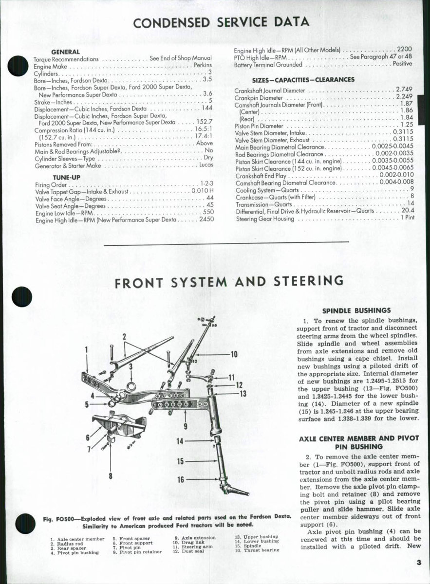
FO500—Exploded view »f front cale and reloted parts used on the Fordson Dexta.
' Similarity to American produced Ford tractors will be noted.
1. Axle center member
2. Radius rod
3. Rear spacer
4. Pivot pin bushing
5. Front spacer
6. Front support
7. Pivot pin
8. Pivot pin retainer
9. Axle extenaion
10. Drag link
11. Steering arm
12. Dust seal
13. Upper bushing
14. Lower bushing
15. Spindle
lC. Thrust bearing
SPINDLE BUSHINGS
1. To renew the spindle bushings,
support front of tractor and disconnect
steering arms from the wheel spindles.
Slide spindle and wheel assemblies
from axle extensions and remove old
bushings using a cape chisel. Install
new bushings using a piloted drift of
the appropriate size. Internal diameter
of new bushings are 1.2495-1.2515 for
the upper bushing (13—Fig. FO500)
and 1.3425-1.3445 for the lower bush-
ing (14). Diameter of a new spindle
(15) is 1.245-1.246 at the upper bearing
surface and 1.338-1.339 for the lower.
AXLE CENTER MEMBER AND PIVOT
PIN BUSHING
2. To remove the axle center mem-
ber (1—Fig. FO500), support front of
tractor and unbolt radius rods and axle
extensions from the axle center mem-
ber. Remove the axle pivot pin clamp-
ing bolt and retainer (8) and remove
the pivot pin using a pilot bearing
puller and slide hammer. Slide axle
center member sideways out of front
support (6).
Axle pivot pin bushing (4) can be
renewed at this time and should be
installed with a piloted drift. New
Paragraphs 3-6
FORD AND FORDSON
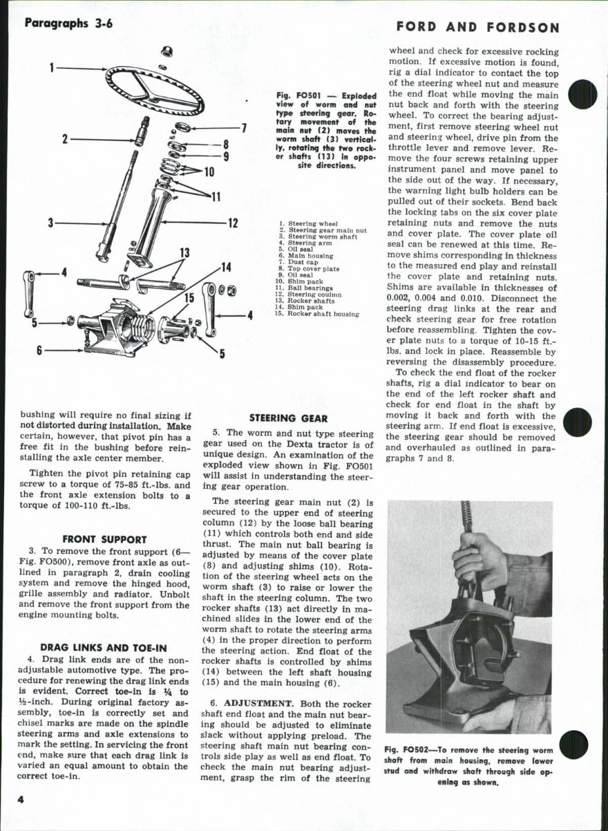
Fig. FO501 — Exploded
view of worm and nut
type steering gear. Ro-
tary movement of the
main nut (2) moves the
worm shaft (3) vertical-
ly, rotating the two rock-
er shafts (13) in oppo-
site directions.
1. steering wheel
2. Steering gear main nut
3. Steering worm shaft
4. Steering arm
5. on seal
6. Main housing
7. Dust cap
8. Top cover piate
9. Oil seai
10. Shim pack
11. Bali bearings
12. Steering coulmn
13. Rocker shafts
14. Shim pack
15. Rocker shaft housing
bushing will require no final sizing if
not distorted during installation. Make
certain, however, that pivot pin has a
free fit in the bushing before rein-
stalling the axle center member.
Tighten the pivot pin retaining cap
screw to a torque of 75-85 ft.-lbs. and
the front axle extension bolts to a
torque of 100-110 ft.-lbs.
FRONT SUPPORT
3. To remove the front support (6—
Fig. FO500), remove front axle as out-
lined in paragraph 2, drain cooling
system and remove the hinged hood,
grille assembly and radiator. Unbolt
and remove the front support from the
engine mounting bolts.
DRAG LINKS AND TOE-IN
4. Drag link ends are of the non-
adjustable automotive type. The pro-
cedure for renewing the drag link ends
is evident. Correct toe-in is % to
%-inch. During original factory as-
sembly, toe-in is correctly set and
chisel marks are made on the spindle
steering arms and axle extensions to
mark the setting. In servicing the front
end, make sure that each drag link is
varied an equal amount to obtain the
correct toe-in.
STEERING GEAR
5. The worm and nut type steering
gear used on the Dexta tractor is of
unique design. An examination of the
exploded view shown in Fig. FO501
will assist in understanding the steer-
ing gear operation.
The steering gear main nut (2) is
secured to the upper end of steering
column (12) by the loose ball bearing
(11) which controls both end and side
thrust. The main nut ball bearing is
adjusted by means of the cover plate
(8) and adjusting shims (10). Rota-
tion of the steering wheel acts on the
worm shaft (3) to raise or lower the
shaft in the steering column. The two
rocker shafts (13) act directly in ma-
chined slides in the lower end of the
worm shaft to rotate the steering arms
(4) in the proper direction to perform
the steering action. End float of the
rocker shafts is controlled by shims
(14) between the left shaft housing
(15) and the main housing (6).
6. ADJUSTMENT. Both the rocker
shaft end float and the main nut bear-
ing should be adjusted to eliminate
sJack without applying preload. The
steering shaft main nut bearing con-
trols side play as well as end float. To
check the main nut bearing adjust-
ment, grasp the rim of the steering
wheel and check for excessive rocking
motion. If excessive motion is found,
rig a dial indicator to contact the top
of the steering wheel nut and measure
the end float while moving the main
nut back and forth with the steering
wheel. To correct the bearing adjust-
ment, first remove steering wheel nut
and steering wheel, drive pin from the
throttle lever and remove lever. Re-
move the four screws retaining upper
instrument panel and move panel to
the side out of the way. If necessary,
the warning light bulb holders can be
pulled out of their sockets. Bend back
the locking tabs on the six cover plate
retaining nuts and remove the nuts
and cover plate. The cover plate oil
seal can be renewed at this time. Re-
move shims corresponding in thickness
to the measured end play and reinstall
the cover plate and retaining nuts.
Shims are available in thicknesses of
0.002, 0.004 and 0.010. Disconnect the
steering drag links at the rear and
check steering gear for free rotation
before reassembling. Tighten the cov-
er plate nuts to a torque of 10-15 ft.-
lbs. and lock in place. Reassemble by
reversing the disassembly procedure.
To check the end float of the rocker
shafts, rig a dial indicator to bear on
the end of the left rocker shaft and
check for end float in the shaft by
moving it back and forth with the
steering arm. If end float is excessive,
the steering gear should be removed
and overhauled as outlined in para-
graphs 7 and 8.
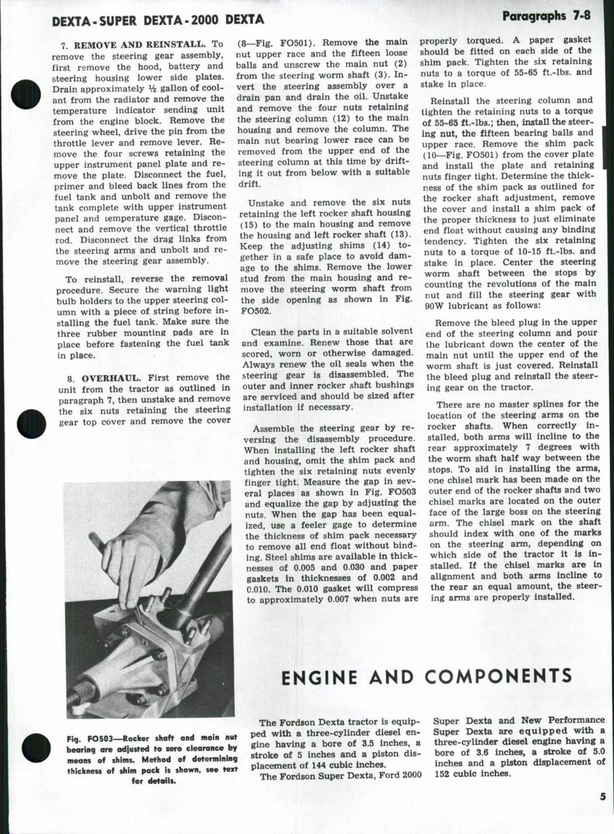
Fig. FO502—To remove the steering worm
shaft from main housing, remove lower
stud and withdraw shaft through side op-
ening as shown.
DEXTA-SUPER DEXTA-2000 DEXTA
Paragraphs 7-8
7. REMOVE AND REINSTALL. To
remove the steering gear assembly,
first remove the hood, battery and
steering housing lower side plates.
Drain approximately Vz gallon of cool-
ant from the radiator and remove the
temperature indicator sending unit
from the engine block. Remove the
steering wheel, drive the pin from the
throttle lever and remove lever. Re-
move the four screws retaining the
upper instrument panel plate and re-
move the plate. Disconnect the fuel,
primer and bleed back lines from the
fuel tank and unbolt and remove the
tank complete with upper instrument
panel and temperature gage. Discon-
nect and remove the vertical throttle
rod. Disconnect the drag links from
the steering arms and unbolt and re-
move the steering gear assembly.
To reinstall, reverse the removal
procedure. Secure the warning light
bulb holders to the upper steering col-
umn with a piece of string before in-
stalling the fuel tank. Make sure the
three rubber mounting pads are in
place before fastening the fuel tank
in place.
8. OVERHAUL. First remove the
unit from the tractor as outlined in
paragraph 7, then unstake and remove
the six nuts retaining the steering
gear top cover and remove the cover
(8—Fig. FO501). Remove the main
nut upper race and the fifteen loose
balls and unscrew the main nut (2)
from the steering worm shaft (3). In-
vert the steering assembly over a
drain pan and drain the oil. Unstake
and remove the four nuts retaining
the steering column (12) to the main
housing and remove the column. The
main nut bearing lower race can be
removed from the upper end of the
steering column at this time by drift-
ing it out from below with a suitable
drift.
Unstake and remove the six nuts
retaining the left rocker shaft housing
(15) to the main housing and remove
the housing and left rocker shaft (13).
Keep the adjusting shims (14) to-
gether in a safe place to avoid dam-
age to the shims. Remove the lower
stud from the main housing and re-
move the steering worm shaft from
the side opening as shown in Fig.
FO502.
Clean the parts in a suitable solvent
and examine. Renew those that are
scored, worn or otherwise damaged.
Always renew the oil seals when the
steering gear is disassembled. The
outer and inner rocker shaft bushings
are serviced and should be sized after
installation if necessary.
Assemble the steering gear by re-
versing the disassembly procedure.
When installing the left rocker shaft
and housing, omit the shim pack and
tighten the six retaining nuts evenly
finger tight. Measure the gap in sev-
eral places as shown in Fig. FO503
and equalize the gap by adjusting the
nuts. When the gap has been equal-
ized, use a feeler gage to determine
the thickness of shim pack necessary
to remove all end float without bind-
ing. Steel shims are available in thick-
nesses of 0.005 and 0.030 and paper
gaskets in thicknesses of 0.002 and
0.010. The 0.010 gasket will compress
to approximately 0.007 when nuts are
properly torqued. A paper gasket
should be fitted on each side of the
shim pack. Tighten the six retaining
nuts to a torque of 55-65 ft.-lbs. and
stake in place.
Reinstall the steering column and
tighten the retaining nuts to a torque
of 55-65 ft.-lbs.; then, install the steer-
ing nut, the fifteen bearing balls and
upper race. Remove the shim pack
(10—Fig. FO501) from the cover plate
and install the plate and retaining
nuts finger tight. Determine the thick-
ness of the shim pack as outlined for
the rocker shaft adjustment, remove
the cover and install a shim pack of
the proper thickness to just eliminate
end float without causing any binding
tendency. Tighten the six retaining
nuts to a torque of 10-15 ft.-lbs. and
stake in place. Center the steering
worm shaft between the stops by
counting the revolutions of the main
nut and fill the steering gear with
90W lubricant as follows:
Remove the bleed plug in the upper
end of the steering column and pour
the lubricant down the center of the
main nut until the upper end of the
worm shaft is just covered. Reinstall
the bleed plug and reinstall the steer-
ing gear on the tractor.
There are no master splines for the
location of the steering arms on the
rocker shafts. When correctly in-
stalled, both arms will incline to the
rear approximately 7 degrees with
the worm shaft half way between the
stops. To aid in installing the armg,
one chisel mark has been made on the
outer end of the rocker shafts and two
chisel marks are located on the outer
face of the large boss on the steering
arm. The chisel mark on the shaft
should index with one of the marks
on the steering arm, depending on
which side of the tractor it is in-
stalled. If the chisel marks are in
alignment and both arms incline to
the rear an equal amount, the steer-
ing arms are properly installed.
ENGINE AND COMPONENTS
Fig. FO503—Roeiier shaft and main nut
bearing are adjusted to zero clearance by
means of shims. Method of determining
thickness of shim pack is shown, see text
for details.
The Fordson Dexta tractor is equip-
ped with a three-cylinder diesel en-
gine having a bore of 3.5 inches, a
stroke of 5 inches and a piston dis-
placement of 144 cubic inches.
The Fordson Super Dexta, Ford 2000
Super Dexta and New Performance
Super Dexta are equipped with a
three-cylinder diesel engiie having a
bore of 3.6 inches, a stroke of 5.0
inches and a piston displacement of
152 cubic inches.
Paragraphs 9-11
FORD AND FORDSON
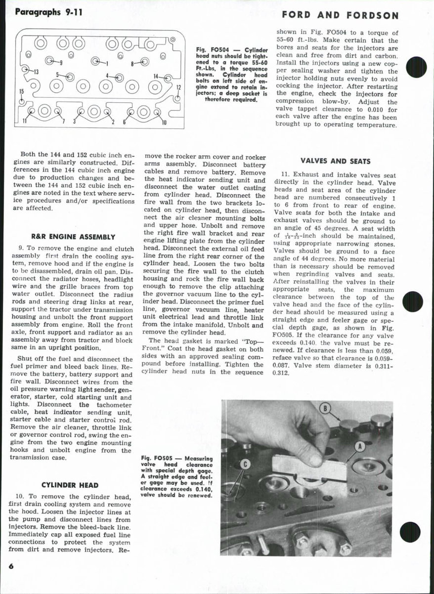
Fig. FO504 — Cyiinder
head nuts shouid be Hghf-
ened to a forque 55-60
Ff.-Lbs. in the sequence
shown. Cyiinder head
bolts on left side of en-
gine extend to retain in-
jectors; a deep socicet is
therefore required.
shewn in Fig. FO504 to a torque of
55-60 ft.-lbs. Make certain that the
bores and seats for the injectors are
clean and free from dirt and carbon.
Install the injectors using a new cop-
per sealing washer and tighten the
injector holding nuts evenly to avoid
cocking the injector. After restarting
the engine, check the injectors for
compression blow-by. Adjust the
valve tappet clearance to 0.010 for
each valve after the engine has been
brought up to operating temperature.
Both the 144 and 152 cubic inch en-
gines are similarly constructed. Dif-
ferences in the 144 cubic inch engine
due to production changes and be-
tween the 144 and 152 cubic inch en-
gines are noted in the text where serv-
ice procedures and/or specifications
are affected.
R&R ENGINE ASSEMBLY
9. To remove the engine and clutch
assembly first drain the cooling sys-
tem, remove hood and if the engine is
to be disassembled, drain oil pan. Dis-
connect the radiator hoses, headlight
wire and the grille braces from top
water outlet. Disconnect the radius
rods and steering drag links at rear,
support the tractor under transmission
housing and unbolt the front support
assembly from engine. Roll the front
axle, front support and radiator as an
assembly away from tractor and block
same in an upright position.
Shut off the fuel and disconnect the
fuel primer and bleed back lines. Re-
move the battery, battery support and
fire wall. Disconnect wires from the
oil pressure warning light sender, gen-
erator, starter, cold starting unit and
lights. Disconnect the tachometer
cable, heat indicator sending unit,
starter cable and starter control rod.
Remove the air cleaner, throttle link
or governor control rod, swing the en-
gine from the two engine mounting
hooks and unbolt engine from the
transmission case.
CYLINDER HEAD
10. To remove the cylinder head,
first drain cooling system and remove
the hood. Loosen the injector lines at
the pump and disconnect lines from
injectors. Remove the bleed-back line.
Immediately cap all exposed fuel line
connections to protect the system
from dirt and remove injectors. Re-
move the rocker arm cover and rocker
arms assembly. Disconnect battery
cables and remove battery. Remove
the heat indicator sending unit and
disconnect the water outlet casting
from cylinder head. Disconnect the
fire wall from the two brackets lo-
cated on cylinder head, then discon-
nect the air cleaner mounting bolts
and upper hose. Unbolt and remove
the right fire wall bracket and rear
engine lifting plate from the cylinder
head. Disconnect the external oil feed
line from the right rear corner of the
cylinder head. Loosen the two bolts
securing the fire wall to the clutch
housing and rock the fire wall back
enough to remove the clip attaching
the governor vacuum line to the cyl-
inder head. Disconnect the primer fuel
line, governor vacuum line, heater
unit electrical lead and throttle link
from the intake manifold. Unbolt and
remove the cylinder head.
The head gasket is marked "Top—
Front.*' Coat the head gasket on both
sides with an approved sealing com-
pound before installing. Tighten the
cylinder head nuts in the sequence
VALVES AND SEATS
11. Exhaust and intake valves seat
directly in the cylinder head. Valve
heads and seat area of the cylinder
head are numbered consecutively 1
to 6 from front to rear of engine.
Valve seats for both the intake and
exhaust valves should be ground to
an angle of 45 degrees. A seat width
of A-A-inch should be maintained,
using appropriate narrowing stones.
Valves should be ground to a face
angle of 44 degrees. No more material
than is necessary should be removed
when regrinding valves and seats.
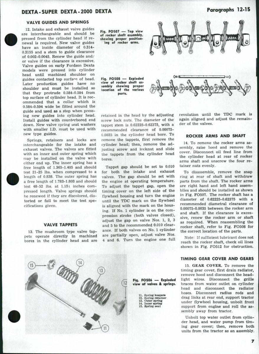
After reinstalling the valves in their
appropriate seats, the maximum
clearance between the top of the
valve head and the face of the cylin-
der head should be measured using a
straight edge and feeler gage or spe-
cial depth gage, as shown in Fig.
FO505. If the clearance for any valve
exceeds 0.140, the valve must be re-
newed. If clearance is less than 0.059,
reface valve so that clearance is 0.059-
0.087. Valve stem diameter is 0.311-
0.312.
Fig. FO505 — Measuring
vaive head clearance
with speciai depth gage.
A straight edge and feei-
er gage may be used. If
ciearance exceeds 0.140,
vaive should be renewed.
DEXTA-SUPER DEXTA-2000 DEXTA
Paragraphs 12-15
VALVE GUIDES AND SPRINGS
12. Intake and exhaust valve guides
are interchangeable and should be
pressed from the cylinder head if re-
newal is required. New valve guides
have an inside diameter of 0.314-
0.3155 and a stem to guide clearance
of 0.002-0.0045. Renew the guide and/
or valve if the clearance is excessive.
Valve guides on early Fordson Dexta
models were pressed into cylinder
head until machined shoulder on
guides contacted top surfa'^e of head.
Later production guides have no
shoulder and must be installed so
that they protrude 0.584-0.594 from
top surface of cylinder head. It is rec-
ommended that a collar which is
0.584-0.594 wide be fitted around the
guide and used as a stop when press-
ing new guides into cylinder head.
Install guides with count*»rbored end
down. New valve spring seat washers
with smaller I.D. must be used with
new type guides.
Springs, retainers and locks are
interchangeable for the intake and
exhaust valves. The valves are fitted
with an inner and outer spring which
may be installed on the valve with
either end up. The inner spring has a
free length of 1.365-1.405 and should
test 21-25 lbs. when compressed to a
length of 0.838. The outer spring has
a free length of 1.783-1.803 and should
test 48-52 lbs. at 1.151 inches com-
pressed length. Valve springs should
be renewed if they are discolored, dis-
torted or fail to meet the test spe-
cifications given.
VALVE TAPPETS
13. The mushroom type valve tap-
pets operate directly in machined
bores in the cylinder head and are
Fig. FO507 — Top view
of rocicer shaft assembiy,
showing proper position-
ing of rocker arms.
Fig. FO508 — Expioded
view of rocker shaft as-
sembiy showing proper
location of the various
parts.
retained in the head by the adjusting
screw lock nuts. The diameter of the
tappet stem is 0.62225-0.62375, with a
recommended clearance of 0.00075-
0.0035 in the cylinder head bore. To
remove the tappets, first remove the
cylinder head; then, remove the ad-
justing screw and locknut and slide
the tappets from the cylinder head
bores.
Tappet gap should be set to 0.010
for both the intake and exhaust
valves. The gap should be set with
the engine at operating temperature.
To adjust the tappet gap, open the
timing cover on the left side of the
flywheel housing and turn the engine
until the TDC mark on the flywheel
is aiigned with the mark on the hous-
ing. If No. 1 cylinder is on the com-
pression stroke (both valves closed),
adjust the gap on valve Nos. 1, 2, 3
and 5 to the recommended 0.010 clear-
ance. If both valves on No. 1 cylinder
are partially open, adjust valve Nos.
4 and 6. Turn the engine one full
revolution until the TDC mark is
again aligned and adjust the remain-
der of the valves.
ROCKER ARMS AND SHAFT
14. To remove the rocker arms as-
sembly, raise hood and remove the
cover. Disconnect oil feed line from
the cylinder head at rear of rocker
arms shaft and unscrew the four re-
tainer nuts evenly.
To disassemble, remove the snap
ring at rear of shaft and withdraw
parts from the shaft. The rocker arms
are right hand and left hand assem-
blies and should be installed as shown
in Fig. FO507. The rocker shaft has a
diameter of 0.62225-0.62375 with a
recommended diametral clearance of
0.00075-0.0035 between the rocker arm
and shaft. If the clearance is exces-
sive, renew the rocker arm or shaft
as required. When reassembling the
rocker shaft, refer to Fig. FO508 for
the correct location of the parts.
Note: If sufficient lubricant does not
reach the rocker shaft, check oil lines
shown in Fig. FO512 for obstruction.
Fig. FO506 ~ Expioded
view of vaives & springs.
11. Spring keepers
12. Spring retainer
13. Outer spHncr
14. Inner spring
15. Spring seat
TIMING GEAR COVER AND GEARS
15. GEAR COVER. To remove the
timing gear cover, first drain radiator,
remove hood and disconnect the head-
light wires. Disconnect the grille
braces from water outlet on cylinder
head and disconnect the radiator
hoses. Disconnect radius rods and
drag links at rear end, support tractor
under flywheel housing, unbolt front
support from engine and roll the as-
sembly away from tractor.
Unbolt top water outlet from cylin-
der head, and water pump from tim-
ing gear cover; then, remove both
units from the tractor as an assembly.
Paragraphs 16-18
Remove the starting jaw and crank-
shaft pulley, then unbolt and remove
the timing gear cover. The crankshaft
front oil seal can be renewed at this
time and should be installed with a
suitable driver so that lip faces rear
of engine.
16. TIMING GEARS. Before remov-
ing any gears in the timing gear train,
first remove rocker arm cover and
rocker arms assembly to avoid the
possibility of damage to the pistons or
valve train if either the camshaft or
crankshaft should be turned inde-
pendently of the other.
The timing gear train consists of the
crankshaft gear, camshaft gear, pump
drive gear and an idler gear connect-
ing the other three gears of the train.
Timing gear backlash should be
0.003-0.006 between the idler gear
and any of the other timing gears.
Replacement gears are available in
standard size only. If backlash is not
within recommended limits, renew
the idler gear, idler gear shaft and/or
any other gears concerned.
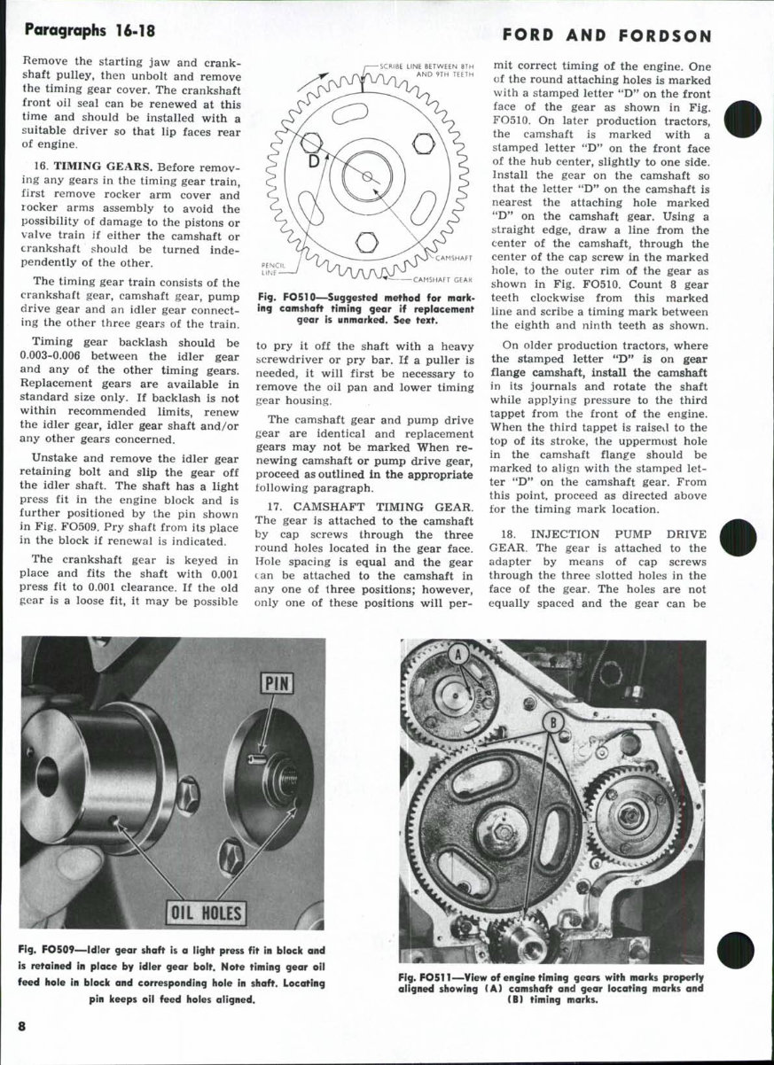
Unstake and remove the idler gear
retaining bolt and slip the gear off
the idler shaft. The shaft has a light
press fit in the engine block and is
further positioned by the pin shown
in Fig. FO509. Pry shaft from its place
in the block if renewal is indicated.
The crankshaft gear is keyed in
place and fits the shaft with 0.001
press fit to 0.001 clearance. If the old
gear is a loose fit, it may be possible
SCRIBE LINE BETWEEN 8TH
AND 9TH TEETH
CAMSHAFT GEAR
Fig. FO510—Suggested method for mark-
ing camshaft timing gear if replacement
gear is unmarked. See text.
to pry it off the shaft with a heavy
screwdriver or pry bar. If a puller is
needed, it will first be necessary to
remove the oil pan and lower timing
gear housing.
The camshaft gear and pump drive
gear are identical and replacement
gears may not be marked When re-
newing camshaft or pump drive gear,
proceed as outlined in the appropriate
following paragraph.
17. CAMSHAFT TIMING GEAR.
The gear is attached to the camshaft
by cap screws through the three
round holes located in the gear face.
Hole spacing is equal and the gear
can be attached to the camshaft in
any one of three positions; however,
only one of these positions will per-
FORD AND FORDSON
mit correct timing of the engine. One
of the round attaching holes is marked
with a stamped letter "D" on the front
face of the gear as shown in Fig.
FO510. On later production tractors,
the camshaft is marked with a
stamped letter "D" on the front face
of the hub center, slightly to one side.
Install the gear on the camshaft so
that the letter "D" on the camshaft is
nearest the attaching hole marked
"D" on the camshaft gear. Using a
straight edge, draw a line from the
center of the camshaft, through the
center of the cap screw in the marked
hole, to the outer rim of the gear as
shown in Fig. FO510. Count 8 gear
teeth clockwise from this marked
line and scribe a timing mark between
the eighth and ninth teeth as shown.
On older production tractors, where
the stamped letter *'D" is on gear
flange camshaft, install the camshaft
in its journals and rotate the shaft
while applying pressure to the third
tappet from the front of the engine.
When the third tappet is raisevl to the
top of its stroke, the uppermost hole
in the camshaft flange should be
marked to align with the stamped let-
ter "D*' on the camshaft gear. From
this point, proceed as directed above
for the timing mark location.
18. INJECTION PUMP DRIVE
GEAR. The gear is attached to the
adapter by means of cap screws
through the three slotted holes in the
face of the gear. The holes are not
equally spaced and the gear can be
Fig. FOS09—idler gear shaft is a light press fit In biock and
is retained in piace by idier gear boit. Note timing gear oil
feed hoie in biock and corresponding hole in shaft. Locating
pin keeps oii feed holes aligned.
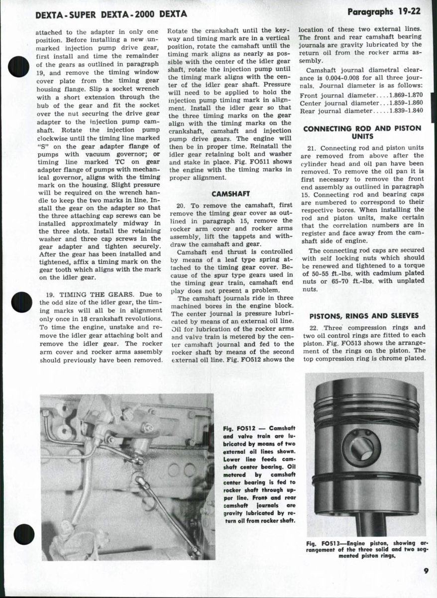
Fig. F0511—View of engine timing gears with marks properiy
aiigned showing (A) camshaft and gear iocating marks and
(B) timing marks.
8
DEXTA-SUPER DEXTA-2000 DEXTA
Paragraphs 19-22
attached to the adapter in only one
position. Before installing a new un-
marked injection pump drive gear,
first install and time the remainder
of the gears as outlined in paragraph
19, and remove the timing window
cover plate from the timing gear
housing flange. Slip a socket wrench
with a short extension through the
hub of the gear and fit the socket
over the nut securing the drive gear
adapter to the injection pump cam-
shaft. Rotate the injection pump
clockwise until the timing line marked
"S" on the gear adapter flange of
pumps with vacuum governor; or
timing line marked TC on gear
adapter flange of pumps with mechan-
ical governor, aligns with the timing
mark on the housing. Slight pressure
will be required on the wrench han-
dle to keep the two marks in line. In-
stall the gear on the adapter so that
the three attaching cap screws can be
installed approximately midway in
the three slots. Install the retaining
washer and three cap screws in the
gear adapter and tighten securely.
After the gear has been installed and
tightened, affix a timing mark on the
gear tooth which aligns with the mark
on the idler gear.
19. TIMING THE GEARS. Due to
the odd size of the idler gear, the tim-
ing marks will all be in alignment
only once in 18 crankshaft revolutions.
To time the engine, unstake and re-
move the idler gear attaching bolt and
remove the idler gear. The rocker
arm cover and rocker arms assembly
should previously have been removed.
Rotate the crankshaft until the key-
way and timing mark are in a vertical
position, rotate the camshaft until the
timing mark aligns as nearly as pos-
sible with the center of the idler gear
shaft, rotate the injection pump until
the timing mark aligns with the cen-
ter of the idler gear shaft. Pressure
will need to be applied to hold the
injection pump timing mark in align-
ment. Install the idler gear so that
the three timing marks on the gear
align with the timing marks on the
crankshaft, camshaft and injection
pump drive gears. The engine will
then be in proper time. Reinstall the
idler gear retaining bolt and washer
and stake in place. Fig. FO511 shows
the engine with the timing marks in
proper alignment.
CAMSHAFT
20. To remove the camshaft, first
remove the timing gear cover as out-
Uned in paragraph 15, remove the
rocker arm cover and rocker arms
assembly, lift the tappets and with-
draw the camshaft and gear.
Camshaft end thrust is controlled
by means of a leaf type spring at-
tached to the timing gear cover. Be-
cause of the spur type gears used in
the timing gear train, camshaft end
play does not present a problem.
The camshaft journals ride in three
machined bores in the engine block.
The center journal is pressure lubri-
cated by means of an external oil line.
Oil for lubrication of the rocker arms
and valvs train is metered by the cen-
ter camshaft journal and fed to the
rocker shaft by means of the second
external oil line. Fig. FO512 shows the
location of these two external lines.
The front and rear camshaft bearing
journals are gravity lubricated by the
return oil from the rocker arms as-
sembly.
Camshaft journal diametral clear-
ance is 0.004-0.008 for all three jour-
nals. Journal diameter is as follows:
Front journal diameter 1.869-1.870
Center journal diameter.. .1.859-1.860
Rear journal diameter 1.839-1.840
CONNECTING ROD AND PISTON
UNITS
21. Connecting rod and piston units
are removed from above after the
cylinder head and oil pan have been
removed. To remove the oil pan it is
first necessary to remove the front
end assembly as outlined in paragraph
15. Connecting rod and bearing caps
are numbered to correspond to their
respective bores. When installing the
rod and piston units, make certain
that the correlation numbers are in
register and face away from the cam-
shaft side of engine.
The connecting rod caps are secured
with self locking nuts which should
be renewed and tightened to a torque
of 50-55 ft,-lbs. with cadmium plated
nuts or 65-70 ft.-lbs. with unplated
nuts.
PISTONS, RINGS AND SLEEVES
22. Three compression rings and
two oil control rings are fitted to each
piston. Fig. FO513 shows the arrange-
ment of the rings on the piston. The
top compression ring is chrome plated.
Fig. FO512 — Camshaft
and vaive train are iu-
bricated by means of two
external oil lines shown.
Lower iine feeds cam-
shaft center bearing. Oii
metered by camshaft
center bearing is fed to
rocker shaft through up-
per iine. Fron» and rear
camshaft lournals are
gravity tubricated by re-
turn oii from rocker shaft.
Fig. FO513—Engine piston, showing ar-
rangement of the three solid and two seg-
mented piston rings.
Paragraphs 23-25
FORD AND FORDSON
The third compression ring and the
top oil control ring are of laminated
steel construction. End gap of these
rings should be as follows:
Third compression ring.. .0.008-0.010
Top oil control ring 0.018-0.037
Installation of the first and second
compression rings and the lower oil
control ring is conventional. These
rings should have 0.002-0.004 side
clearance in the ring grooves and end
gaps as follows:
First compression ring 0.010-0.015
Second compression ring.. .0.009-0.013
Lower oil control ring 0.009-0.013
The solid rings are non-directional
and may be installed either side up.
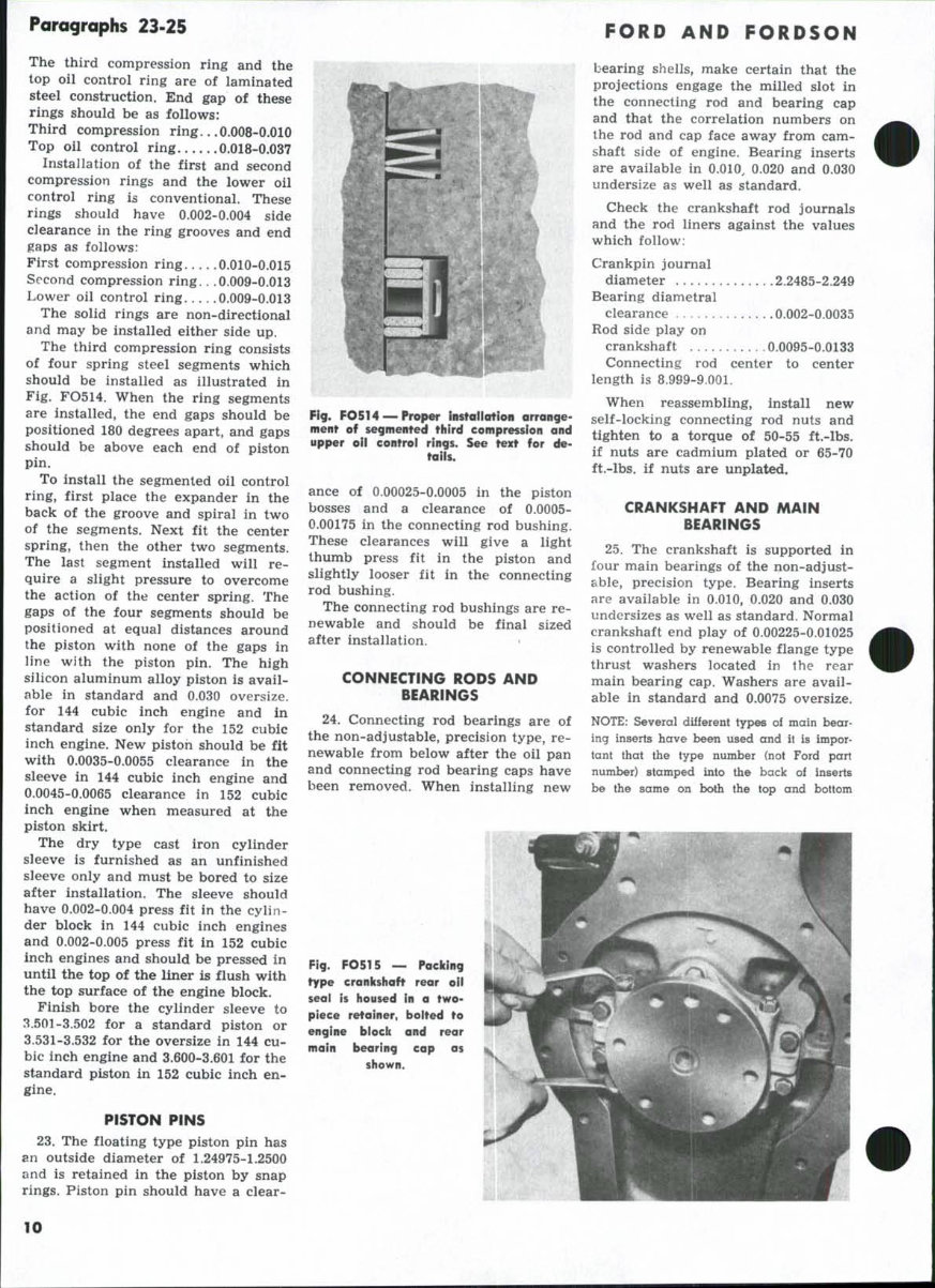
The third compression ring consists
of four spring steel segments which
should be installed as illustrated in
Fig. FO514. When the ring segments
are installed, the end gaps should be
positioned 180 degrees apart, and gaps
should be above each end of piston
pin.
To install the segmented oil control
ring, first place the expander in the
back of the groove and spiral in two
of the segments. Next fit the center
spring, then the other two segments.
The last segment installed will re-
quire a slight pressure to overcome
the action of the center spring. The
gaps of the four segments should be
positioned at equal distances around
the piston with none of the gaps in
line with the piston pin. The high
silicon aluminum alloy piston is avail-
able in standard and 0.030 oversize,
for 144 cubic inch engine and in
standard size only for the 152 cubic
inch engine. New piston should be fit
with 0.0035-0.0055 clearance in the
sleeve in 144 cubic inch engine and
0.0045-0.0065 clearance in 152 cubic
inch engine when measured at the
piston skirt.
The dry type cast iron cylinder
sleeve is furnished as an unfinished
sleeve only and must be bored to size
after installation. The sleeve should
have 0.002-0,004 press fit in the cylin-
der block in 144 cubic inch engines
and 0.002-0.005 press fit in 152 cubic
inch engines and should be pressed in
until the top of the liner is flush with
the top surface of the engine block.
Finish bore the cylinder sleeve to
3.501-3.502 for a standard piston or
3.531-3.532 for the oversize in 144 cu-
bic inch engine and 3.600-3.601 for the
standard piston in 152 cubic inch en-
gine.
PISTON PINS
23. The floating type piston pin has
an outside diameter of 1.24975-1.2500
and is retained in the piston by snap
rings. Piston pin should have a clear-
Fig. FO5T4 — Proper instoMotiofi arrange-
ment of segmented third compression ond
upper oil control rings. See text for de-
tails.
ance of 0.00025-0.0005 in the piston
bosses and a clearance of 0.0005-
0.00175 in the connecting rod bushing.
These clearances will give a light
thumb press fit in the piston and
slightly looser fit in the connecting
rod bushing.
The connecting rod bushings are re-
newable and should be final sized
after installation.
CONNECTING RODS AND
BEARINGS
24. Connecting rod bearings are of
the non-adjustable, precision type, re-
newable from below after the oil pan
and connecting rod bearing caps have
been removed. When installing new
bearing shells, make certain that the
projections engage the milled slot in
the connecting rod and bearing cap
and that the correlation numbers on
the rod and cap face away from cam-
shaft side of engine. Bearing inserts
are available in 0.010, 0.020 and 0.030
undersize as well as standard.
Check the crankshaft rod journals
and the rod liners against the values
which follow:
Crankpin journal
diameter 2.2485-2.249
Bearing diametral
clearance 0.002-0.0035
Rod side play on
crankshaft 0.0095-0.0133
Connecting rod center to center
length is 8.999-9.001.
When reassembling, install new
self-locking connecting rod nuts and
tighten to a torque of 50-55 ft.-lbs.
if nuts are cadmium plated or 65-70
ft.-lbs. if nuts are unplated.
CRANKSHAFT AND MAIN
BEARINGS
25. The crankshaft is supported in
four main bearings of the non-adjust-
able, precision type. Bearing inserts
are available in 0.010, 0.020 and 0.030
undersizes as well as standard. Normal
crankshaft end play of 0.00225-0.01025
is controlled by renewable flange type
thrust washers located in the rear
main bearing cap. Washers are avail-
able in standard and 0.0075 oversize.
NOTE: Several diiferent types of main bear-
ing inserts have been used and it is impor-
tant that the type number (not Ford part
number) stamped into the back oi inserts
be the same on both the top and bottom
Fig. FO515 — Packing
type crankshaft rear oil
seal is housed in a two-
piece retainer, bolted to
engine block and rear
main bearing cap as
shown.
10
DEXTA-SUPER DEXTA-2000 DEXTA
Paragraphs 26-28
Insert of any one bearinc, journal. It is rec-
ommended that the main bearing inserts be
all of one type number. Also, the locking tab
on the bottom Gaearing cap) thrust washer
has been changed in production at engine
Serial No. 1449364 and the correct thrust
washer must be used.
To remove the front main bearing
cap, it is first necessary to remove
the timing gear cover, lower timing
gear housing and oil pump. To re-
move the rear main bearing cap, it is
first necessary to remove the engine
as outlined in paragraph 9 and re-
move the clutch, flywheel, adapter
plate and rear oil seal retainer.
Check the crankshaft and main
bearing inserts against the values
which follow:
Crankpin diameter 2.2485-2.249
Main journal diameter.. .2.7485-2.749
Main bearing diametral
clearance 0.0025-0.0045
Main bearing bolt
torque .90-95 ft.-lbs.
CRANKSHAFT OIL SEALS
26. The crankshaft front oil seal is
mounted in the timing gear cover and
may be renewed after the front cover
is removed. Removal procedure for
the timing gear cover is outlined in
paragraph 15. Press the new seal into
the cover with the lip to the inside.
The crankshaft rear oil seal can be
renewed after detaching engine from
clutch housing as outlined in para-
graph 56 and removing the clutch,
flywheel and engine adapter plate.
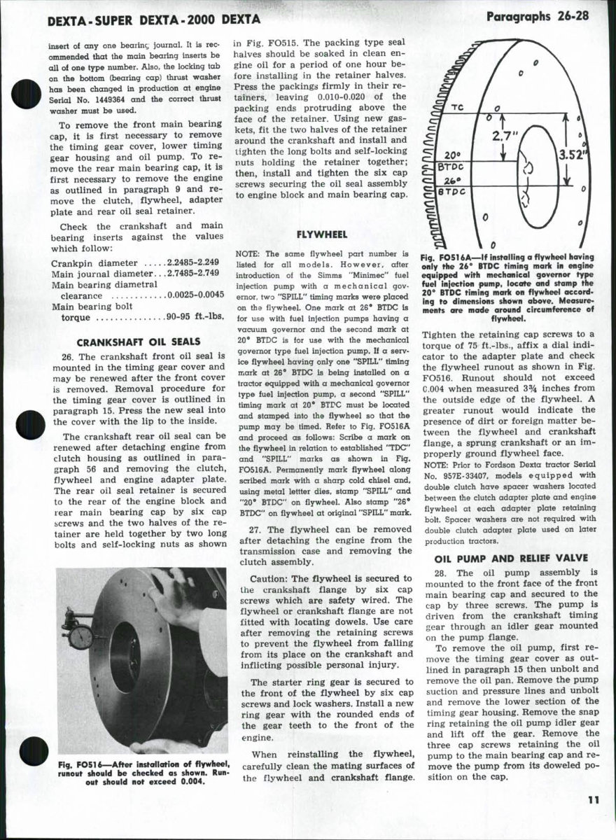
The rear oil seal retainer is secured
to the rear of the engine block and
rear main bearing cap by six cap
screws and the two halves of the re-
tainer are held together by two long
bolts and self-locking nuts as shown
Fig. FO516—After insfallatioii of
runout should be eliecked as shown. Run-
out shouid not exceed 0.004.
in Fig. FO515. The packing type seal
halves should be soaked in clean en-
gine oil for a period of one hour be-
fore installing in the retainer halves.
Press the packings firmly in their re-
tainers, leaving 0.010-0.020 of the
packing ends protruding above the
face of the retainer. Using new gas-
kets, fit the two halves of the retainer
around the crankshaft and install and
tighten the long bolts and self-locking
nuts holding the retainer together;
then, install and tighten the six cap
screws securing the oil seal assembly
to engine block and main bearing cap.
FLYWHEEL
NOTE: The same flywheel part number is
listed for all models. However, after
introduction of the Simms "Minimec" fuel
injection pump with a m e c h a n i c a l gov-
ernor, two "SPILL" timing marks were placed
on the flywheel. One mark at 26' BTDC is
for use with fuel injection pumps having a
vacuum governor and the second mark at
20" BTDC is lor use with the mechanical
governor type fuel injection pump. If a serv-
ice flywheel having only one "SPILL" timing
mark at 26" BTDC is being installed on a
tractor equipped with a mechanical governor
type fuel injection pump, a second "SPILL"
timing mark at 20* BTDC must be located
and stamped into the flywheel so that the
pump may be timed. Refer to Fig. FO516A
and proceed as follows: Scribe a mark on
the flywheel in relation to established "TDC"
and "SPILL" marks as shown in Fig.
FO516A. Permanently mark flywheel along
scribed mark with a sharp cold chisel and,
using metal lettter dies, stamp "SPILL" and
"20* BTDC" on flywheel. Also stamp "26"
BTDC" on flywheel at original "SPILL" mark.
27. The flywheel can be removed
after detaching the engine from the
transmission case and removing the
clutch assembly.
Caution: The flywheel is secured to
the crankshaft flange by six cap
screws which are safety wired. The
flywheel or crankshaft flange are not
fitted with locating dowels. Use care
after removing the retaining screws
to prevent the flywheel from falling
from its place on the crankshaft and
inflicting possible personal injury.
The starter ring gear is secured to
the front of the flywheel by six cap
screws and lock washers. Install a new
ring gear with the rounded ends of
the gear teeth to the front of the
engine.
When reinstalling the flywheel,
carefully clean the mating surfaces of
the flywheel and crankshaft flange.
Fig. FO516A—If insfalling a flywkeel having
only the 26" BTDC timing mark in engine
equipped wirh mechanical governor type
fuel infection pump, locate and stamp the
20** BTDC timing mark on flywheel accord-
ing to dimensions shown above. Measure-
ments ore made around circumference of
flywheel.
Tighten the retaining cap screws to a
torque of 75 ft.-lbs., affix a dial indi-
cator to the adapter plate and check
the flywheel runout as shown in Fig.
FO516. Runout should not exceed
C.004 when measured 3% inches from
the outside edge of the flywheel. A
greater runout would indicate the
presence of dirt or foreign matter be-
tween the flywheel and crankshaft
flange, a sprung crankshaft or an im-
properly ground flywheel face.
NOTE: Prior to Fordson Dexta tractor Serial
No. 957E-33407, models equipped with
double clutch have spacer washers located
between the clutch adapter plate and engine
flywheel at each adapter plate retaining
bolt. Spacer washers are not required with
double clutch adapter plate used on later
production tractors.
OIL PUMP AND RELIEF VALVE
28. The oil pump assembly is
mounted to the front face of the front
main bearing cap and secured to the
cap by three screws. The pump is
driven from the crankshaft timing
gear through an idler gear mounted
on the pump flange.
To remove the oil pump, first re-
move the timing gear cover as out-
lined in paragraph 15 then unbolt and
remove the oil pan. Remove the pump
suction and pressure lines and unbolt
and remove the lower section of the
timing gear housing. Remove the snap
ring retaining the oil pump idler gear
and lift off the gear. Remove the
three cap screws retaining the oil
pump to the main bearing cap and re-
move the pump from its doweled po-
sition on the cap.
11
You're Reading a Preview
What's Included?
Fast Download Speeds
Online & Offline Access
Access PDF Contents & Bookmarks
Full Search Facility
Print one or all pages of your manual
$26.99
Viewed 79 Times Today


Secure transaction
What's Included?
Fast Download Speeds
Online & Offline Access
Access PDF Contents & Bookmarks
Full Search Facility
Print one or all pages of your manual
$26.99
This workshop manual is an essential resource for FMD tractor owners looking to save on repair and servicing costs. It contains extensive detailed diagrams, technical references, and step-by-step guides to assist in carrying out repairs and servicing. Whether you are a professional mechanic or a DIY enthusiast, this comprehensive package is a must-have for maintaining your Ford tractor.
- Comprehensive catalogue of workshop manuals for FMD tractors
- Supplied in PDF format for easy printing
- Extensive detailed diagrams and technical references
- Step-by-step guides for repair and servicing


