

P Repair Manual
r":
i,r'y . ; ," \
:"
f :,, ,I;,+;<:, , ; .
b.+$ :.E. , ,-,,
,.: . , ., . , $ ,_.
, FORDSON
1
POWER MAJOR
SUPER M
THE NElU
MANUFACTURED IN ENGLAND BY
FORD MOTOR COMPANY LTD.

FOREWORD
This manual is written to assist in the efficient repair of
the New Fordson Major Tractor. Wherever possible,
each operation is self-contained and sufficient detail is
given to ensure that unnecessary dismantling will be
avoided.
Special tools have been developed to assist when
carrying out the work and reference has been made to
these tools in the appropriate places. The tools are
numbered according to the Basic Part Number of the
component in question.
All necessary specifications, repair data and wear limits
are quoted at the end of each section and will be of
assistance when deciding if pans are suitable for further
service.
Whenever reference is made to the right- and left-
hand side of the tractor, this is as viewed from the
Driver's seat, facing forward.
The tractor number is the same as the engine number
which is stamped on the left-hand top face of the flywheel
housing flange. This number is also stamped on a plate
attached to the engine front bulkhead.
Ford Policy is one of continuous imprmement and the
right to change prices, specijicat~on and equipment at any
time without notice is resmed.
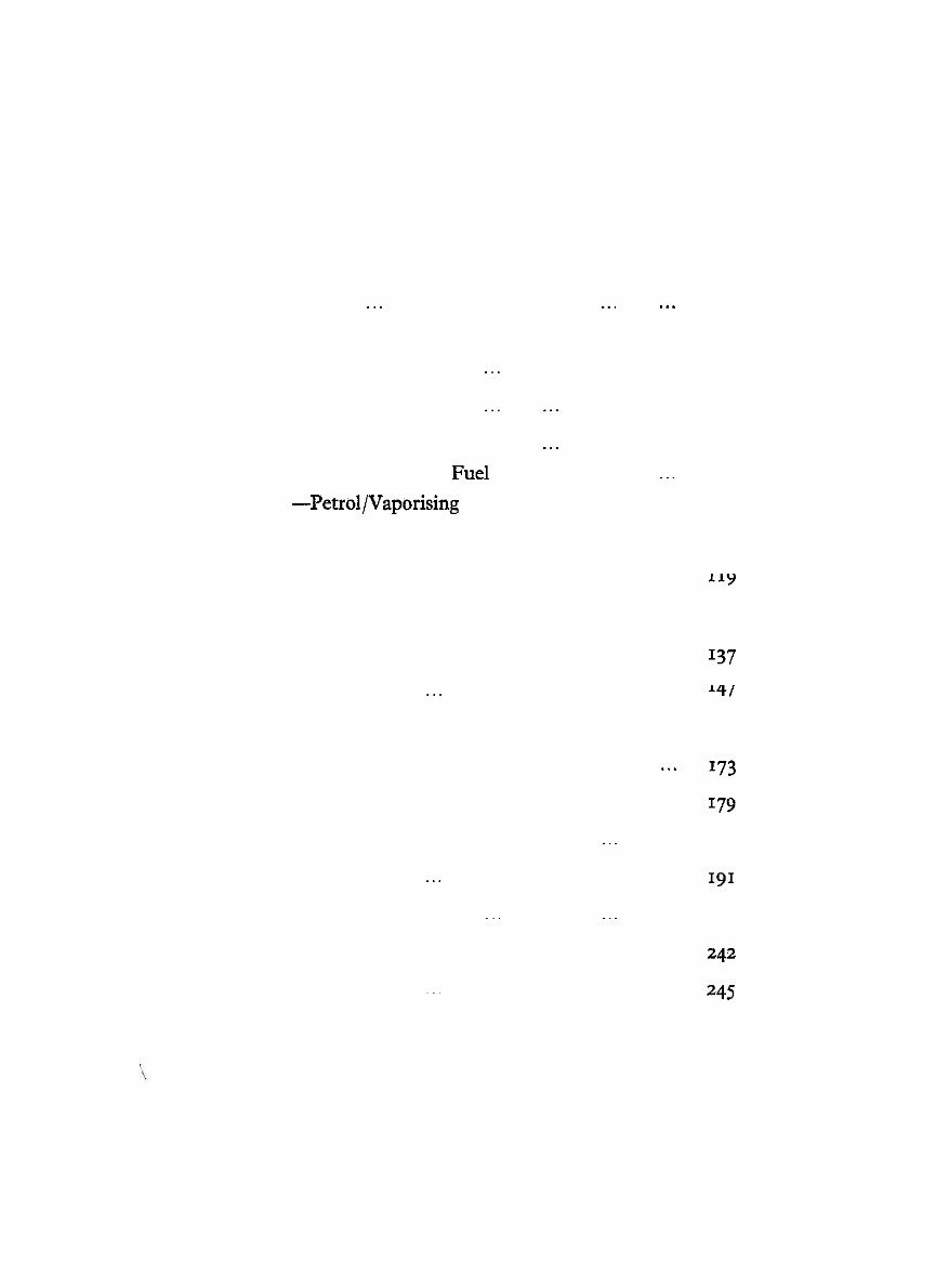
CONTENTS
7
SECTION PAGE NO.
Engine--Diesel ... ... ... ... ... ... 5
- Petrol - Vaporising Oil ... ... ... ... 35
- Lubrication System ... ... ... ... 59
... Cooling System ... ... ... ... ... 68
Fuel System- Diesel ... ... ... ... ... 75
- Fuel Tanks and Fuel Supply Taps ... 99
-Petrol/Vaporising Oil ... ... ... 103
Separating the Tractor ... ... ... ... ... 115
... ... Clutch ... ... ... ... ... ... 119
Front Transmission- Gearbox ... ... ... ... 129
Rear Transmission- Rear Axle ... ... ... ... 137
Hydraulic System ... ... ... ... ... ... I47
Front Axle ... ... ... ... ... ... ... 167
Steering Gear ... ... ... ... ... ... 173
Braking System . . ... ... ... ... ... 179
Wheels and Tyres ... ... ... ... ... ... 187
... ... ... Electrical System ... ... ... 191
Power Take- off Equipment ... ... ... ... 231
Index ... ... ... ... ... ... ... ... 242
Supplement ... ... .. ... ... ... ... 245
COPYRIGHT IN GREAT BRITAIN, JANUARY 1954.
~epmductio in any manner, in whole or in parr, prohibircd
without the express pcrrni.sion in wiring of Ford Moror
Company Limited, 88 Regcnr Strccq London, W.,, England.
THE DIESEL ENGINE
The 3.61 litre, four cylinder, direct injection type diesel
engine fitted in the New Fordson Major Tractor has a bore
diameter of 100 mm, and a stroke of 115 mm.
0verhead7valves are employed operated by push rods from
a gear driven camshaft located in the right-hand side of the
cylinder block. The compression ratio is 16 to 1.
The valves are fitted vertically in the cylinder head, the
inlet valve head being larger than the exhaust. The valve
guides are replaceable.
Aluminium alloy pistons are employed with a combustion
chamber machined in the crowns and have three cornprcrsion
rings and one oil ring above the piston pin and one oii control
ring below the piston pin. T h e piston pins are fully floating
and are retained in position by two circlips.
Detachable wet cylinder liners are fitted, flange-mounted
in the top face of the cylinder block and retained in position
by the cylinder head.
The crankshaft is supported in five large diameter main
bearings. These bearings and the connecting rod big end
bearings are of the detachable steel-backed lead-bronze type.
Crankshaft end-float is controlled by detachable thrust
washers fitted at each side of the centre main bearing.
An enclosed camshaft type fuel injection pump is driven
from the rear end of the auxiliary drive shaft and feeds
multi-holed type injectors located at an angle in the top of
the cylinder head.
The engine speed is controlled by a pneumatic governor
mouuted on the f~e injedon pump. An excess fuel device
is fitted to assist cold starting.
On current engines rotator type exhaust valves are fitted.
A cap located over the end of the valve stem transmits
pressure from the rocker lever to the spring retainer and
valve spring. This anion allows the valve to remain free
throughout its operating cycle.
A decompressor, operating on all valves, was fitted to early
type engines. On current engines this is optional equipment.
Note - The operations described in the following pages are
each complete in themselves and used in conjunction
with the instructions from page 31 onwards give
detailed information for a complete engine strip down
and rebuild.
These instructions have been prepared in orderthat the
operations mqy be completed in the quickest time, involving
the removal of the least number of component parts.
A guide as to whether a part is fit for re-use or not is given
in the form of wear limits tabulated at the end of the section.
In the case of a complete overhaul of the engine, discretion
must be exercised when re-fitting parts which, although
within the limits, may be subject to arduous service when
reassembled.
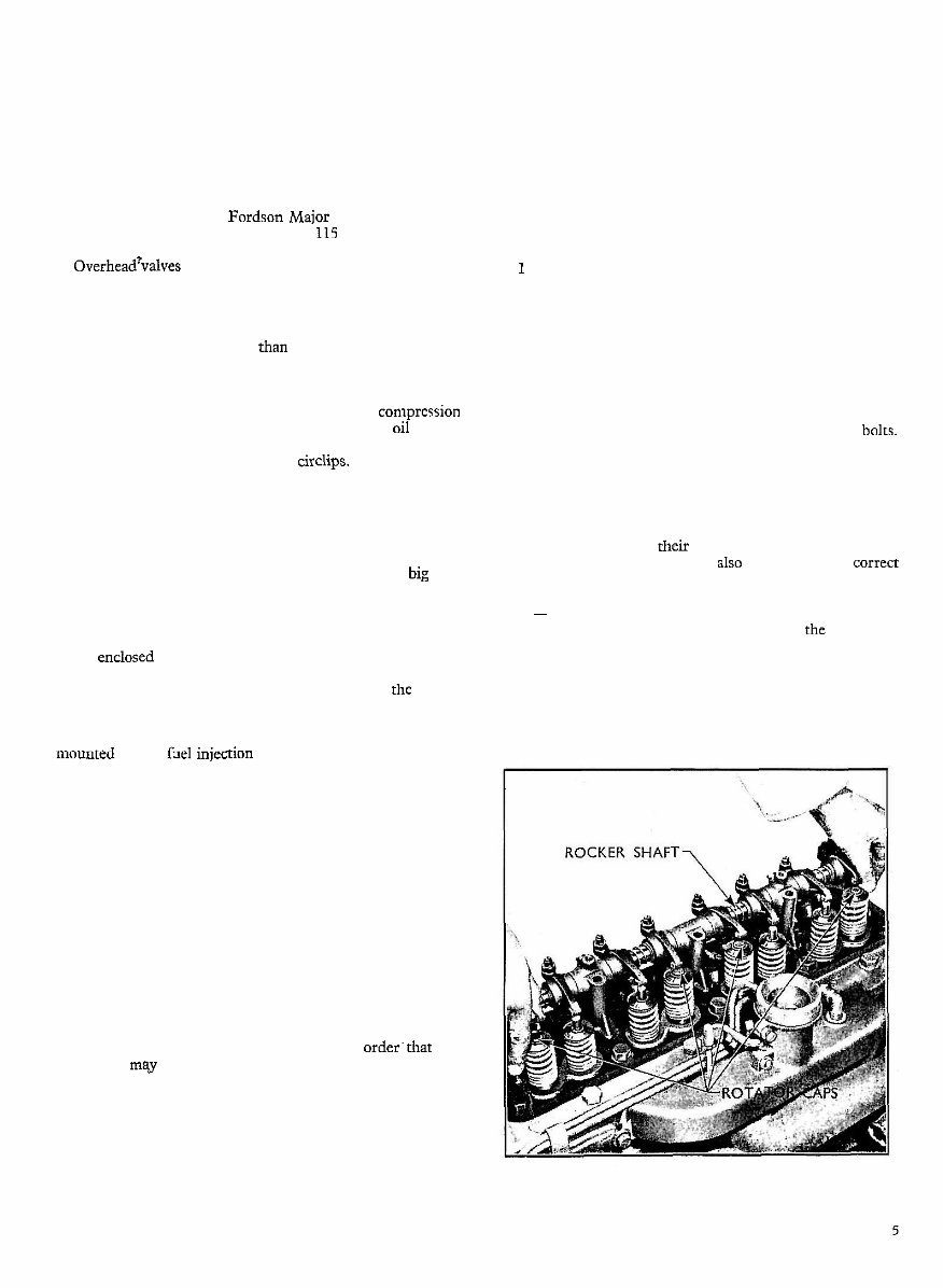
THE ROCKER SHAFT ASSEMBLY
To Remove
1 Undo the adaptor nut securing the ventilation pipe
from the rocker cover to the inlet manifold.
2 Unscrew the two securing bolts and remove the rocker
cover and gasket.
3 Release the retaining nut on the decompressor control
(where fitted) and disengage the inner end of the
control from the rocker shaft lever.
4 Release the tab washers on the five rocker shaft bolts.
Gradually unscrew the bolts and lift off the rocker
shaft, taking care not to dislodge the rotator caps from
the exhaust valves if this type of valve assembly is
fitted. (See Fig. 1.)
5 Lift out the push rods from their block locations,
keeping them in their correct order and remove the
rotator caps which should also be kept in their correct
order.
Note - I t is possible to change a push rod without removing
the rocker shaft. This is done in the following
manner: make sure that the valve in question is
closed, slide the valve rocker sideways off the valve
stem, until its ball end can be disengaged from the
push rod cup.
Fig. 1
Removing the Rocker Shaft
ENGINE- DIESEL
To Dismantle
Note - Where a decompressor lever is not fitted the eccen-
tric sleeves and keys refened to are also not fitted, and
the build-up is similar to that used on the Petrol and
Vaporising Oil engines with the exception of the
rocker levers.
1 Stand the assembly on end with the decompressor
lever uppkmost, push the rocker levers, springs,
eccentric sleeves and support brackets downwards
until the pin retaining the decompressor lever or the
end plug is revealed. Remove the pin and withdraw
the decompressor lever or end plug assembly.
(See Fig. 3.)
2 Pull off the adjacent support bracket, then the two
rockers, spacer spring and eccentric sleeve. This will
disclose the eccentric sleeve key, which must be
removed before the next support bracket can be
pulled off the shaft. Remove the remaining parts in
a similar sequence and extract the keys as they are
revealed.
3 Finally, remove the front plug after removing the
retaining pin.
To Reassemble
1 Fit the front end plug and retaining pin to that end of
the shaft which has the pin hole centrally drilled.
2 Fit the support brackets, keys, eccentric sleeves,
rocker levers and spacer springs in their correct
order as shown in Fig. 2. The front and rear brackets
are interchangeable, as also are the intermediate
brackets, which are identified by a tapped hole for the
rocker cover bolt. Ensure that the support bracket
bolt holes are to the right viewing the shaft from the
front end, with each pair of rocker levers inclined
towards each other at the valve end.
Fig. 3
Decompressor Lever
3
Complete the assembly by pushing all the parts
towards the front of the rocker shaft and fitting the
decompressor lever and its retaining pin.
To Replace
1 Fit the push rods in their original position and place
the rotator caps on the exhaust valve stems if this type
of valve assembly is fitted. Care should be taken to
prevent these caps falling in the engine.
Fig. 2
Rocker Shaft and Supports
ENGINE- DIESEL
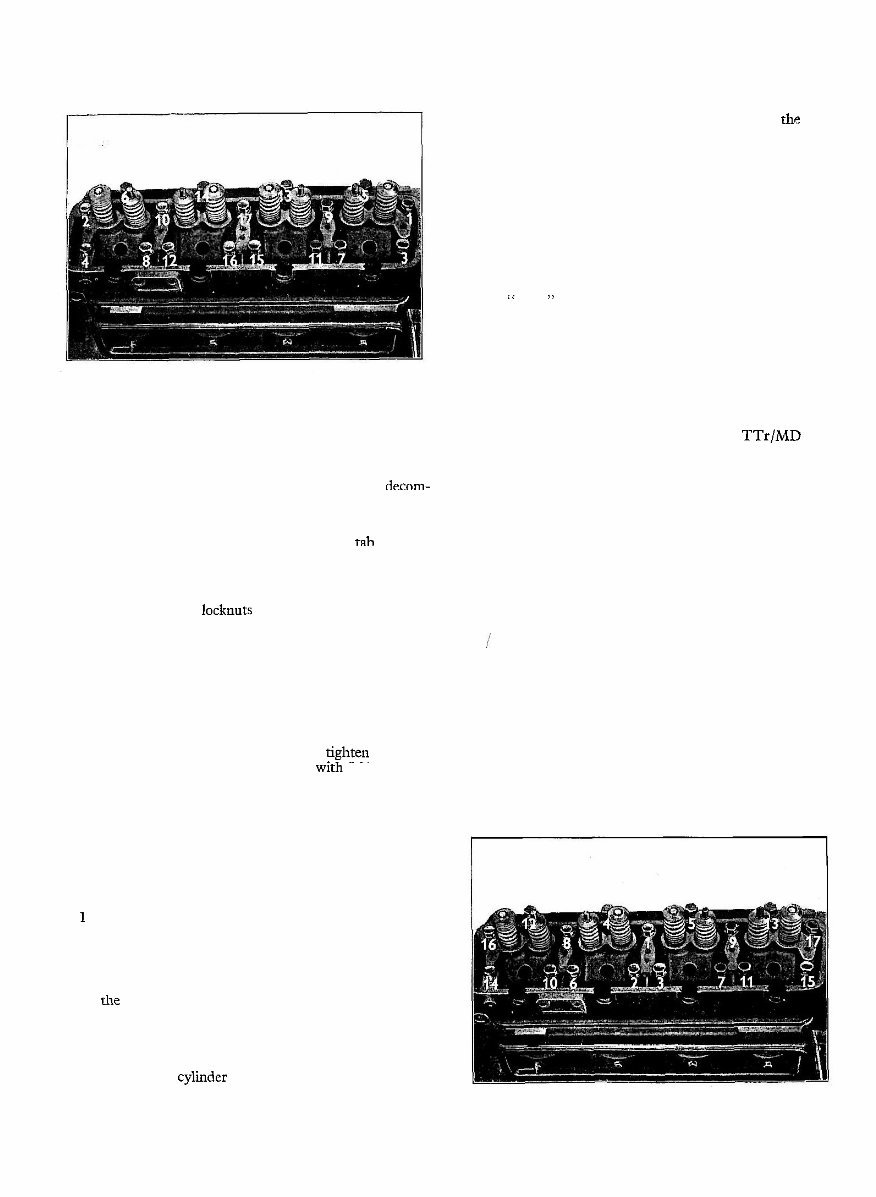
Fig. 4
Correct Sequence for Loosening Cylinder Head Bolts
2 Fit the rocker shaft to the cylinder head, entering the
adjusting screw ball ends in the push rod cups and
engage the decompressor control with the decom-
pressor lever.
3 Fit and tighten down evenly the five rocker shaft
support bracket bolts and lock with the tab washers.
4 Adjust the valve clearances initially to 0.015 in. for
inlet valves and exhaust valves without rotators.
Rotator type exhaust valves should be set to 0.012 in.
Ensure that all locknuts are tightened.
Note - Ensure that the decompressor control is pushed in
and the locking nut screwed in before carrying out
the valve adjustment.
5 Warm up the engine and if necessary readjust the valve
clearance to 0.015 in. for inlet valves and exhaust
valves without rotators and 0.012 m. for rotator type
exhaust valves.
6 Fit the rocker cover and gasket and fighten down the
two securing bolts which are fitted wlth folded copper
sealing washers.
7 Fit the ventilation suction pipe between the rocker
cover and the inlet manifold.
CYLINDER HEAD ASSEMBLY AND GASKET
T o Remove
1 Disconnect the negative cable from the battery
terminal post.
2 Remove the radiator filler cap and drain the
water from the cooling system through the two taps,
one on the radiator and one on the left-hand side of
the cylinder block.
3 Disconnect the radiator tie bar, remove the water
outlet connection and lift out the thermostat.
4 Remove the temperature gauge connection from the
front of the cylinder head.
5 Remove the rocker cover, gasket, rocker shaft and
push rods as described on page 5.
6 Remove the injectors as described in the Fuel
System Section.
7 Remove the inlet and exhaust manifolds as described
on page 8.
8 Unscrew the seventeen bolts retaining the cylinder
head to the cylinder block in the order shown in
Fig. 4.
9 Lift off the cylinder head and remove the gasket and
rocker shaft oil feed seal.
Note - Current type cylinder head bolts are marked
" 100 " on rhe head.
To Replace
1 Thoroughly clean off all dirt, carbon, etc., from the
cylinder block, cylinder head faces and the recess in
the cylinder block for the rocker shaft oil feed seal.
2 Fit a new rocker shaft oil feed seal and screw the
cylinder head locating studs (tool No. TTr/MD 6050)
into opposite corners of the cylinder block face and
locate the new cylinder head gasket in position.
3 Replace the cylinder head and screw in the seventeen
bolts and tighten in the correct order, as shown in
Fig. 5, to the correct torque shown in the specification.
4 Replace the inlet and exhaust manifolds as described
on page 8.
5 Replace the injectors as described in the Fuel System
Section.
6 Replace the rocker shaft, push rods, rocker cover and
gasket, and adjust valve clearances as described on
this page.
7 Replace the temperature gauge connection in the
front of the cylinder head.
8 Refit the thermostat, water outlet connection and the
radiator tie bar.
9 Refill the cooling system.
10 Reconnect the battery lead to the battery terminal
post.
Fig. 5
Correct Sequence for Tightening Cylinder Head Bolts
ENGINE- DIESEL
THE INLET AND EXHAUST MANIFOLDS
To Remove
1 Lift off the vertical type exhaust pipe. If the
horizontal type is fitted, disconnect the pipe at the
manifold.
2 Unscrew the clips at either end of the rubber hose
between the air cleaner and the inlet manifold and
remove the hose.
3 Disconnect the throttle control rod.
4 Disconnect, at the manifold end, the two suction pipes
from the pneumatic governor. Also disconnect and
remove the ventilation suction pipe between the
rocker cover and the inlet manifold.
5 Unscrew the manifold to head bolts and lift away the
manifolds.
i o Replace
1 Fit the manifolds using new gaskets, and screw in the
retaining bolts evenly, making sure that the clamping
washers are correctly positioned in their recesses.
2 Connect the pneumaticgovernor suction pipes, making
sure that the bleed pipe (i.e. the outer pipe on the
governor casing) is fitted to the upper connection on
the inlet manifold, and refit the ventilation suction
pipe between the rocker cover and the inlet manifold.
NOTE - THE ENGINE MUST NOT BE RUN WITH
THE GOVERNOR PIPES DISCONNECTED,
AS UNDER THESE CONDITIONS THE
GOVERNOR IS INOPERATIVE, AND SERIOUS
DAMAGE MAY RESULT.
3 Reconnect the throttle control rod.
4 Refit the rubber hose between the inlet manifold and
the air cleaner.
5 Replace the horizontaltype exhaust pipe with two bolts
and a nut, or if vertical type, replace in adaptor.
VALVES, GUIDES AND SPRINGS
The valves are mounted vertically in the cylinder head
and operated from the camshaft by conventional type push
rods and rocker arms. The diameter of the inlet valve head
is greater than that of the exhaust valve to improve engine
breathing.
On current engines rotator type exhaust valves are fitted
and the operation of these is described overleaf. The
inlet valve on aU engines remains the same.
Oil seals are fitted to the stems of aU valves with the
exception of the rotator type exhaust valves.
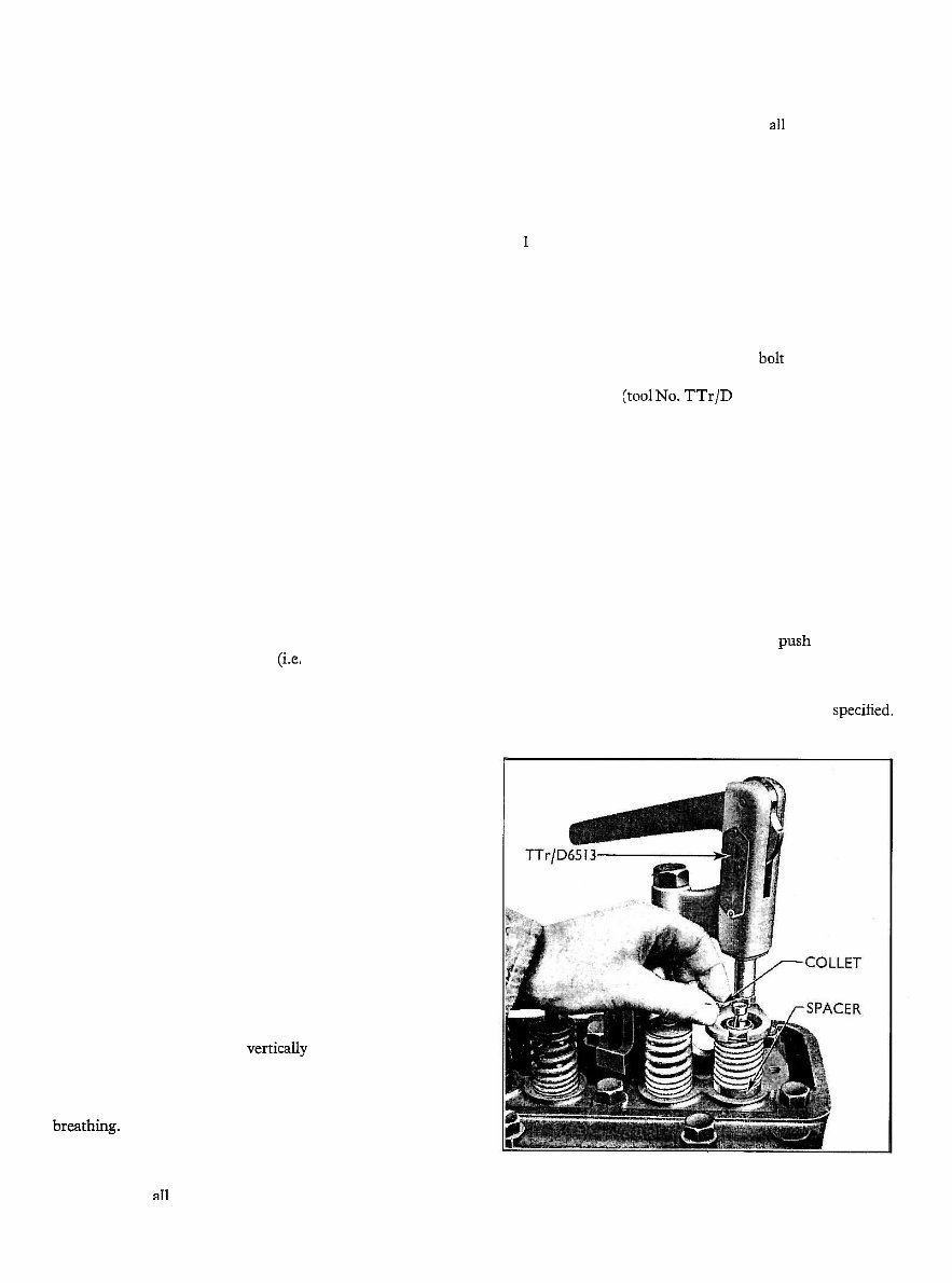
To Renew a Valve Spring (without removing the
cylinder head)
1 Remove the rocker cover and rocker shaft assembly,
push rods and rotator caps (if fitted), as described on
page 5.
2 Turn the piston on the cylinder beneath the valve
affected, to the top of its stroke.
3 Refit a rocker shaft support bolt adjacent to the
affected valve, slide the block of the valve spring
compressor (toolNo. TTr/D 6513) under the bolt head
and tighten down the bolt. Pull down the cam
handle to compress the valve and extract the collets.
(See Fig. 6.)
4 Release the cam handle and remove the spring
retainer, valve spring and rubber sealing ring.
5 Fit a new valve spring with the close-coiled end to the
cylinder head and replace the spring retainer.
Compress the valve spring and fit a new rubber sealing
ring into the lower groove of the valve stem where
applicable and locate the collets.
6 Remove the tool and replace the push rods, rotator
caps, rocker shaft assembly and rocker cover, as
described on page 6.
7 Readjust the valve clearances to the figure specfied.
Fig. 6
Valve Spring Compressor
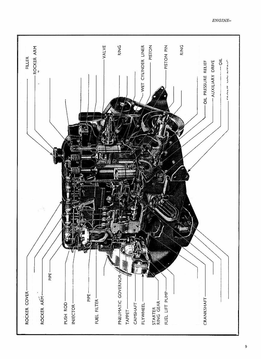
OIL FlLLER CAP
ROCKER ARM ADJUSTER
INJECTOR LEAK- OFF PIPE VALVE COLLET
V A L V E SPRING RETAINER
VALVE SPRING
INJECTOR PIPE THERMOSTAT
VALVE GUIDE
STOP CONTROL LEVER
PISTON RlNG
WATER PUMP
GENERATOR
HAND PRIMER CONNECTING ROD
LINER SEALING RlNG
FUEL INJECTOR PUMP TIMING GEARS
CR
PUMP DRIVE COUPLING
OIL FILTER
OIL SCREEN
\---OIL PRESSURE RELIEF VALVE
AUXILIARY DRIVE SHAFT
\L FRONT MOUNTING PLATE PUMP
.a Fig. 7
Sectioned View of Diesel Engine
You're Reading a Preview
What's Included?
Fast Download Speeds
Online & Offline Access
Access PDF Contents & Bookmarks
Full Search Facility
Print one or all pages of your manual
$31.99
Ford Fordson Major Tractor Service Manual
Viewed 47 Times Today

What's Included?
Fast Download Speeds
Online & Offline Access
Access PDF Contents & Bookmarks
Full Search Facility
Print one or all pages of your manual
$31.99

Secure transaction
What's Included?
Fast Download Speeds
Online & Offline Access
Access PDF Contents & Bookmarks
Full Search Facility
Print one or all pages of your manual
Description
This manual contains maintenance and repair procedures for the Ford Fordson Major Tractor.
- Ford Fordson Major Tractor Service Repair Factory Manual is an electronic version of the best original maintenance manual. It can zoom in anywhere on your computer, so you can see it clearly. Your Ford Fordson Major Tractor parts correspond with the number of pages printed on it in this manual, very easy to use.
- It covers the following models:
- Ford Fordson Major Tractor Service Repair Factory Manual
Service Repair Factory Manual Covers:
- General Information
- Specifications
- Technical Features and Description
- Rigging Information
- Troubleshooting
- Electrical System
- Fuel System
- Power Unit
- Lower Unit
- Bracket Unit
- Maintenance
- Index
- Appendix
- ... and more
- Ford Fordson Major Tractor Service Repair Factory Manual is written step by step in details, so you become very easy to repair by yourself. It can save your expenses.
- Do not hesitate, after your payment, you will immediately get the manual.
File Format:
- If the title includes "Software", it is a .OVA file manual, but remember, these are not interactive. Otherwise, it's a .PDF manual.
- Compatible: All Versions of Windows & Mac
- Language: English
- Requirements: Adobe Reader
Tags:
- FORD FORDSON MAJOR TRACTOR General Information
- FORD FORDSON MAJOR TRACTOR Specifications
- FORD FORDSON MAJOR TRACTOR Technical Features and Description
- FORD FORDSON MAJOR TRACTOR Rigging Information
- FORD FORDSON MAJOR TRACTOR Troubleshooting
- FORD FORDSON MAJOR TRACTOR Electrical System
- FORD FORDSON MAJOR TRACTOR Fuel System
- FORD FORDSON MAJOR TRACTOR Power Unit
- FORD FORDSON MAJOR TRACTOR Lower Unit
- FORD FORDSON MAJOR TRACTOR Bracket Unit
- FORD FORDSON MAJOR TRACTOR Maintenance
Ford Fordson Major Tractor Service Manual


