

FORD Tractor 900 901 1801 Repair Manual
What's Included?
Fast Download Speeds
Online & Offline Access
Access PDF Contents & Bookmarks
Full Search Facility
Print one or all pages of your manual
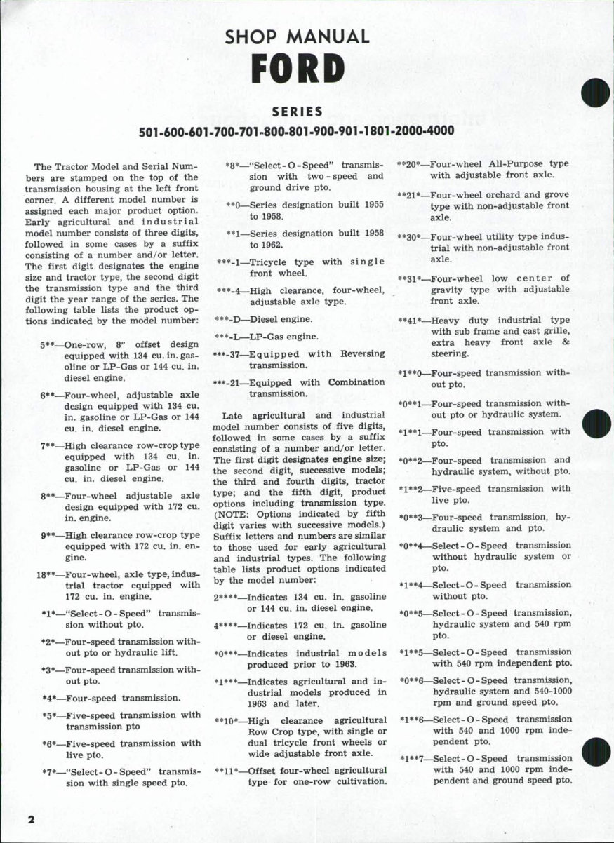
SHOP MANUAL
FORD
SERIES
501 -600-601-700-701 -800-801 -900-901 -1801 -2000-4000
The Tractor Model and Serial Num-
bers are stamped on the top of the
transmission housing at the left front
corner. A different model number is
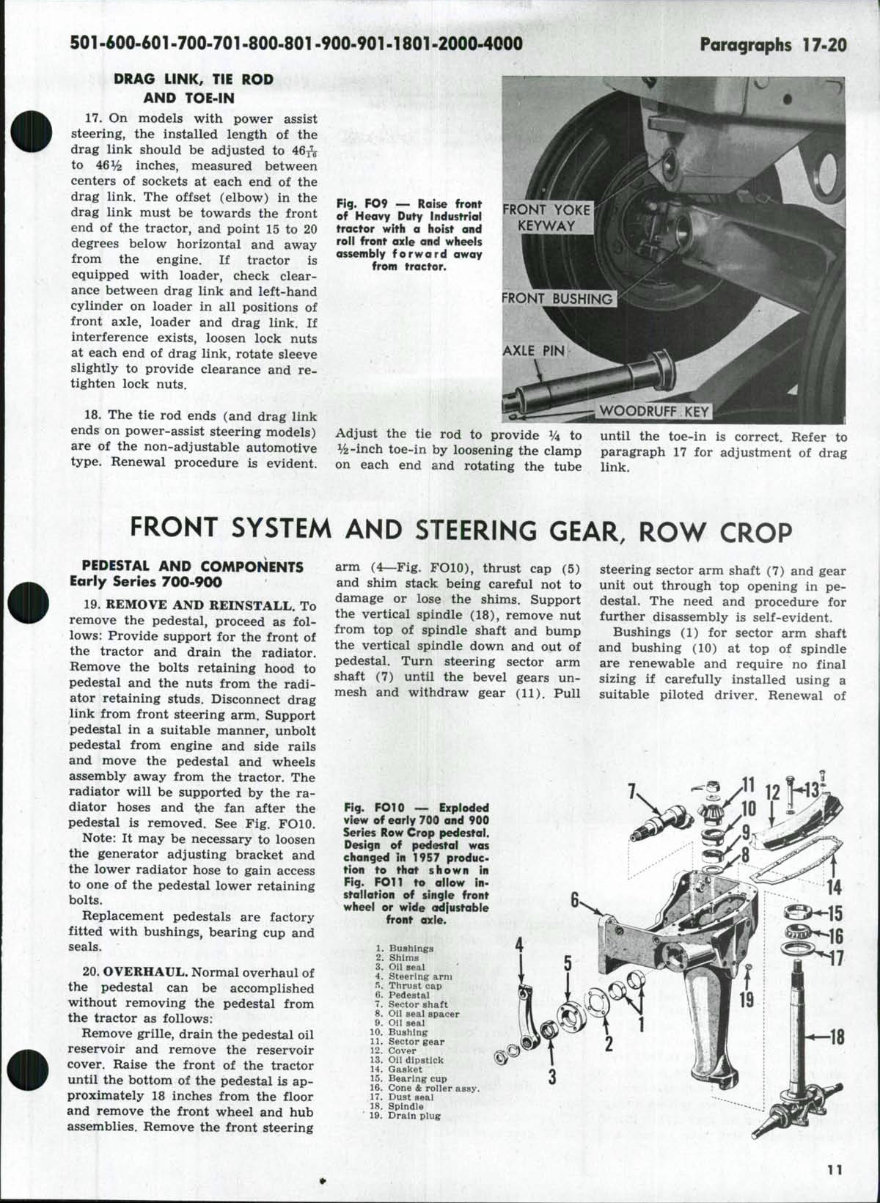
assigned each major product option.
Early agricultural and i n d u s t r i a l
model number consists of three digits,
followed in some cases by a suffix
consisting of a number and/or letter.
The first digit designates the engine
size and tractor type, the second digit
the transmission type and the third
digit the year range of the series. The
following table lists the product op-
tions indicated by the model number:
5**—One-row, 8" offset design
equipped with 134 cu. in. gas-
oline or LP-Gas or 144 cu. in.
diesel engine.
§•*—Four-wheel, adjustable axle
design equipped with 134 cu.
in. gasoline or LP-Gas or 144
cu. in. diesel engine.
7**—High clearance row-crop type
equipped with 134 cu. in.
gasoline or LP-Gas or 144
cu. in. diesel engine.
8* •—Four-wheel ad j ustable axle
design equipped with 172 cu.
in. engine.
9**—High clearance row-crop type
equipped with 172 cu. in. en-
gine.
l^**—Four-wheel, axle type, indus-
trial tractor equipped with
172 cu. in. engine.
•l*_"Select-O-Speed" transmis-
sion without pto.
•2*—Four-speed transmission with-
out pto or hydraulic lift.
•3*—Four-speed transmission with-
out pto. / .
*4*—Four-speed transmission.
•5*—Five-speed transmission with
transmission pto
•6*—Five-speed transmission with
live pto.
•7*—"Select- O- Speed" transmis-
sion with single speed pto.
*8*—"Select - O - Speed" transmis-
sion with two - speed and
ground drive pto.
**0—Series designation built 1955
to 1958.
**l_Series designation built 1958
to 1962.
***_!—^Tricycle type with single
front wheel.
***-4—High clearance, four-wheel,
adjustable axle type.
***_!>—^Diesel engine.
***-L—LP-Gas engine,
•**-37—Equipped with Reversing
transmission.
•**_2i—Equipped with Combination
transmission.
Late agricultural and industrial
model number consists of five digits,
followed in some cases by a suffix
consisting of a number and/or letter.
The first digit designates engine size;
the second digit, successive models;
the third and fourth digits, tractor
type; and the fifth digit, product
options including transmission type.
(NOTE: Options indicated by fifth
digit varies with successive models.)
Suffix letters and numbers are similar
to those used for early agricultural
and industrial types. The following
table lists product options indicated
by the model number:
2****—Indicates 134 cu. in. gasoline
or 144 cu. in. diesel engine.
4****—Indicates 172 cu. in. gasoline
or diesel engine.
*0***—Indicates industrial models
produced prior to 1963.
•1***—Indicates agricultural and in-
dustrial models produced in
1963 and later.
**10*—High clearance agricultural
Row Crop type, with single or
dual tricycle front wheels or
wide adjustable front axle.
**11*—Offset four-wheel agricultural
type for one-row cultivation.
**20*—^Four-wheel All-Purpose type
with adjustable front axle.
**2i*—Four-wheel orchard and grove
type with non-adjustable front
axle.
**30*—Four-wheel utility type indus-
trial with non-adjustable front
axle.
**31*—Four-wheel low center of
gravity type with adjustable
front axle.
**41*—Heavy duty industrial type
with sub frame and cast grille,
extra heavy front axle &
steering.
*1**Q—Four-speed transmission with-
out pto.
*0**i—Four-speed transmission with-
out pto or hydraulic system.
*1**1—Four-speed transmission with
pto.
*0**2—Four-speed transmission and
hydraulic system, without pto.
*1**2—Five-speed transmission with
live pto.
•0**3—Four-speed transmission, hy-
draulic system and pto.
*0**4—Select - O - Speed transmission
without hydraulic system or
pto.
*1**4—Select-O- Speed transmission
without pto.
*0**5—Select - O - Speed transmission,
hydraulic system and 540 rpm
pto.
* 1 * *5—Select - O - Speed transmission
with 540 rpm independent pto.
*0**6—Select - O - Speed transmission,
hydraulic system and 540-1000
rpm and ground speed pto,
*1**6—Select- O - Speed transmission
with 540 and 1000 rpm inde-
pendent pto.
* 1 * *7—Select - O - Speed transmission
with 540 and 1000 rpm inde-
pendent and ground speed pto.
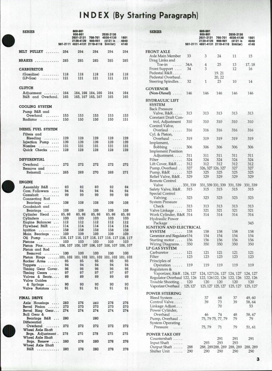
INDEX (By Starting Paragraph)
SERIES 600-601
aOO'BOl 2030-2130
2031-2131 700-701 4030-4130
2120-4120 900-901 (4121 1$
501-2111 4031-4131 2110-4110 Similar)
BELT PULLEY 294 294 294 294
BRAKES 265 285 285 285
CARBURETOR
(Gasoline) 116 118 118 118
(LP-Gas) 121 121 121 121
CLUTCH
Adjustment 184 184. 186 164, 168 164
R&R and Overhaul. 185 165. 167 165. 167 165
COOLING SYSTEM
Pump R&R and
Overhaul 153
Radiator 150
DIESEL FUEL SYSTEM
Filters and
Bleeding 129
Injection Pump 139
Nozzles 131
Quick Checks 126
DIFFERENTIAL
Overhaul 272
Remove and
Reinstall 265
ENGINE
Assembly R&R 83
Cam Followers 94
Camshaft 99
Connecting Rod
Bearings 106
Crankshaft and
Bearings 109
CyUnder Head 85.88
Cylinders 103
Engine Balancer . . . 112
Flywheel R&R 114
Ignition 156
Main Bearings 109
Oil Pump 118,117
Pistons 103
Piston Pins 108, 107
Piston and Rod
Removal 100
Piston Rings 101,102
Rocker Arms 95
Tappets 94
Timing Gear Cover. 96
^ming Gears 97
Valves & Seats 89
Valve Guides
& Springs 90
Valve Rotators 91
FINAL DRIVE
Axle Housings 263
Bevel Pinion 273
Bevel Ring Gear... 274
Bull Gear &
Bearings R&R ... 280
Differential
Overhaul 272
Wheel Axle Shaft
Brgs. Adjustment . 278
Wheel Axle Shaft
Brgs. Renew 280
Wheel Axle Shaft
R&R 280
153
150
129
139
131
128
272
289
82
94
99
108
109
65.86
103
112
114
156
109
153
150
129
139
131
126
272
270
83
94
99
106
109
85,86
103
112
114
158
109
153
150
129
139
131
128
272
269
82
94
99
106
109
85.86
103
112
114
158
109
1801
4040
4140
294
285
118
121
164
165
153
151
129
139
131
126
272
271
84
94
99
106
109
85.86
103
112
114
156
109
116. 117 116.117 116.117 116,117
103 103 103 103
108. 107 106, 107 106. 107 106.107
100 100 100 100
101. 102 101, 102 101. 102 101, 102
95 95 95 95
94 94 94 94
96 96 96 96
97 97 97 97
69 69 89 69
90
91
276
273
274
272
275
276
276
90
91
2H3
273
274
280
272
276
260
280
90
91
276
273
274
272
275
276
276
90
91
276
273
274
272
275
276
276
SERIES
FRONT AXLE
Axle Main Member
Drag Links and
Toe-in
Front Support ....
Pedestal R&R
Pedestal Overhaul.
Steering Spindles..
GOVERNOR
(Non-Diesel)
600-601
600-601 2030-2130
2031-2131 700-701 4030-4130 1601
2120-4120 900-901 (4121 Is 4040
901-2111 4031-4131 2110^110 Simirar) 4140
33
34A
34
32
146 146
24
25
19.21
20,22
23
146
11
13
12
10
146
HYDRAULIC LIFT
SYSTEM
Back Pressure
Valve, R&R 313
Constant Draft Con-
trol Adjustment 310
Control Valve,
Overlaul 316
Cyl. & Piston,
Overhaul 319
Implement
Bobbing 306
Implement Position
Adjustment 311
Filter 324
Lift Cover, R&R... 312
Pump, Overhaul .. 327
Pump, R&R 325
Relief Valve, R&R . 329
Remote Control
Valve 331,339
Safety Valve, R&R. 315
Special Control
Valving 323
System Pressure
Check 313
Valve Linkage 321
Work Cylinder, R&R 314
Hydraulic Power
Package
IGNITION AND ELECTRICAL
SYSTEM 158
Generator and Regulatorl54
Starting motor .... 156
Wiring Diagrams.. 350
LF GAS SYSTEM
Carburetor 121
Filter 123
Principles of
Operation 119
Regulators &
Vaporizer, R&R . 124,127
Regulator Overhaul 122,126
Trouble Shooting.. 120
Vaporizer Overhaul . 125,127
FOWER STEERING
Bleed System
Control Valve
Linkage Adjust ....
Power Cylinder,
Overhaul
Pump, Overhaul ..
System Operating
Pressure
FOWER TAKE OFF
Countershaft
Input Shaft
Output Shaft 288
Shifter Unit 290
313 313
310 310
316 316
319 319
306 306
311
324
312
311
324
312
326,327 326,327
325 325
329 329
331,339 331,339
315 315
323 323
313
321
314
158
154
156
350
121
123
313
321
314
158
154
156
350
121
123
119 119
124,127124,127
122,126122,126
120 120
125,127 125,127
37
39
68
73
70
319
306
311
324
312
327
325
329
331,339
315
323
313
321
314
158
154
156
350
121
123
119
124,127
122,126
120
125,127
37
39
46 74
75, 79 75, 77, 79
75,79 71
48
79
79
15
17,18
16
14
146
313
310
316
313
310
316
291 291
293 293 293
288, 289288, 289 288, 289
290 290 290
319
306
311
324
312
327
325
329
331,339
315
323
313
321
314
345
158
154
156
350
121
123
119
124,127
122,126
120
125,127
49,60
58,64
53
58,67
79
51,61
291
288,289
290
iNDEX (Continued)
SERIES 600-601
^"**^^ 800-801 2030-2130
2031-2131 700-701 4030-4130 1801
2120-4120 900-901 (4121 is 4040
501-2111 4031-4131 2110-4110 Similar) 4140
REAR AXLE
Bearing. Renewal... 280 276 280 276 276
Shaft, R&R 280 276 280 276 276
STEERING GEAR
Adjustment 35 5,39 26 39 53.62
Overhaul 36 9.44 31 44 54.65
Remove and
Reinstall 36 8.40 30 40 54,63
TRANSMISSION
(Four-Speed)
Assembly R&R .... 185 185 185 185 185
Clutch Shaft 189 189 189 189 189
Countershaft 192 192 192 192 192
Mainshatt 190 190 190 190 190
PTO Shifter &
Brg. Support .... 194, 290 194, 290 194, 290 194. 290 194. 290
Reverse Gear 193 193 193 193 193
Shifter Rails and
Fork 187 187 187 187 187
TRANSMISSION
(Five-Speed) ^
Assembly R&R .... '. 195 195 195
Clutch Shaft 200 200 200
Countershaft V ; 204 204 204
Main Drive Gear
& Shaft 201 201 201
SERIES
Reverse Gear
Shifter Rails & Forks
TRANSMISSION
(Combination)
Assembly R&R
Cluster Shaft .
Clutch Shaft .
Drive Shaft ..
Shifter Rails & Forks
TRANSMISSION
(Reversing)
Assembly R&R ...
Overhaul
"SELECTO-SPEED"
TRANSMISSION
Adjustment
Assembly R&R ...
Control Valve R&R
Operation
Overhaul
Pump R&R
PTO System
Trouble Shooting .
Oil Filter
600-601
800-801
2031-2131
2120-4120
501-2111 4031-4131
SPEED (Cont.)
199
! 197
170
177
173
174
J 171
178
179
223
EO to to
!-• CO CO
CO CO •<]
232
241
259
229
233
700-701
900-901
2110-4110
199
197
170
111
173
174
171
178
179
223
to to to
h^ CO CO
CO CO -<]
232
241
259
229
233
2030-2130
4030-4130
(4121 is
Similar)
199
197
170
177
173
174
171
178
179
223
237
238
218
232
241
259
229
233
1801
4040
4140
170
177
173
174
171
178
179
237
238
21R
232
241
259
229
233
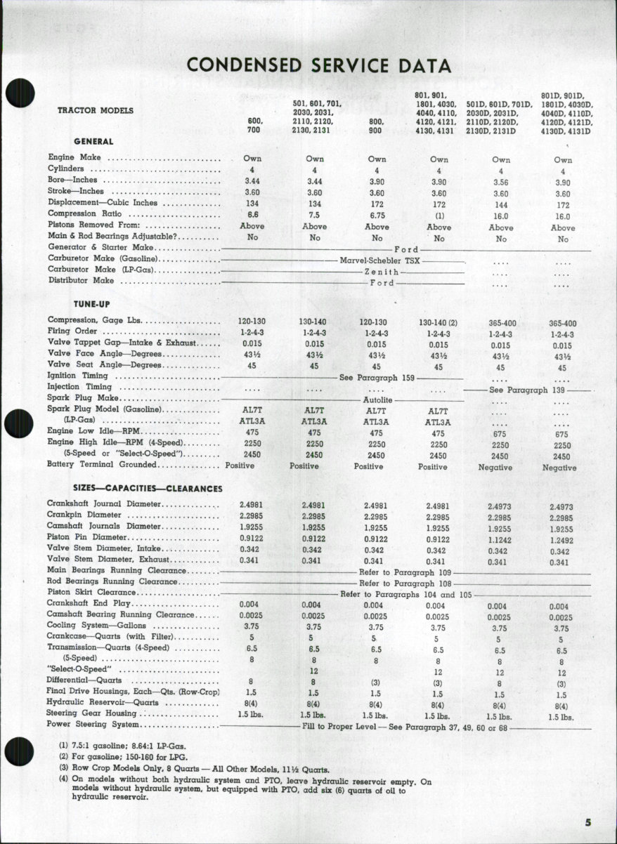
CONDENSED SERVICE DATA
801,901, 801D,901D,
501,601,701, 1801.4030, 501D, 601D, 701D, 1801D,4030D,
TRACTOR MODELS 2030,2031, 4040,4110, 2030D, 2031D, 4040D, 4110D,
600, 2110,2120, 800, 4120,4121, 2110D, 2120D, 4120D,4121D,
700 2130,2131 900 4130,4131 2130D,2131D 4130D,4131D
GENERAL
Engine Make Own Own Own Own Own Own
Cylinders 4 4 4 4 4 4
Bore—Inches 3.44 3.44 3.90 3.90 3.56 3.90
Stroke—Inches 3.60 3.60 3.60 3.60 3.60 3.60
Displacement—Cubic Inches 134 134 172 172 144 172
Compression Ratio 6.6 7.5 6.75 (1) 16.0 16.0
Pistons Removed From: Above Above Above Above Above Above
Main & Rod Bearings Adjustable? No No No No No No
Generator & Starter Make Ford —
Carburetor Make (Gasoline) Marvel-Schebler TSX .
Carburetor Make (LP-Gas) -~ Zenith
Distributor Make .— Ford
TUNE-UP
Compression, Gage Lbs 120-130 130-140 120-130 130-140 (2) 365-400 365-400
Firing Order 1-2-4-3 1-24.3 1-2-4-3 1-2-4-3 1-2-4-3 1-2-4-3
Valve Tappet Gap—Intake & Exhaust 0.015 0.015 0.015 0.015 0.015 0.015
Valve Face Angle—Degrees 43V4 43^2 43V4 43V4 43Vi 43Vi
Valve Seat Angle—Degrees 45 45 45 45 45 45
Ignition Timing See Paragraph 159
Injection Timing .... .... See Paragraph 139
Spark Plug Make . Autolite - •
Spark Plug Model (Gasoline) AL7T AL7T AL7T AL7T
fLP-Gas) ATL3A ATL3A ATL3A ATL3A
Engine Low Idle—RPM 475 475 475 475 675 675
Engine High Idle—RPM (4-Speed) 2250 2250 2250 2250 2250 2250
(5-Speed or "Select-O-Speed") 2450 2450 2450 2450 2450 2450
Battery Terminal Grounded Positive Positive Positive Positive Negative Negative
SIZES^CAPACITIES—CLEARANCES
Crankshaft Journal Diameter 2.4981 2.4981 2.4981 2.4981 2.4973 2.4973
Crankpin Diameter 2.2985 2.2985 2.2985 2.2985 2.2985 2.2985
Camshaft Journals Diameter 1.9255 1.9255 1.9255 1.9255 1.9255 1.9255
Piston Pin Diameter 0.9122 0.9122 0.9122 0.9122 1.1242 1.2492
Valve Stem Diameter. Intake 0.342 0.342 0.342 0.342 0.342 0.342
Valve Stem Diameter, Exhaust 0.341 0.341 0.341 0.341 0.341 0.341
Main Bearings Running Clearance Refer to Paragraph 109
Rod Bearings Running Clearance Refer to Paragraph 108
Piston Skirt Clearance — Refer to Paragraphs 104 and 105
Crankshaft End Play 0.004 0.004 0.004 0.004 0.004 0.004
Camshaft Bearing Running Clearance 0.0025 0.0025 0.0025 0.0025 0.0025 0.0025
Cooling System—Gallons 3.75 3.75 3.75 3.75 3.75 3.75
Crankcase—Quarts {with Filter) 5 5 S 5 5 5
Transmission—Quarts (4-Speed) 6.5 6.5 6.5 6.5 6.5 6.5
(5-Speed) 8 8 8 8 8 8
"Select-O-Speed" 12 12 12 12
Differential—Quarts 8 8 (3) (3) 8 (3)
Final Drive Housings. Each—Qts. (Row-Crop] 1.5 1.5 I.5 1.5 1.5 15
Hydraulic Reservoir—Quarts 8(4) 8(4) 8(4) 8(4) 8(4) 8(4)
Steering Gear Housing .: 1.5 lbs. 1.5 lbs. 1.5 lbs. 1.5 lbs. 1.5 lbs. 1.5 lbs.
Power Steering System FiU to Proper Level — See Paragraph 37, 49, 60 or 68
(1) 7.5:1 gasoline; 8.64:1 LP-Gas.
(2) For gasoline; 150-160 for LPG.
(3) Row Crop Models Only, 8 Quarts — All Other Models, llV^ Quarts.
(4) On models without both hydraulic system and PTO, leave hydraulic reservoir empty. On
models without hydrauUc system, but equipped with PTO, add six (6) quarts of oU to
hydraulic reservoir.
Paragraphs 1-4
FORD
FRONT SYSTEM AND MANUAL STEERING
ALL-PURPOSE TYPE
(LCG Type Front System and Manual Steering are Similar)
11 12
SPINDLE BUSHINGS
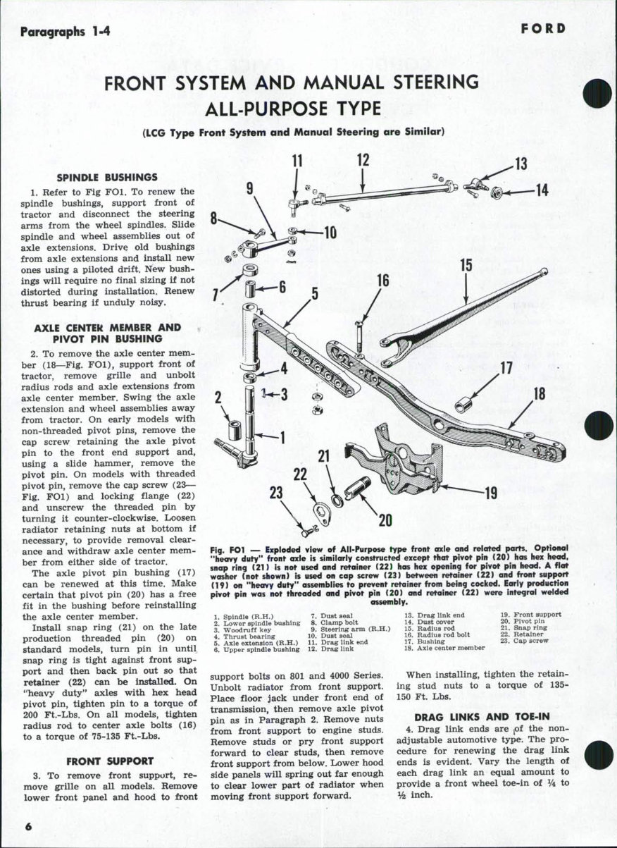
1. Refer to Fig FOl. To renew the
spindle bushings, support front of
tractor and disconnect the steering
arms from the wheel spindles. Slide
spindle and wheel assemblies out of
axle extensions. Drive old busihings
from axle extensions and install new
ones using a piloted drift. New bush-
ings will require no final sizing if not
distorted during installation. Renew
thrust bearing if unduly noisy,
AXLE CENTEk MEMBER AND
PIVOT PIN BUSHING
2. To remove the axle center mem-
ber (18—Fig. FOl), support front of
tractor, remove grille and unbolt
radius rods and axle extensions from
axle center member. Swing the axle
extension and wheel assemblies away
from tractor. On early models with
non-threaded pivot pins, remove the
cap screw retaining the axle pivot
pin to the front end support and,
using a slide hammer, remove the
pivot pin. On models with threaded
pivot pin, remove the cap screw (23—
Fig. FOl) and locking flange (22)
and unscrew the threaded pin by
turning it counter-clockwise. Loosen
radiator retaining nuts at bottom if
necessary, to provide removal clear-
ance and withdraw axle center mem-
ber from either side of tractor.
The axle pivot pin bushing (17)
can be renewed at this time. Make
certain that pivot pin (20) has a free
fit in the bushing before reinstalling
the axle center member.
Install snap ring (21) on the late
production threaded pin (20) on
standard models, turn pin in until
snap ring is tight against front sup-
port and then back pin out so that
retainer (22) can be installed. On
''heavy duty" axles with hex head
pivot pin, tighten pin to a torque of
200 Ft.-Lbs. On all models, tigjiten
radius rod to center axle bolts (16)
to a torque of 75-135 Ft.-Lbs.
FRONT SUPPORT
3. To remove front support, re-
move grille on all models. Remove
lower front panel and hood to front
14
19
20
Fig. FOl — Exploded view of All-Purpose type front oxie and rejated ports. Optionol
"heovy duty" front axle is similarly constructed except that pivot pin (20) has hex heod,
snop ring (21) is not used and retainer (22) has hex opening for pivot pin head. A flot
washer (not shown) is used on cop screw (23) between retainer (22) and front support
(19) on "heavy duty" assemblies to prevent retainer from being cocked. Early production
pivot pin was not threaded and pivot pin (20) and retainer (22) were integral welded
assembly.
1. Spindle (R.H.)
2. Lower spindle bushing
3. Woodruff key
4. Thrust bearing
5. Axle extension (R.H.)
7. Dust seal
8. Clamp boit
9. Steering arm (R.H.)
10. Dust seal
11. Drag link end
6. Upper spindl© bushing 12. Drag link
support bolts on 801 and 4000 Series.
Unbolt radiator from front support.
Place floor jack under front end of
transmission, then remove axle pivot
pin as in Paragraph 2. Remove nuts
from front support to engine studs.
Remove studs or pry front support
forward to clear studs, then remove
front support from below. Lower hood
side panels will spring out far enough
to clear lower part of radiator when
moving front support forward.
13. Drag link end
14. Dust cover
15. Radius rod
16. Radius rod bolt
17. Bushing
18. Axle center member
19. Front support
20. Pivot pin
21. Snap ring
22. Retainer
23. Cap screw
When installing, tighten the retain-
ing stud nuts to a torque of 135-
150 Ft. Lbs.
DRAG LINKS AND TOE-IN
4. Drag link ends are pt the non-
adjustable automotive type. The pro-
cedure for renewing the drag link
ends is evident. Vary the length of
each drag link an equal amount to
provide a front wheel toe-in of V4 to
% inch.
501-600-601-700-701-800-801 -900-901 -1801 -2000-4000 Paragraphs 5-8
30
31
1. Lock nuts
2. Flat washers
3. Packing
4. End covers
5. Bushings
6. "O" ring
8. Adjusting screw
9. Sector gear (double)
9A. Sector g&ar (single)
10. Pitman arms
11. Dustseais
12. Packing retainera
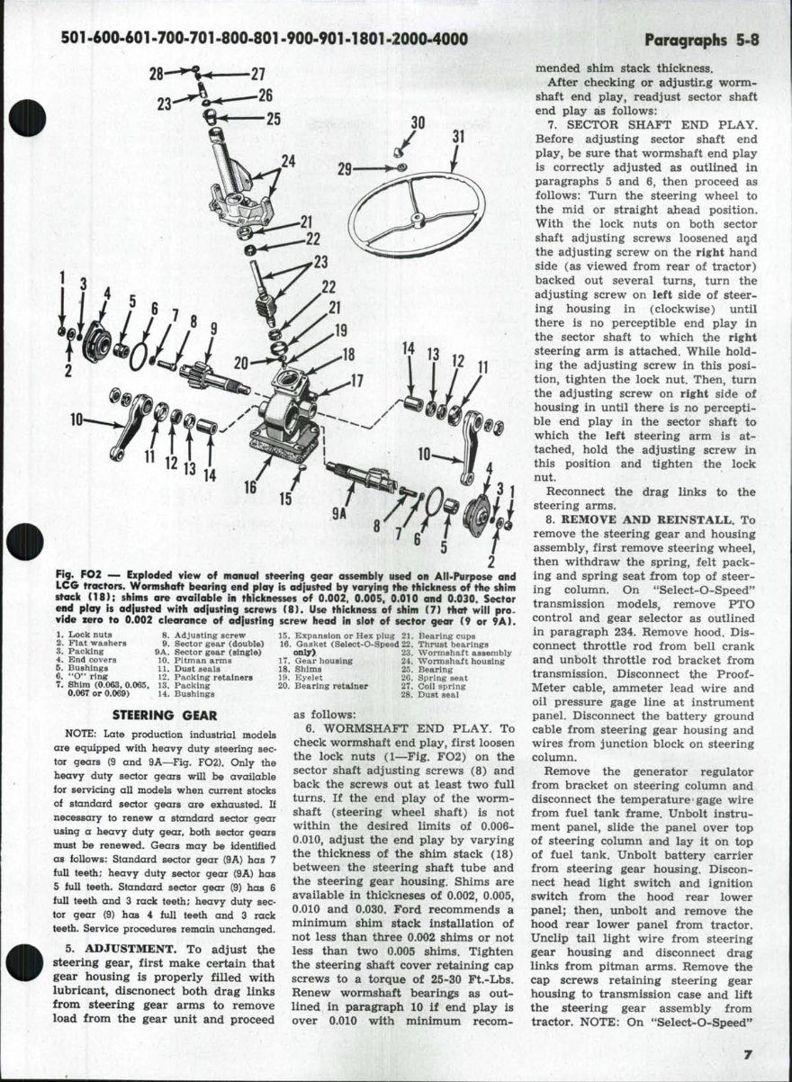
Fig. FO2 — Exploded view of manual steering gear assembly used on All-Purpose and
LCG tractors. Wormshaft bearing end play is adjusted by varying the thickness of the shim
stack (18); shims are available in thicknesses of 0.002. 0.005. 0.010 and 0.030. Sector
end play is adiusted with adfusting screws ( 8 ) . Use thickness of shim (7) that will pro.
vide zero to 0.002 clearance of adjusting screw head in slot of sector gear (9 or 9A).
15. Expansion or Hex piug 21. Bearing cups
16. Gasket (Select-0-Speed 22. Thrust bearings
(MLly). 23. Wormshaft assembly
17. Gear housing 24. Wormshaft housing
18. Shims 25. Bearing
19. Eyelet 26. Spring seat
20. Bearing retainer 27. Coil spring
28. Dust seai
as follows:
6. WORMSHAFT END PLAY. To
check wormshaft end play, first loosen
the lock nuts (1—Fig. FO2) on the
sector shaft adjusting screws (8) and
back the screws out at least two full
turns. If the end play of the worm-
shaft (steering wheel shaft) is not
within the desired limits of 0,006-
0.010, adjust the end play by varying
the thickness of the shim stack (18)
between the steering shaft tube and
the steering gear housing. Shims are
available in thickneses of 0.002, 0.005,
0.010 and 0.030. Ford recommends a
minimum shim stack installation of
not less than three 0.002 shims or not
less than two 0.005 shims. Tighten
the steering sJiaft cover retaining cap
screws to a torque of 25-30 Ft.-Lbs.
Renew wormshaft bearings as out-
lined in paragraph 10 if end play is
over 0.010 with minimum recom-
7. Shim (0.063, 0.065, 13. Packing
0.067 or 0.069) 14. Bushings
STEERING GEAR
NOTE: Late production industrial models
are equipped with heavy duty steering sec-
tor gears (9 and 9A—Fig. FO2). Only the
heavy duty sector gears will be available
for servicing all modeb when current stocks
of standard sector gears are exhausted. If
necessary to renew a standard sector gear
using a heavy duty gear, both sector gears
must be renewed. Gears may be identified
as follows: Standard sector gear (9A) has 7
full teeth; heavy duty sector gear {9A) has
5 full teeth. Standard sector gear (9) has 6
full teeth and 3 rack teeth; heavy duty sec-
tor gear (9) has 4 full teeth and 3 rack
teeth. Service procedures remain unchanged.
5. ADJUSTMENT. To adjust t;he
steering gear, first make certain that
gear housing is properly filled with
lubricant, discnonect both drag links
from steering gear arms to remove
load from the gear unit and proceed
mended shim stack thickness.
After checking or adjusting worm-
shaft end play, readjust sector shaft
end play as follows:
7. SECTOR SHAFT END PLAY.
Before adjusting sector shaft end
play, be sure that wormshaft end play
is correctly adjusted as outlined in
paragraphs 5 and 6, then proceed as
follows: Turn the steering wheel to
the mid or straight ahead position.
With the lock nuts on both sector
shaft adjusting screws loosened aijd
the adjusting screw on the right hand
side (as viewed from rear of tractor)
backed out several turns, turn the
adjusting screw on left side of steer-
ing housing in (clockwise) until
there is no perceptible end play in
the sector shaft to which the right
steering arm is attached. While hold-
ing the adjusting screw in this posi-
tion, tighten the lock nut. Then, turn
the adjusting screw on right side of
housing in until there is no percepti-
ble end play in the sector shaft to
which the left steering arm is at-
tached, hold the adjusting screw in
this position and tighten the lock
nut.
Reconnect the drag links to the
steering arms.
8. REMOVE AND REINSTALL. To
remove the steering gear and housing
assembly, first remove steering wheel,
then withdraw the spring, felt pack-
ing and spring seat from top of steer-
ing column. On **Select-O-Speed"
transmission models, remove PTO
control and gear selector as outlined
in paragraph 234. Remove hood. Dis-
connect throttle rod from bell crank
and unbolt throttle rod bracket from
transmission. Disconnect the Proof-
Meter cable, ammeter lead wire and
oil pressure gage line at instrument
panel. Disconnect the battery ground
cable from steering gear housing and
wires from junction block on steering
column.
Remove the generator regulator
from bracket on steering column and
disconnect the temperature gage wire
from fuel tank frame. Unbolt instru-
ment panel, slide the panel over top
of steering column and lay it on top
of fuel tank. Unbolt battery carrier
from steering gear housing. Discon-
nect head light switch and ignition
switch from the hood rear lower
panel; then, unbolt and remove the
hood rear lower panel from tractor.
Unclip tail light wire from steering
gear housing and disconnect drag
links from pitman arms. Remove the
cap screws retaining steering gear
housing to transmission case and lift
the steering gear assembly from
tractor. NOTE: On *'Select-O-Speed"
Paragraphs 9-13
transmission models, a gasket is used
between steering gear and transmis-
sion housings. Gasket should be left
in place or opening in transmission
covered when steering gear housing
is removed. Be sure that gasket is in
good condition before reinstalling
steering gear assembly.
9. OVERHAUL. Major overhaul of
the steering gear unit necessitates the
removal of the unit from tractor as
outlined in paragraph 8. Remove the
pitman arm retaining nuts and pull
pitman arms from sector shafts. Un-
bolt the sector shaft side covers and
remove the adjusting screw lock nuts
(1—Fig. FO2), Using a screwdriver,
turn the adjusting screws in and re-
move the side covers and sector
shafts. Unbolt steering housing upper
cover from housing and remove cover,
shaft and ball nut assembly. Do not
disassemble the ball nut and steering
shaft assembly (23) as component re-
placement parts are not available. If
the steering shaft and/or ball nut are
damaged, renew the complete assem-
bly. The need and procedure for
further disassembly and/or overhaul
is self-evident.
The renewable bushings in steering
gear covers have a bore diameter of
1.1255-1.1260; bushings in housing
have a bore diameter of 1.245-1.250.
S,hims (7) on the adjusting screws
(8) are available in thicknesses of
0.063, 0.065, 0.067 and 0.069. When
reassembling, use a shim that will
provide zero to 0.002 clearance be-
tween adjusting screw head and slot
in sector shafts.
When reassembling, center the ball
nut on wormshaft and insert shaft in
housing. Bolt the housing upper cover
assembly in position, using the neces-
sary number of shims (18) to provide
an end play of 0.006-0.010 of worm-
shaft in bearing. Minimum shim stack
should be three 0.002 shims or two
0.005 shims. If end play is more than
0.010 with minimum recommended
thickness of shims, renew the worm-
FORD
shaft bearings. Shims (18) are avail-
able in thicknesses of 0.002, 0.005,
0.010 and 0.030. Tighten the cover
cap screws to a torque of 25-30 Ft.-
Lbs. Assemble the sectors and their
adjusting screws (8) to their covers.
Hold the left sector shaft (the one
with the greater number of teeth)
and side cover assembly with the
block tooth up, and install the sector
so that middle tooth on sector meshes
with middle groove on the ball nut
rack. Install the right sector shaft,
meshing the fourth tooth with the
fourth groove of the left sector shaft.
Tighten the side cover cap screws to
a torque of 25-30 Ft.-Lbs. and install
the adjusting screw lock nuts.
Turn steering gear to its mid or
straight ahead position and install
pitman arms.
When installation is complete, fill
gear housing with lubricant and ad-
just the sector shaft end play as out-
lined in paragraph 7. Reconnect the
drag link.
FRONT SYSTEM, UTILITY INDUSTRIAL TYPE
(Front System of Grove Type is Similar. Utiiity Industrial and Grove Types
Are Equipped With Power Steering Only.)
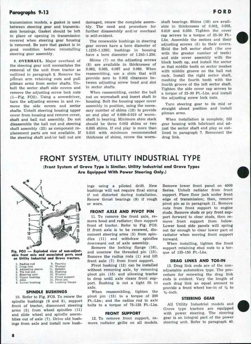
Fig. FO3 — Exploded view of non-adjust-
able front axle and associated pcrts used
on Utility Industrial and Grove tractors.
1. Badius rod
2. Drag link
3. Adjusting sleeve
4. Tie rod end
5. Steering arm
6. Upper bushing
7. Axle
8. Lower bushing
9. Bearing
10. Washer
11. Spindle
12. Bushing
13. Washer
14. Front support
15. Pivot pin
16. Locking fiange
SPINDLE BUSHINGS
10. Refer to Fig. FO3. To renew the
spindle bushings (6 and 8), support
front of tractor, disconnect steering
arms (5) from wheel spindles (11)
and slide wheel and spindle assem-
blies out of axle (7). Drive old bush-
ings from axle and install new busli-
ings using a piloted drift. New
bushings will not require final sizing
if not distorted during installation.
Renew thrust bearings (9) if rough
or worn,
FRONT AXLE AND PIVOT PIN
11. To remove the front axle, re-
move hood and radiator; then support
front of tractor. Refer to Fig. FO3.
If front axle is to be renewed, dis-
connect steering arms (5) from spin-
dles (11) and withdraw spindles
downward out of axle assembly.
Remove the locking flange (16),
and unscrew the threaded pin (15).
Remove the radius rods (1) and lift
front axle (7) from front support.
Pivot bushing (12) can be installed
without removing axle, by removing
pivot pin (15) and allowing tractor
to drop until axle clears front sup-
port. Bushing is not a tight fit in
axle.
When reassembling, tighten the
pivot pin (15) to a torque of 200
Ft.-Lbs.; and the radius rod to axle
bolts to a torque of 75-135 Ft.-Lbs.
FRONT SUPPORT
12. To remove front support, re-
move radiator grille on all models.
Remove lower front panel on 4000
Series. Unbolt radiator from front
support. Place floor jack under front
edge of transmission; then, remove
pivot pin as in paragraph 11. Remove
nuts from front support to engine
studs. Remove studs or pry front sup-
port forward to clear studs, then re-
move front support from below.
Lower hood side panels will spring
out far enough to clear lower part of
radiator when moving front support
forward.
When installing, tighten the front
support retaining stud nuts to a tor-
que of 135-150 Ft.-Lbs.
DRAG LINKS AND TOE-IN
13. Drag link ends are of the non-
adjustable automotive type. The pro-
cedure for renewing the drag link
ends is evident. Vary the length of
each drag link an equal amount to
provide a front wheel toe-in of V^ to
STEERING GEAR
All Utility Industrial models and
Grove type tractors are equipped
with power steering. The steering
gear is an integral part of the power
steering unit. Refer to paragraph 40.
8

501-600-601-700-701-800-801-900-90M 801 -2000-4000 Parographs 14-15
FRONT SYSTEM, H. D. INDUSTRIAL TYPE
14
19
18-
Fig. F04 — Expioded view (from rear) of front cnle assembly used on early Heavy Duty
Industrial tractor with full power steering.
1. Left steering amn
2. Spindle
3. Spindle buahlng
4. SplndTepln
6. Pin seal
6. Tapered re tain lag pin
7. Axle nnember
8. Pivot pin
9. Woodruff key
10. Thrust washer
11. Rear pivot bushing
12. Front pivot bushing
13. Thrust bearing
14. Tab washer
15. Jam nut
16. Tie rod end
17. Tie rod
18. Tie rod end
19. Right steering
arm
STEERING GEAR
18
SPINDLE BUSHINGS
All Models
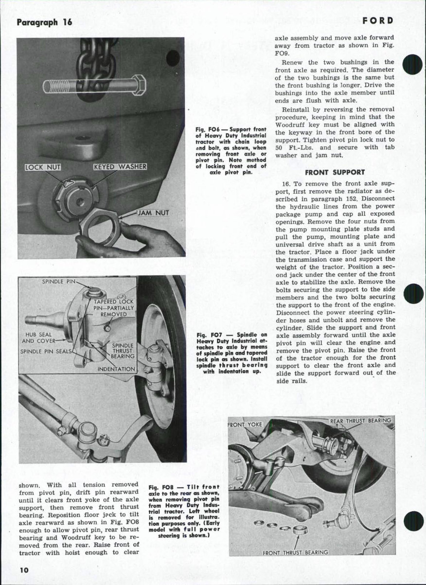
14. To renew spindle bushings, jack
up the front axle and remove wheel
and hub assembly. Cut lock wire or
bend locking tabs down and unbolt
steering arm from spindle. Tie-rod
and/or power steering cylinder need
not be disconnected from steering
arm. Remove nut and lock washer
from tapered lock pin (6—Fig. FO4
or Fig. FO5) and drive out tapered
pin. Drive spindle pin upward
enough to relieve the pressure on
upper spindle pin seal, remove upper
seal, then drive spindle pin down-
ward out of axle.
Spindle bushings are pre-sized and
will require no final sizing if care-
fully installed. Renew thrust bearing
if unduly noisy. Thrust bearing is
installed with the indentation up as
shown in Fig. FO7. The detent in the
spindle pin is off center. Install spin-
dle pin with stamped "T** mark facing
upward so that spindle pin will be
properly located in axle. Torque steer-
ing arm bolts to 100 Ft.-Lbs., and se-
cure with safety wire or locking tabs.
FRONT AXLE AND PIVOT PIN
15. To remove the front axle (7—
Fig. FO4 or 7A—Fig. FO5), first dis-
connect the tie rod from either steer-
ing arm and swing tie rod rearward.
Disconnect power cylinder pressure
and return lines at cylinder; then,
disconnect the power cylinder from
the axle and lower the cylinder as-
sembly to the floor. Remove the radi-
ator grille door, pass a chain loop
through hole of front axle support
and secure chain with a bolt or short
rod as shown in Fig. FO6. Attach a
hoist to chain and tighten enough to
take up slack. Place a rolling floor
jack under center of front axle and
raise jack just enough to take the
axle weight off of pivot pin. Straight-
en tabs on keyed lock washer at front
end of pivot pin and remove jam
nut, keyed washer and lock nut as
Fig. FO5 » Expioded view of iate production Heavy Duty Industriol axle assembiy with
drag iink (power assist) steering. View is from front of unit.
lA.
2.
3.
4.
5.
6.
7A.
8.
9.
10.
11.
12.
13.
14.
15.
Left steering arm
Spindles
Spindle bushings
Spindle pins
Spindle pin seals
16.
17.
18.
19.
20.
Tapered retaining pins 21.
Front axle
Pivot pin
Woodruff key
Thrust washer:
Rear pivot bushing
Front pivot biishlng
Thrust spacer
Tab washer
Jam nuts
22.
23.
24.
25.
26.
27.
28.
29.
Tie rod end
Tie rod
Tie rod end
Right steering ar
Dust cover
Thrust bearings
Power steering
cylinder
Dust cover
Retainer
Drag link end
Lock nut
Drag link
Lock nut
Drag link end
Paragraph 16
FORD
Fig. FO6 — Support front
of Heavy Duty Industrial
tractor with chain loop
and bolt, as shown, when
removing front axle or
pivot pin. Note method
of locking front end of
axle pivot pin.
SPINDLE PIN
/
/
"^^^ ' WltliMi 1
HUB SEAL «
AND COVER—*^i
/
SPINDLE PIN SEALSC
7
1/
LA
fm
^1
^^1^ ~ ''
nrAPEREDTdCK
PIN-PARTIALLY
- REMOVED
SC^ SPINDLE
N^ THRUST
INDENTATION
Fig. FO7 ~ Spindle on
Heavy Duty Industrial ot-
toches to axle by means
of spindle pin and tapered
lock pin as shown. Install
spindle thrust bearing
with indentation up.
axle assembly and move axle forward
away from tractor as shown in Fig.
FO9.
Renew the two bushings in the
front axle as required. The diameter
of the two bushings is the same but
the front bushing is longer. Drive the
bushings into the axle member until
ends are flush with axle.
Reinstall by reversing the removal
procedure, keeping in mind that the
Woodruff key must be aligned with
the keyway in the front bore of the
support. Tighten pivot pin lock nut to
50 Ft.-Lbs. and secure with tab
washer and jam nut.
FRONT SUPPORT
16. To remove the front axle sup-
port, first remove the radiator as de-
scribed in paragraph 152. Disconnect
the hydraulic lines from the power
package pump and cap all exposed
openings. Remove the four nuts from
the pump mounting plate studs and
pull the pump, mounting plate and
universal drive shaft as a unit from
the tractor. Place a floor jack under
the transmission case and support the
weight of the tractor. Position a sec-
ond jack under the center of the front
axle to stabilize the axle. Remove the
bolts securing the support to the side
members and the two bolts securing
the support to the front of the engine.
Disconnect the power steering cylin-
der hoses and unbolt and remove the
cylinder. Slide the support and front
axle assembly forward until the axle
pivot pin will clear the engine and
remove the pivot pin. Raise the front
of the tractor enough for the front
support to clear the front axle and
slide the support forward out of the
side rails.
FRONT YOKE
shown. With all tension removed
from pivot pin, drift pin rearward
until it clears front yoke of the axle
support, then remove front thrust
bearing. Reposition floor j?ck to tilt
axle rearward as shown in Fig. FO8
enough to allow pivot pin, rear thrust
bearing and Woodruff key to be re-
moved from the rear. Raise front of
tractor with hoist enough to clear
Fig, FO8 — Tilt front
axle to the rear os shown,
when removing pivot pin
from Heavy Duty Indus-
trial troctor. Left wheel
is removed for illustra-
tion purposes only. (Early
model with full power
steering is shown.)
10
501 -600-601 -700-701-800-801 -900-901-1801-2000-4000 Paragraphs 17-20
DRAG LINK, TIE ROD
AND TOE-IN
17. On models with power assist
steering, the installed length of the
drag link should be adjusted to 46^3^
to 46^ inches, measured between
centers of sockets at each end of the
drag link. The offset (elbow) in the
drag link must be towards the front
end of the tractor, and point 15 to 20
degrees below horizontal and away
from the engine. If tractor is
equipped with loader, check clear-
ance between drag link and left-hand
cylinder on loader in all positions of
front axle, loader and drag link. If
interference exists, loosen lock nuts
at each end of drag link, rotate sleeve
slightly to provide clearance and re-
tighten lock nuts.
18. The tie rod ends (and drag link
ends on power-assist steering models)
are of the non-adjustable automotive
type. Renewal procedure is evident.
Fig. FO9 — Roise front
of Heavy Duty industrioi
tractor with a hoist and
roil front axie and wheeis
assembly forward away
from tractor.
Adjust the tie rod to provide V4 to
V^-inch toe-in by loosening the clamp
on each end and rotating the tube
until the toe-in is correct. Refer to
paragraph 17 for adjustment of drag
link.
FRONT SYSTEM AND STEERING GEAR, ROW CROP
PEDESTAL AND COMPONENTS
Early Series 700-900
19. REMOVE AND REINSTALL. To
remove the pedestal, proceed as fol-
lows: Provide support for the front of
the tractor and drain the radiator.
Remove the bolts retaining hood to
pedestal and the nuts from the radi-
ator retaining studs. Disconnect drag
link from front steering arm. Support
pedestal in a suitable manner, unbolt
pedestal from engine and side rails
and move the pedestal and wheels
assembly away from the tractor. The
radiator will be supported by the ra-
diator hoses and the fan after the
pedestal is removed. See Fig. FOIO.
Note: It may be necessary to loosen
the generator adjusting bracket and
the lower radiator hose to gain access
to one of the pedestal lower retaining
bolts.
Replacement pedestals are factory
fitted with bushings, bearing cup and
seals.
20. OVERHAUL. Normal overhaul of
the pedestal can be accomplished
without removing the pedestal from
the tractor as follows:
Remove grille, drain the pedestal oil
reservoir and remove the reservoir
cover. Raise the front of the tractor
until the bottom of the pedestal is ap-
proximately 18 inches from the floor
and remove the front wheel and hub
assemblies. Remove the front steering
arm (4—Fig. FOIO), thrust cap (5)
and shim stack being careful not to
damage or lose the shims. Support
the vertical spindle (18), remove nut
from top of spindle shaft and bump
the vertical spindle down and out of
pedestal. Turn steering sector arm
shaft (7) until the bevel gears un-
mesh and withdraw gear (11). Pull
steering sector arm shaft (7) and gear
unit out through top opening in pe-
destal. The need and procedure for
further disassembly is self-evident.
Bushings (1) for sector arm shaft
and bushing (10) at top of spindle
are renewable and require no final
sizing if carefully installed using a
suitable piloted driver. Renewal of
Fig. FOIO — Exploded
view of eoriy 700 and 900
Series Row Crop pedestai.
Design of pedestal was
changed in 1957 produc
tion to thot shown in
Fig. FOT1 to aliow In-
stallation of single front
wheel or wide adjustable
front axle.
1. Bushings
2. Shims
3. Oil seal
4. Steering arm
5. Thrust cap
6. Pedestal
7. Sector shaft
8. Oil seal spacer
9. Oil seal
10. Bushing
11. Sector gear
12. Cover
13. Oil dipstick
14. Gasket
15. Bearing cup
16. Cone & roller assy.
17. Dust seal
18. Spindle
' 19. Drain plug
n
You're Reading a Preview
What's Included?
Fast Download Speeds
Online & Offline Access
Access PDF Contents & Bookmarks
Full Search Facility
Print one or all pages of your manual
$39.99
Viewed 12 Times Today


Secure transaction
What's Included?
Fast Download Speeds
Online & Offline Access
Access PDF Contents & Bookmarks
Full Search Facility
Print one or all pages of your manual
$39.99
This repair manual is a comprehensive guide for maintaining and repairing the FORD TRACTOR 900, 901, and 1801 models. It provides step-by-step procedures and detailed illustrations to assist both professional mechanics and DIY enthusiasts in performing necessary maintenance and repairs. The manual includes extensive illustrations and exploded views to aid users in understanding the processes involved. The expert text offers complete information on maintenance, tune-up, and repair, helping users save on repair costs by addressing vehicle issues themselves.
- Front System
- Steering System
- Brake System
- Fuel System
- Transmission
- Hydraulic System
- ...and much more...
Gain instant access to this valuable resource and make secure payments using your credit card or PayPal.


