

Ford 2310 2600 2610 3600 3610 4100 4110 4600 4610 4600SU 4610SU Tractor Shop Service Repair Manual
What's Included?
Fast Download Speeds
Online & Offline Access
Access PDF Contents & Bookmarks
Full Search Facility
Print one or all pages of your manual
SHOP MANUAL
FORD
MODELS 2310-2600-2610-3600-3610-4100 (After 1974)-4110-4600-
4610 (Prior To 1984)-4e00SU-4610SU (Prior To 1984)
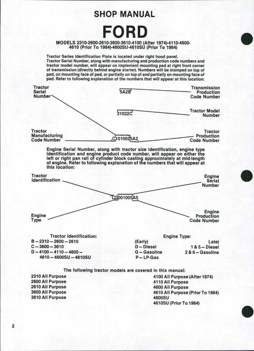
Tractor Series (dentification Piate is iocated under right hood panei.
Tractor Serial Number, aiong with manufacturing and production code numbers and
tractor model number, will appear on implement mounting pad at right front corner
of transmission (directly behind engine starter). Numbers will be stamped on top of
pad, on mounting face of pad, or partially on top of and partially on mounting face of
pad. Refer to foilowing explanation of the numbers that will appear at this location:
Tractor
Serial
Number
Tractor
Manufacturing
Code Number
Transmission
Production
Code Number
Traotor Modei
Number
Tractor
Production
Code Number
Engine Seriai Number, aiong with tractor size identification, engine type
identification and engine product code number, wiii appear on either the
ieft or right pan raii of cyiinder biock casting approximateiy at mid-iength
of engine. Refer to foilowing expianation of the numbers that wiii appear at
this iooation:
Tractor
Identification
Engine
Type
Engine
Seriai
Number
Engine
Production
Code Number
Tractor identification:
B-2310-2600-2610
C-3600-3610
D-4100-4110-4600-
4610-4600SU-4610SU
Engine Type:
(Early) Late)
D-Diesei 1& 5-Diesel
G - Gasoiine 2 & 6 - Gasoiine
P-LPGas
The foliowing traotor modeis are covered in this manuai:
231 OAii Purpose
2600 Aii Purpose
2610 Aii Purpose
3600 Ali Purpose
3610 Aii Purpose
4100 Ali Purpose (After 1974)
4110 Ail Purpose
4600 Aii Purpose
4610 Aii Purpose (Prior To 1984)
4600SU
4610SU (Prior To 1984)
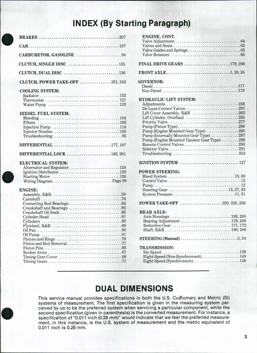
INDEX (By Starting Paragraph)
BRAKES 207
CAB 137
CARBURETOR, GASOLINE 94
CLUTCH, SINGLE DISC 135
CLUTCH, DUAL DISC 136
CLUTCH, POWER TAKE OFF 231,243
COOLING SYSTEM:
Radiator 122
Thermostat 121
Water Pump 123
DIESEL FUEL SYSTEM:
Bleeding 104
Filters 103
Injection Pump 114
Injector Nozzles 105
Troubleshooting 95
DIFFERENTIAL 177,197
DIFFERENTIAL LOCK 183,201
ELECTRICAL SYSTEM:
Alternator and Regulator 124
Ignition Distributor 129
Starting Motor 126
Wiring Diagram Page 99
ENGINE:
Assembly, R&R 59
Camshaft 76
Connecting Rod Bearings 84
Crankshaft and Bearings 85
Crankshaft Oil Seals 86
Cylinder Head 61
Cylinders 80
Flywheel, R&R 89
Oil Pan 90
Oil Pump 91
Pistons and Rings 78
Piston and Rod Removal 77
Piston Pins 83
Rocker Arms 67
Timing Gear Cover 68
Timing Gears 71
ENGINE, CONT.
Valve Adjustment 64
Valves and Seats 62
Valve Guides and Springs 63
Valve Rotators 65
FINAL DRIVE GEARS 179,206
FRONT AXLE 1, 20,35
GOVERNOR:
Diesel 117
Non-Diesel 119
HYDRAULIC LIFT SYSTEM:
Adjustments 258
De-Luxe Control Valves 297
Lift Cover Assembly, R&R ,, 263
Lift Cylinder, Overhaul 265
Priority Valve 277
Pump (Piston Type) 280
Pump (Engine Mounted Gear Type) 285
Pump (Internally Mounted Gear Type) 287
Pump (Engine Mounted Tandem Gear Type) 289
Remote Control Valves .293
Selector Valve 291
Troubleshooting 253
IGNITION SYSTEM .127
POWER STEERING:
Bleed System 10,30
Control Valve 13
Pump 12
SteeringGear 13,27,33
System Pressure 11,31
POWER TAKE-OFF 220,225,236
REAR AXLE:
Axle Housings 193,205
Bearing Adjustment 178, 206
Reduction Gear 171,172
Shaft, R&R 190, 206
STEERING (Manual) 5,24
TRANSMISSION:
Six-Speed 139
Eight-Speed (Non-Synchromesh) 149
Eight-Speed (Synchromesh) 158
DUAL DIMENSIONS
This service manuai provides specifications in both the U.S. Customary and Metric (SI)
systems of measurement. The first specification is given in the measuring system per-
ceived by us to be the preferred system when servicing a particuiar component, whiie the
second specification (given in parenthesis) is the converted measurement. For instance, a
specificaiton of "0.011 inch (0.28 mm)" would indicate that we feei the preferred measure-
ment, in this instance, is the U.S. system of measurement and the metric equivalent of
0.011 inch is 0.28 mm.
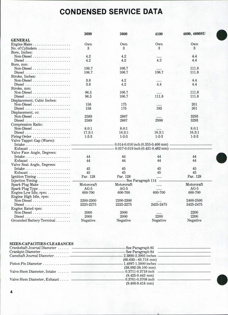
CONDENSED SERVICE DATA
GENERAL
Engine Make
No. of Cylinders
Bore, Inches:
Non-Diesel
Diesel
Bore, mm:
Non-Diesel
Diesel
Stroke, Inches:
Non-Diesel
Diesel
Stroke, mm:
Non-Diesel
Diesel
Displacement, Cubic Inches:
Non-Diesel
Diesel . . . . .
Displacement, cc:
Non-Diesel ....
Diesel
Compression Ratio:
Non-Diesel
Diesel
Firing Order
Valve Tappet Gap (Warm):
Intake
Valve Face Angle, Degrees:
Intake
Exhaust
Valve Seat Angle, Degrees:
Intake
Exhaust
Ignition Timing
SDark Pluer Make
Soark Pluff Tvpe .
Engine Low Idle rpm*
Engine High Idle, rpm:
Non-Diesel
Diesel
Engine Rated rpm:
Non-Diesel
Diesel ..
Grounded Battery Terminal
2600
Own
3
4.2
4.2
106.7
106.7
3.8
3.8
96.5
96.5
158
158
2589
2589
8.0:1
17.3:1
1-2-3
44
44
45
45
Par. 128
Motorcraft
AG-5
600-700
2200-2300
2225-2275
2000
2000
Negative
3600
Own
3
4.2
4.2
106.7
106.7
4.2
4.2
106.7
106.7
175
175
2867
2867
8.0:1
16.3:1
4100
Own
3 \'-'',:
4.2
106.7
4.4
111.8
183
2998
16.3:1
1-2-3 1-2-3
0 014-0 016 inch (0 355-0 406 mm)
0 017-0 019 inch ^^ A9.^ M A9,9. mm^
44
44
45
45
Par. 128
Motorcraft
AG-5
600-700
2200-2300
2225-2275
2000
2000
Negative
44
44
45
45
TTflTlh 11^
600-700
2425-2475
2200
Negative
4600, 4600SU
Own
3
4.4
4.4
111.8
111.8
4.4
4.4
111.8
111.8
201
201
3293
3293
8.0:1
16.3:1
1-2-3
44
44
45
45
Par. 128
Motorcraft
AG-5
600-700
2400-2500
2425-2475
2200
2200
Negative
SIZES-CAPACITIES-CLEARANCES
Crankshaft Journal Diameter —
Crankpin Diameter —
Camshaft Journal Diameter —
Piston Pin Diameter —
Valve Stem Diameter, Intake —
Valve Stem Diameter, Exhaust —
— See Paragraph 85 -
— See Paragraph 84 -
-2.3895-2.3905inches-
(60.693-60.718 mm)
-1.4997-1.5000 inches-
(38.092-38.100 mm)
-0.3711-0.3718 inch -
(9.425-9.443 mm)
-0.3701-0.3708 inch -
(9.400-9.418 mm)
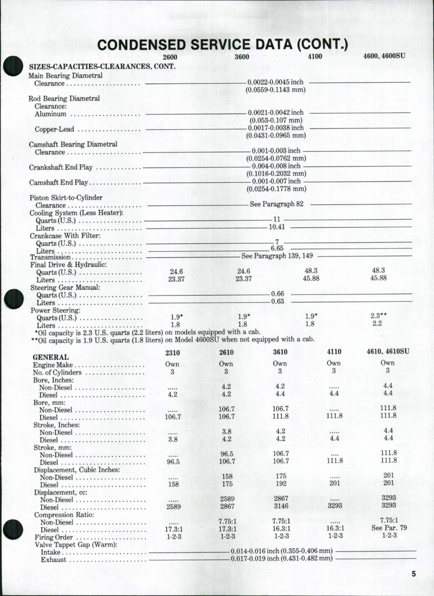
CONDENSED SERVICE DATA (CONT.)
2600 3600 4100 4600,4600SU
SIZES-CAPACITIES-CLEARANCES, CONT.
Main Bearing Diametral
Clearance — 0.0022-0.0045 inch
(0.0559-0.1143 mm)
Rod Bearing Diametral w
Clearance:
Aluminum 0.0021-0.0042 inch
(0.053-0.107 mm)
Copper-Lead 0.0017-0.0038 inch
(0.0431-0.0965 mm)
Camshaft Bearing Diametral
Clearance 0.001-0.003 inch
(0.0254-0.0762 mm)
Crankshaft End Play 0.004-0.008 inch •
(0.1016-0.2032 mm)
Camshaft End Play 0.001-0.007 inch
(0.0254-0.1778 mm)
Piston Skirt-to-Cylinder
Clearance See Paragraph 82
Cooling System (Less Heater):
Quarts(U.S.) H —
Liters 10.41
Crankcase With Filter:
Quarts(U.S.) 7
Liters —- 6.65 — —
Transmission!!!!!!!!!!!!!!!!!!!! See Paragraph 139,149
Final Drive & Hydraulic:
Quarts(U.S.) 24.6 24.6 48.3 48.3
Liters 23.37 23.37 45.88 45.88
Steering Gear Manual:
Quarts (U.S.) —0.66
Liters. 0.63
Power Steering:
Quarts(U.S.) 1.9* 1.9* 1.9* 2.3**
Liters ...... 1.8 1.8 1.8 2.2
*Oil capacity is 2.3 U.S. quarts (2.2 liters) on models equipped with a cab.
**Oil capacity is 1.9 U.S. quarts (1.8 liters) on Model 4600SU when not equipped with a cab.
2310 2610 3610 4110 4610,4610SU
GENERAL
Engine Make Own Own Own Own Own
No. of Cylinders 3 3 3 3 3
Bore, Inches:
Non-Diesel... 4.2 4.2 ..... 4.4
Diesel 4.2 4.2 4.4 4.4 4.4
Bore, mm:
Non-Diesel 106.7 106.7 111.8
Diesel 106.7 106.7 111.8 111.8 111.8
Stroke, Inches:
Non-Diesel 3.8 4.2 4.4
Diesel 3.8 4.2 4.2 4.4 4.4
Stroke, mm:
Non-Diesel ..... 96.5 106.7 .... 111.8
Diesel 96.5 106.7 106.7 111.8 111.8
Displacement, Cubic Inches:
Non-Diesel 158 175 201
Diesel 158 175 192 201 201
Displacement, cc:
Non-Diesel 2589 2867 3293
Diesel 2589 2867 3146 3293 3293
Compression Ratio:
Non-Diesel 7.75:1 7.75:1 7.75:1
Diesel 17.3:1 17.3:1 16.3:1 16.3:1 See Par. 79
Firing Order 1-2-3 1-2-3 1-2-3 1-2-3 1-2-3
Valve Tappet Gap (Warm):
Intake 0.014-0.016 inch (0.355-0.406 mm)
Exhaust 0.017-0.019 inch (0.431-0.482 mm) —
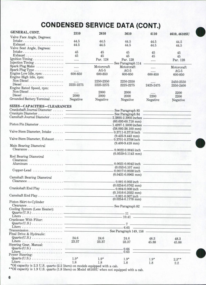
CONDENSED SERVICE DATA (CONT.)
GENERAL, CONT. 2310 2610 3610
Valve Face Angle, Degrees:
Intake 44.5 44.5 44.5
Exhaust 44.5 44.5 44.5
Valve Seat Angle, Degrees:
Intake 45 45 45
Exhaust 45 45 45
Ignition Timing Par. 128 Par. 128
Injection Timing See Paragraph 114
Spark Plug Make Motorcraft Motorcraft
Spark PlugType AG-5 AG-5
Engine Low Idle, rpm: 600-850 600-850 600-850
Engine High Idle, rpm:
Non-Diesel 2250-2350 2250-2350
Diesel 2225-2275 2225-2275 2225-2275
Engine Rated Speed, rpm:
Non-Diesel 2000 2000
Diesel 2000 2000 2000
Grounded Battery Terminal Negative Negative Negative
SIZES - CAPACITIES - CLEARANCES
Crankshaft Journal Diameter See Paragraph 85
Crankpin Diameter See Paragraph 84
Camshaft Journal Diameter — 2.3895-2.3905 inches
(60.693-60.718 mm)
Piston Pin Diameter —_ 1.4997-1.5000 inches
(38.092-38.100 mm)
Valve Stem Diameter, Intake ~ 0.3711-0.3718 inch
(9.425-9.443 mm)
Valve Stem Diameter, Exhaust 0.3701-0.3708 inch
, , . „ . (9.400-9.418 mm)
Mam Bearmg Diametral '
Clearance — 0.0022-0.0045 inch
(0.0559-0.1143 mm)
Rod Bearing Diametral
Clearance:
Aluminum . 0.0021-0.0042 inch
(0.053-0.107 mm)
Copper-Lead 0.0017-0.0038 inch
(0.0431-0.0965 mm)
Camshaft Bearing Diametral
Clearance 0.001-0.003 inch
(0.0254-0.0762 mm)
Crankshaft End Play _ 0.004-0.008 inch
(0.1016-0.2032 mm)
Camshaft End Play _ 0.001-0.007 inch
(0.0254-0.1778 mm)
Piston Skirt-to-Cylinder
Clearance _ See Paragraph 82
Cooling System (Less Heater):
Quarts (U.S.) H
Liters - JQ 41
Crankcase With Filter:
Quarts (U.S.) . 7
Liters-. _ 6.65
Transmission See Paragraph 149,158
Final Drive & Hydraulic:
Quarts(U.S.) 24.6 24.6 24.6 48 3
Liters 23.37 23.37 23.37 45.88
Steering Gear, Manual:
Quarts(U.S.) 0.66
Liters . 0.63
Power Steering:
Quarts (U.S.) 1.9* 1.9* 1.9* 1.9*
Liters 1.8 1.8 1.8 1.8
*Oil capacity is 2.3 U.S. quarts (2.2 liters) on models equipped with a cab.
**Oil capacity is 1.9 U.S. quarts (1.8 liters) on Model 4610SU when not equipped with a cab.
4110
44.5
\ 44.5
45
45
600-850
2425-2475
2200
Negative
4610,4610SU
44.5
44.5
45
45
Par. 128
Motorcraft
AG-5
600-850
2450-2550
2350-2400
2200
2200
Negative
48.3
45.88
2.3**
2.2
6
SHOP MANUAL Paragraphs 1-8
FRONT SYSTEM AND STEERING
(Models 2310-2600-2610-3600-3610-4100-4110 Without Cab)
FRONT AXLE ASSEMBLY AND
STEERING LINKAGE
1. SPINDLE BUSHINGS. To renew
spindle bushings (19 and 22-Fig. 1),
proceed as follows: Support front of
tractor and disconnect steering arms
(17) from wheel spindles (24). Slide spin-
dle out of axle extension (21). Drive old
bushings from front axle extension and
install new ones using a piloted drift or
bushing driver. New bushings will not
require final sizing if not distorted dur-
ing installation. Renew thrust bearing
(23) if worn or rough.
2. AXLE CENTER MEMBER, PIV-
OT PIN AND BUSHINGS. To remove
axle center member (6-Fig 1), support
front of tractor, unbolt axle extensions
from axle center member and swing axle
extensions and wheel assemblies away
from tractor. Remove cap screw (1) and
retainer (2), then unscrew front axle
pivot pin (3). Withdraw axle center
member from either side of tractor.
Press out bushing (7).
To reassemble, press a new bushing
into axle center member. Insert axle
center member into front support, in-
stall pivot pin and tighten pin to 300-320
ft.-lbs. (408-435 N-m). Install retainer
(2) and tighten cap screw (1) to 75 ft.-lbs.
(102 N'm). If removed, tighten radius
rod to axle extension bolts to 130-160
ft.-lbs. (176-217 N-m).
3. FRONT SUPPORT. To remove
front support, proceed as follows:
Remove engine hood, grille, lower hood
to front support bolts and unbolt
radiator from front support. Place floor
jack under front end of transmission and
take weight of tractor from front axle.
Remove front axle pivot pin as in
paragraph 2. Remove bolts retaining
front support casting to engine and
lower front support to floor. When
reinstalling, tighten front support bolts
to 180-220 ft.-lbs. (244-299 N-m).
4. DRAG LINKS AND TOE-IN.
Drag link ends are non-adjustable
automotive type and renewal procedure
is evident. Refer to Fig. 1 for manual
steering tractors and to Fig. 4 for power
steering.
Front wheel toe-in should be V4- to
V2-inch (6.35 to 12.7 mm); vary the
length of each drag link an equal amount
to obtain proper toe-in.
MANUAL STEERING GEAR
5. ADJUSTMENT. To adjust steer-
ing gear, first be sure gear housing is
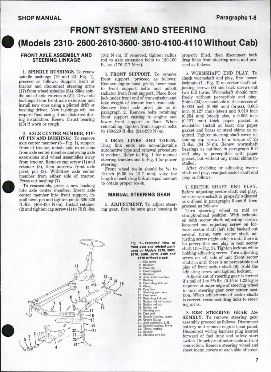
Fig. 1-Exploded view of
front axte and related parts
used on Models 2310, 2600,
2610, 3600, 3610, 4100 and
4110 without a cab.
1. Cap screw
2. Retainer
3. Pivot pin
4. Front support
5. Retainer
6. Axle center member
7. Bushing
8. Front drag link end
9. Clamp
10. Drag link
11. Steering gear assy.
12. Dust cover
13. Rear drag link end
14. Radius rod ball spacer
15. Radius rod cap
16. Radius rod
17. Steering arm
18. Dust seal
19. Spindle bushing, upper
20. Grease fitting
21. Axle extension, L.H.
22. Spindle bushing, lower
23. Thrust bearing
24. Spindle
25. Steering arm key
properly filled, then disconnect both
drag links from steering arms and pro-
ceed as follows:
6. WORMSHAFT END PLAY. To
check wormshaft end play, first loosen
locknuts (1-Fig. 2) on sector shaft ad-
justing screws (8) and back screws out
two full turns. Wormshaft should turn
freely without perceptible end play.
Shims (24) are available in thicknesses of
0.0024 inch (0.060 mm) (brass), 0.005
inch (0.127 mm) (steel) and 0.010 inch
(0.254 mm) (steel); also, a 0.005 inch
(0.127 mm) thick paper gasket is
available. Install at least one paper
gasket and brass or steel shims as re-
quired. Tighten steering shaft cover re-
taining cap screws to a torque of 25
ft.-lbs. (34 N'm). Renew wormshaft
bearings as outlined in paragraph 9 if
end play is perceptible with paper
gasket, but without any metal shims in-
stalled.
After checking or adjusting worm-
shaft end play, readjust sector shaft end
play as follows:
7. SECTOR SHAFT END PLAY.
Before adjusting sector shaft end play,
be sure wormshaft is properly adjusted
as outlined in paragraphs 5 and 6, then
proceed as follows:
Turn steering wheel to mid or
straight-ahead position. With locknuts
on both sector shaft adjusting screws
loosened and adjusting screw on for-
ward sector shaft (left side) backed out
several turns, turn sector shaft ad-
justing screw (right side) in until there is
no perceptible end play in rear sector
shaft (13-Fig. 2). Tighten locknut while
holding adjusting screw. Turn adjusting
screw on left side of unit (front sector
shaft) in until there is no perceptible end
play of front sector shaft (9). Hold the
adjusting screw and tighten locknut.
Adjustment of steering gear is correct
if a pull of 1 to 2% lbs. (0.45 to 1.23 kg) is
required at outer edge of steering wheel
to turn steering gear over center posi-
tion. When adjustment of sector shafts
is correct, reconnect drag links to steer-
ing arms.
8. R&R STEERING GEAR AS-
SEMBLY. To remove steering gear
assembly proceed as follows: Disconnect
battery and remove engine hood panel.
Disconnect wiring harness plug located
forward of fuel tank and safety start
switch. Detach proofmeter cable at front
connection. Remove steering wheel and
sheet metal covers at each side of steer-
Paragraphs 9-11 FORD
ing gear. Disconnect throttle linkage
and remove rear hood panel. Disconnect
fuel gage sender wire and all other wires
which will interfere with fuel tank
removal. Shut off fuel supply, discon-
nect fuel supply line and diesel fuel
return line from tank, then remove fuel
tank assembly. Thoroughly clean steer-
ing gear and surrounding area. Discon-
nect drag links from steering arms, then
unbolt and remove steering gear
assembly from transmission housing.
Drain lubricant from steering gear hous-
ing if unit is to be disassembled.
To reinstall steering gear, reverse
removal procedure. Refill gear housing
with Ford 134 oil.
9. OVERHAUL. Major overhaul of
steering gear unit necessitates removal
of the unit from the tractor as outlined
in paragraph 8. After removing unit,
refer to Fig. 2 and proceed as follows:
Remove steering arm retaining nuts
(14) and pull steering arms (10 and 16)
from sector shafts (9 and 13). Sector
shafts and side covers (4) can be remov-
ed as a unit after removing cover retain-
ing screws. To separate shaft and cover,
remove locknut (1) and thread adjusting
screw (8) into cover until threads clear.
Unbolt steering shaft cover (27) from
gear housing (11) and remove cover,
shaft and ball nut assembly. Do not
disassemble ball nut and steering shaft
assembly (23) as component replace-
ment parts are not available. If steering
shaft and/or ball nut are damaged,
renew the complete assembly. The need
and procedure for further disassembly
and/or overhaul is evident from inspec-
tion of the unit.
Gear housing sector shaft bushings
are not serviced separately from hous-
ing; install a new housing if bushings are
excessively worn. Bushings (5) are
renewable.
Shims (7) on adjusting screws (8) are
available in thicknesses of 0.063, 0.064,
0.066 and 0.069 inch (1.600,1.625,1.676
and 1.752 mm). When reassembling,
select a shim that will provide
0.000-0.002 inch (0.00-0.05 mm)
clearance between adjusting screw head
and slot in sector shaft.
To reassemble, insert steering shaft
and ball nut unit into gear housing with
gear teeth on ball nut forward, then in-
stall steering shaft housing (27) with
proper number of shims as outlined in
paragraph 6. Insert sector shafts, with
their adjusting screws and correct thick-
ness shims, into gear housing so sector
gear teeth and ball nut teeth are timed
as shown in Fig. 3. Place new "0" rings
(6-Fig. 2) on side covers (4) and pull
side covers into place with sector shaft
adjustment screws. Install and tighten
side cover retaining cap screws to a tor-
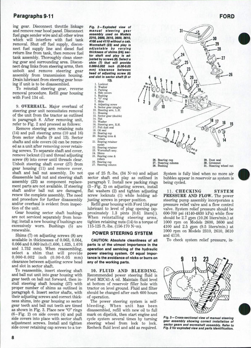
Fig. 2-Exploded view of
manual steering gear
assembly used on Models
2310, 2600, 2610, 3600, 3610,
4100 and 4110 without a cab,
Wormshaft (23) end play Is
adjustable by varying
thickness of shims (24^ sec-
tor shaft end play Is ad-
justed by screws (8), Select a
shim (7) that will provide
0.0000.002 inch (0.000.05
mm) clearance between
head of adjusting screw (8)
and slot In sector shaft (9 or
1. Locknut - r
2. Washer
3. Packing
4. Side covers
5. Bushing
6. "O"ring
7. Shim
8. Adjusting screw
9. Sector gear (single)
10. Steering arm, L.H.
11. Housing
13. Sector gear (double)
14. Nut
15. Washer
16. Steering arm, R.H.
17. Felt dust seal
18. Oil sea]
19. Bearing cup
20. Bearing cone &
rollers
21. Bearing retainer
eyelet
22. Bearing retainer
23. Wormshaft assy.
24. Shims
25. Bearing cone &
rollers
26. Bearing cup
27. Steering column
26. Bearing cup
27. Steering column
28. Bushing
29. Dust seal
30. Grommet
31. Steering wheel nut
que of 25 ft.-lbs. (34 N*m) and adjust
sector shaft end play as outlined in
paragraph 7. Install new packing rings
(3-Fig. 2) on adjusting screws, install
flat washers (2) and tighten adjusting
screw locknuts (1) while holding ad-
justing screws in proper position.
Refill gear housing with Ford 134 gear
lubricant to level of plug opening (ap-
proximately 1.3 pints [0.61 liters]).
When reinstalling steering arms,
tighten retaining nuts (14) to a torque of
115-125 ft.-lbs. (156-170 N-m).
POWER STEERING SYSTEM
CAUTION: Absolute cleanliness of all
parts Is of the utmost importance in the
operation and servicing of the hydraulic
power steering system. Of equal impor-
tance is the avoidance of nicks or burrs on
any of the working parts.
10. FLUID AND BLEEDING.
Recommended power steering fluid is
Ford M2C41-A oil. Maintain fluid level
at bottom of reservoir filler hole with
tractor on level ground. Fluid and filter
should be changed after each 600 hours
of operation.
The power steering system is self-
bleeding. When unit has been
disassembled, refill with new oil to full
mark on dipstick, then start engine and
cycle system several times by turning
steering wheel from lock to lock.
Recheck fiuid level and add as required.
System is fully bled when no more air
bubbles appear in reservoir as system is
being cycled.
11. CHECKING SYSTEM
PRESSURE AND FLOW. The power
steering pump assembly incorporates a
pressure relief valve and a fiow control
valve. System relief pressure should be
600-700 psi (4140-4830 kPa) while fiow
should be 2.7 gpm (10.26 liters/min.) at
1000 rpm on Models 2600, 3600 and
4100 and 2.5 gpm (9.5 liters/min.) at
1000 rpm on Models 2310, 2610, 3610
and 4110.
To check system relief pressure, in-
9 13 23
Fig. 3- Cross-sectlonai view of manual steering
gear assembly showing correct Installation of
sector gears and wormshaft assembly. Refer to
Fig. 2 for exploded view and parts Identification.
8
SHOP MANUAL Paragraphs 12-14
stall a **T" fitting in pressure line
(19 - Fig. 4) at pump connection and con-
nect a 0-1000 psi (0-7000 kPa) gage to
fitting. With engine running at 1000
rpm and front wheels turned against
lock, gage reading should be 600-700 psi
(4140-4830 kPa).
CAUTION: When checking system relief
pressure, hold steering wheei against iock
oniy iong enough to observe gage reading;
pump may be damaged if steering wheei
is held in this position for an excessive
length of time.
Pump must be disassembled to adjust
opening pressure. Refer to paragraph
12 and Fig. 5. Shims (25) control system
pressure and are available in thicknesses
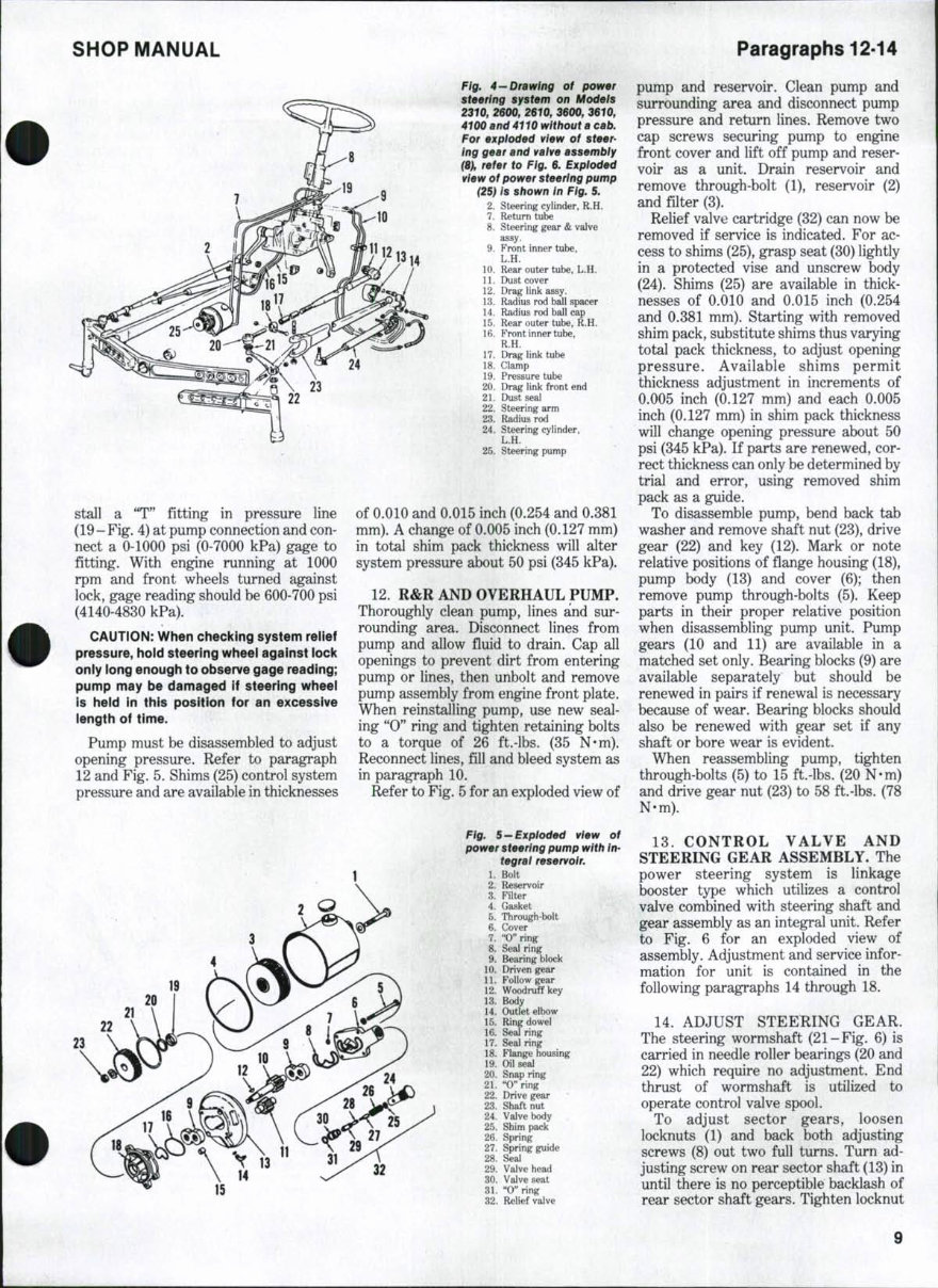
Fig. 4 —Drawing of power
steering system on Models
2310, 2600, 2610, 3600, 3610,
4100 and 4110 without a cab.
For exploded view of steer-
ing gear and vaive assembly
(8), refer to Fig. 6. Exploded
view of power steering pump
(25> /5 shown in Fig. 5.
2. Steering cylinder, R.H.
7. Return tube
8. Steering gear & valve
assy.
9. Front inner tube,
L.H.
10. Rear outer tube, L.H.
11. Dust cover
12. Drag link assy.
13. Radius rod bEill spacer
14. Radius rod ball cap
15. Rear outer tube, R.H.
16. Front inner tube,
R.H.
17. Drag link tube
18. Clamp
19. Pressure tube
20. Drag link front end
21. Dust seal
22. Steering arm
23. Radius rod
24. Steering cylinder,
L.H.
25. Steering pump
of 0.010 and 0.015 inch (0.254 and 0.381
mm). A change of 0.005 inch (0.127 mm)
in total shim pack thickness will alter
system pressure about 50 psi (345 kPa).
12. R&R AND OVERHAUL PUMP.
Thoroughly clean pump, lines and sur-
rounding area. Disconnect lines from
pump and allow fiuid to drain. Cap all
openings to prevent dirt from entering
pump or lines, then unbolt and remove
pump assembly from engine front plate.
When reinstalling pump, use new seal-
ing "0" ring and tighten retaining bolts
to a torque of 26 ft.-lbs. (35 N-m).
Reconnect lines, fill and bleed system as
in paragraph 10.
Refer to Fig. 5 for an exploded view of
Fig. 5 — Exploded view of
power steering pump with in-
tegral reservoir.
1. Bolt
2. Reservoir
3. Filter
4. Gasket
5. Through-bolt
6. Cover
7. "0" ring
8. Seal ring
9. Bearing block
10. Driven gear
11. Follow gear
12. Woodruff key
13. Body
14. Outlet elbow
15. Ring dowel
16. Seal ring
17. Seal ring
18. Flange housing
19. Oil seal
20. Snap ring
21. "O"ring
22. Drive gear
23. Shaft nut
24. Valve body
25. Shim pack
26. Spring
27. Spring guide
28. Seal
29. Valve head
30. Valve seat
31. "Oaring
32. Relief valve
32
pump and reservoir. Clean pump and
surrounding area and disconnect pump
pressure and return lines. Remove two
cap screws securing pump to engine
front cover and lift off pump and reser-
voir as a unit. Drain reservoir and
remove through-bolt (1), reservoir (2)
and filter (3).
Relief valve cartridge (32) can now be
removed if service is indicated. For ac-
cess to shims (25), grasp seat (30) lightly
in a protected vise and unscrew body
(24). Shims (25) are available in thick-
nesses of 0.010 and 0.015 inch (0.254
and 0.381 mm). Starting with removed
shim pack, substitute shims thus varying
total pack thickness, to adjust opening
pressure. Available shims permit
thickness adjustment in increments of
0.005 inch (0.127 mm) and each 0.005
inch (0.127 mm) in shim pack thickness
will change opening pressure about 50
psi (345 kPa). If parts are renewed, cor-
rect thickness can only be determined by
trial and error, using removed shim
pack as a guide.
To disassemble pump, bend back tab
washer and remove shaft nut (23), drive
gear (22) and key (12). Mark or note
relative positions of fiange housing (18),
pump body (13) and cover (6); then
remove pump through-bolts (5). Keep
parts in their proper relative position
when disassembling pump unit. Pump
gears (10 and 11) are available in a
matched set only. Bearing blocks (9) are
available separately but should be
renewed in pairs if renewal is necessary
because of wear. Bearing blocks should
also be renewed with gear set if any
shaft or bore wear is evident.
When reassembling pump, tighten
through-bolts (5) to 15 ft.-lbs. (20 N-m)
and drive gear nut (23) to 58 ft.-lbs. (78
N-m).
13. CONTROL VALVE AND
STEERING GEAR ASSEMBLY. The
power steering system is linkage
booster type which utilizes a control
valve combined with steering shaft and
gear assembly as an integral unit. Refer
to Fig. 6 for an exploded view of
assembly. Adjustment and service infor-
mation for unit is contained in the
following paragraphs 14 through 18.
14. ADJUST STEERING GEAR.
The steering wormshaft (21-Fig. 6) is
carried in needle roller bearings (20 and
22) which require no adjustment. End
thrust of wormshaft is utilized to
operate control valve spool.
To adjust sector gears, loosen
locknuts (1) and back both adjusting
screws (8) out two full turns. Turn ad-
justing screw on rear sector shaft (13) in
until there is no perceptible backlash of
rear sector shaft gears. Tighten locknut
9
Paragraphs 15-17
while holding adjusting screw in this
position. With rear sector shaft ad-
justed, turn adjusting screw on front
sector shaft (9) in until there is no
perceptible backlash of front sector
shaft gears, then tighten locknut while
holding adjusting screw in this position.
15. R&R STEERING GEAR AND
CONTROL VALVE ASSEMBLY.
Remove steering gear by disconnecting
oil lines and using procedure outlined in
paragraph 8.
To reinstall steering gear assembly,
reverse removal procedure. Refill and
bleed power steering system as outlined
in paragraph 10. Refill steering gear
with Ford 134 oil.
16. RENEW CONTROL VALVE
UPPER SEAL. If power steering fiuid
leaks from steering column housing, the
control valve upper seal (40-Fig. 6) is
leaking and can be renewed as follows:
Follow general procedures outlined in
paragraph 15, except that fuel lines do
not need to be disconnected nor does
fuel tank need to be removed.
Thoroughly clean steering gear and con-
trol valve assembly. Remove cap screws
retaining steering column (41) to steer-
ing gear and remove steering column.
Remove seal from lower end of steering
column with a suitable puller. Drive
bushing (42) from upper end of steering
column with a 1-inch (25.4 mm) diameter
dowel.
n
'
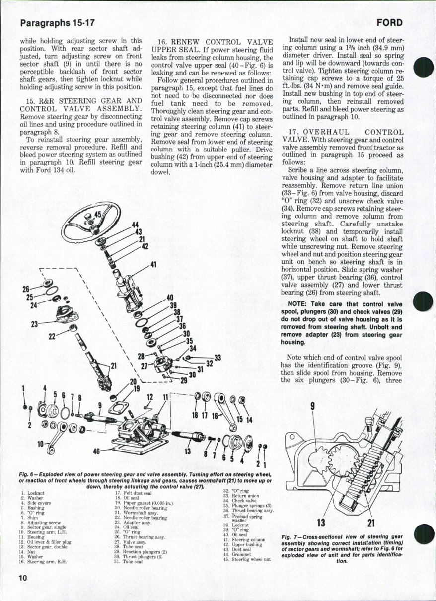
Fig. 6 — Exploded view of power steering gear and vaive assembiy. Turning effort on steering wheel,
or reaction of front wheels through steering linkage and gears, causes wormshaft (21) to move up or
down, thereby actuating the control valve (27).
1. Locknut 17. Felt dust seal
2. Washer 18. Oil seal ^^•
4. Side covers 19. Paper gasket (0.005 in.) «g
37. Preload spring
39. "O" ring
40. Oil seal
41. Steering column
42. Upper bushing
45. Steering wheel nut
7. Shim
8. Adjusting screw
9. Sector gear, single
10. Steering arm, L.H.
11. Housing
12. Oil lever &fillerplug
13. Sector gear, double
14. Nut
15. Washer
16. Steering arm, R.H.
22. Needle roller bearing
23. Adapter assy.
24. Oil seal
25. "O"ring
26. Thrust bearing assy.
27. Valve assy.
28. Tube seat
29. Reaction plungers (2)
30. Thrust plungers (6)
31. Tube seat
FORD
Install new seal in lower end of steer-
ing column using a 1% inch (34.9 mm)
diameter driver. Install seal so spring
and lip will be downward (towards con-
trol valve). Tighten steering column re-
taining cap screws to a torque of 25
ft.-lbs. (34 N-m) and remove seal guide.
Install new bushing in top end of steer-
ing column, then reinstall removed
parts. Refill and bleed power steering as
outlined in paragraph 10.
17. OVERHAUL CONTROL
VALVE. With steering gear and control
valve assembly removed from' tractor as
outlined in paragraph 15 proceed as
follows:
Scribe a line across steering column,
valve housing and adapter to facilitate
reassembly. Remove return line union
(33-Fig. 6) from valve housing, discard
"0" ring (32) and unscrew check valve
(34). Remove cap screws retaining steer-
ing column and remove column from
steering shaft. Carefully unstake
locknut (38) and temporarily install
steering wheel on shaft to hold shaft
while unscrewing nut. Remove steering
wheel and nut and position steering gear
unit on bench so steering shaft is in
horizontal position. Slide spring washer
(37), upper thrust bearing (36), control
valve assembly (27) and lower thrust
bearing (26) from steering shaft.
NOTE: Take care that control valve
spool, plungers (30) and check vaives (29)
do not drop out of vaive housing as it is
removed from steering shaft. Unboit and
remove adapter (23) from steering gear
housing.
Note which end of control valve spool
has the identification groove (Fig. 9),
then slide spool from housing. Remove
the six plungers (30-Fig. 6), three
Fig. 7—Cross-sectional view of steering gear
assembly showing correct Installation (timing)
of sector gears and wormshaft; refer to Fig. 6 for
exploded view of unit and for parts Identifica-
tion.
10
SHOPMANAUL Paragraph 18
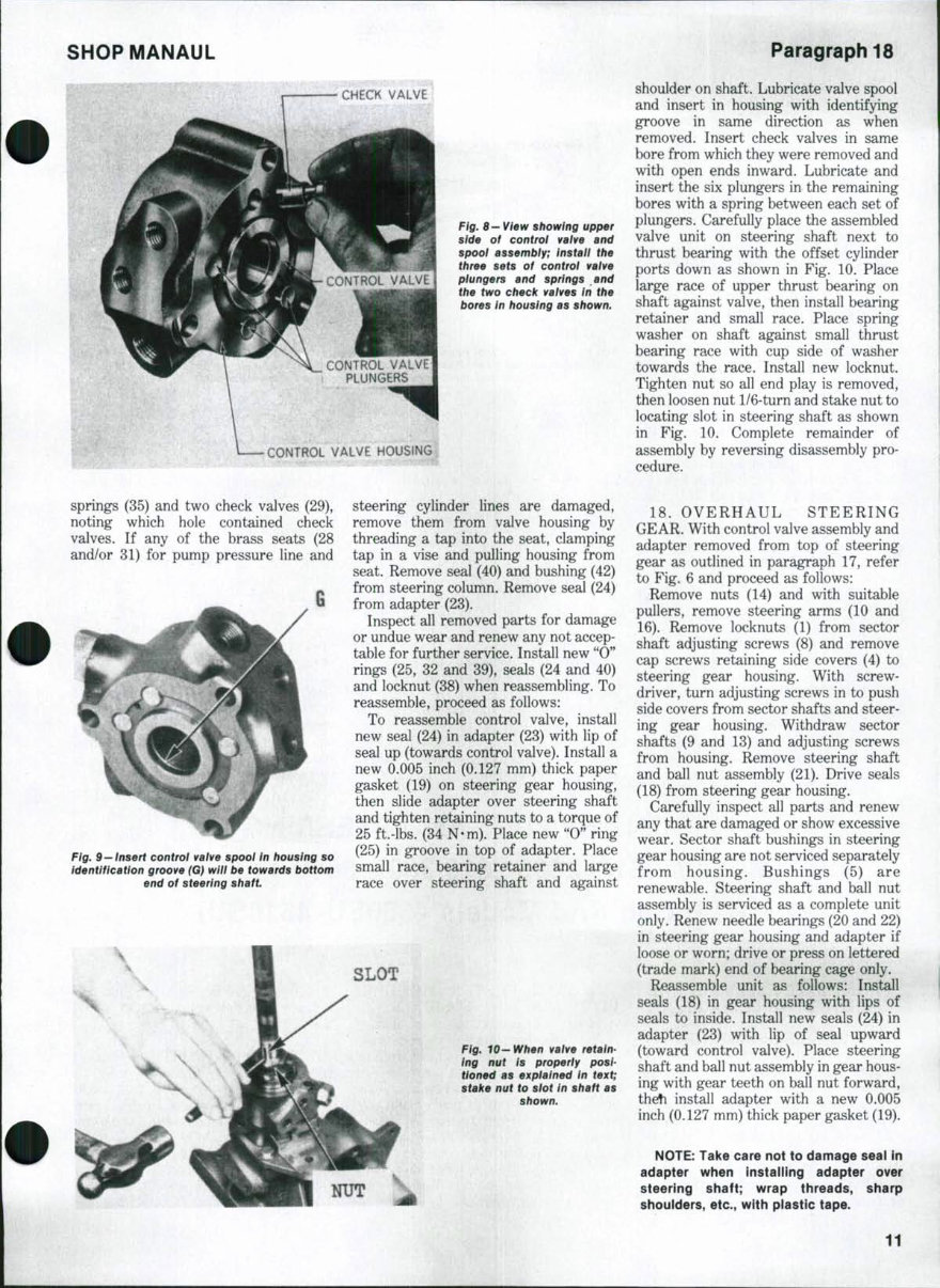
CHECK VALVE
CONTROL VALVE
PLUNGERS
Fig. 8 — View showing upper
side of control valve and
spool assembly; install the
three sets of control valve
plungers and springs and
the two check vaives in the
bores In housing as shown.
CONTROL VALVE HOUSING
shoulder on shaft. Lubricate valve spool
and insert in housing with identifying
groove in same direction as when
removed. Insert check valves in same
bore from which they were removed and
with open ends inward. Lubricate and
insert the six plungers in the remaining
bores with a spring between each set of
plungers. Carefully place the assembled
valve unit on steering shaft next to
thrust bearing with the offset cylinder
ports down as shown in Fig. 10. Place
large race of upper thrust bearing on
shaft against valve, then install bearing
retainer and small race. Place spring
washer on shaft against small thrust
bearing race with cup side of washer
towards the race. Install new locknut.
Tighten nut so all end play is removed,
then loosen nut 1/6-turn and stake nut to
locating slot in steering shaft as shown
in Fig. 10. Complete remainder of
assembly by reversing disassembly pro-
cedure.
springs (35) and two check valves (29),
noting which hole contained check
valves. If any of the brass seats (28
and/or 31) for pump pressure line and
Fig. 9—Insert control valve spool In housing so
identification groove (G) will be towards bottom
end of steering shaft.
\
steering cylinder lines are damaged,
remove them from valve housing by
threading a tap into the seat, clamping
tap in a vise and pulling housing from
seat. Remove seal (40) and bushing (42)
from steering column. Remove seal (24)
from adapter (23).
Inspect all removed parts for damage
or undue wear and renew any not accep-
table for further service. Install new "0"
rings (25, 32 and 39), seals (24 and 40)
and locknut (38) when reassembling. To
reassemble, proceed as follows:
To reassemble control valve, install
new seal (24) in adapter (23) with lip of
seal up (towards control valve). Install a
new 0.005 inch (0.127 mm) thick paper
gasket (19) on steering gear housing,
then slide adapter over steering shaft
and tighten retaining nuts to a torque of
25 ft.-lbs. (34 N-m). Place new "0" ring
(25) in groove in top of adapter. Place
small race, bearing retainer and large
race over steering shaft and against
SLOT
Fig. 10-When valve retain-
ing nut is properly posi-
tioned as explained in text;
stake nut to slot in shaft as
shown.
18. OVERHAUL STEERING
GEAR. With control valve assembly and
adapter removed from top of steering
gear as outlined in paragraph 17, refer
to Fig. 6 and proceed as follows:
Remove nuts (14) and with suitable
pullers, remove steering arms (10 and
16). Remove locknuts (1) from sector
shaft adjusting screws (8) and remove
cap screws retaining side covers (4) to
steering gear housing. With screw-
driver, turn adjusting screws in to push
side covers from sector shafts and steer-
ing gear housing. Withdraw sector
shafts (9 and 13) and adjusting screws
from housing. Remove steering shaft
and ball nut assembly (21). Drive seals
(18) from steering gear housing.
Carefully inspect all parts and renew
any that are damaged or show excessive
wear. Sector shaft bushings in steering
gear housing are not serviced separately
from housing. Bushings (5) are
renewable. Steering shaft and ball nut
assembly is serviced as a complete unit
only. Renew needle bearings (20 and 22)
in steering gear housing and adapter if
loose or worn; drive or press on lettered
(trade mark) end of bearing cage only.
Reassemble unit as follows: Install
seals (18) in gear housing with lips of
seals to inside. Install new seals (24) in
adapter (23) with lip of seal upward
(toward control valve). Place steering
shaft and ball nut assembly in gear hous-
ing with gear teeth on ball nut forward,
thefi install adapter with a new 0.005
inch (0.127 mm) thick paper gasket (19).
NOTE: Take care not to damage seai in
adapter when installing adapter over
steering shaft; wrap threads, sharp
shouiders, etc., with piastic tape.
11
You're Reading a Preview
What's Included?
Fast Download Speeds
Online & Offline Access
Access PDF Contents & Bookmarks
Full Search Facility
Print one or all pages of your manual
$36.99
Viewed 54 Times Today


Secure transaction
What's Included?
Fast Download Speeds
Online & Offline Access
Access PDF Contents & Bookmarks
Full Search Facility
Print one or all pages of your manual
$36.99
This manual is suitable for both first-time owners and amateur enthusiasts, as well as professional technicians. It is designed in an easy-to-read format and provides all the necessary information to perform procedures accurately. Keeping this service manual accessible and referring to it regularly is recommended. Regular and preventive maintenance outlined in the manual can help save time and money by preventing premature failure and unnecessary repairs.
- BRAKES
- CLUTCH
- COOLING SYSTEM
- DIESEL FUEL SYSTEM
- DIFFERENTIAL
- DIFFERENTIAL LOCK
- ELECTRICAL SYSTEM
- ENGINE
- FINAL DRIVE
- FRONT SYSTEM
- HYDRAULIC SYSTEM
- POWER TAKE-OFF
- TRANSMISSION
File Format: PDF
Compatibility: All Versions of Windows & Mac
Language: English
Requirements: Adobe Reader


