

Ford 1000 1600 8000 8600 9000 9600 9700 Tw10-20-30 Wsm
What's Included?
Fast Download Speeds
Online & Offline Access
Access PDF Contents & Bookmarks
Full Search Facility
Print one or all pages of your manual
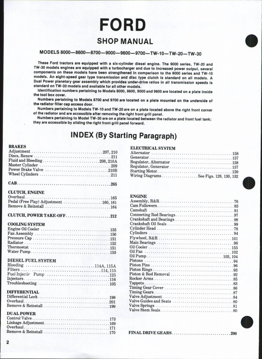
FORD
SHOP MANUAL
MODELS8000—8600—8700—9000—9600—9700—TW-10—TW-20—TW-30
These Ford tractors are equipped with a six-cylinder diesel engine. The 9000 series, TW-20 and
TW-30 modeis engines are equipped with a turbocharger and due to increased power output, severai
components on these modeis have been strengthened in comparison to the 8000 series and TW-10
modeis. An eight-speed gear type transmission and disc type ciutch is standard on aii models. A
Dual Power planetary gear assembly which provides under-drive ratios in ail transmission speeds is
standard on TW-30 modeis and avaiiabie for ail other modeis.
identification numbers pertaining to Modeis 8000, 8600, 9000 and 9600 are iocated on a piate inside
the tool box cover.
Numbers pertaining to Modeis 8700 and 9700 are located on a piate mounted on the underside of
the radiator filier cap access door.
Numbers pertaining to Models TW-10 and TW-20 are on a piate located above the right front corner
of the radiator and are accessible after removing the right front grill panel.
Numbers pertaining to Modei TW-30 are on a plate iocated between the radiator and front fuel tani<;
they are accessibie by siiding the right front griii panei forward.
INDEX (By Starting Paragraph)
BRAKES
Adjustment .207,210
Discs, Renew 211
Fluid and Bleeding 208,210A
Master Cylinder 209
Power Brake Valve 210B
Wheel Cylinders 211
CAB.
.265
CLUTCH, ENGINE
Overhaul 165
Pedal (Free Play) Adjustment 160,161
Remove & Reinstall 164
CLUTCH, POWER TAKE-OFF 212
COOLING SYSTEM
Engine Oil Cooler 155
Fan Assembly 156
Pressure Cap 151
Radiator 152
Thermostat 151
Water Pump I53
DIESEL FUEL SYSTEM
Bleeding 114A, 115A
Filters .114^ I I 5
Fuel Injectir Pump 125
Injectors 116
Troubleshooting 105
DIFFERENTIAL
Differential Lock 198
Overhaul 201
Remove & Reinstall 199
DUAL POWER
Control Valve I73
Linkage Adjustment 169
Overhaul 171
Remove & Reinstall 170
ELECTRICAL SYSTEM
Alternator 158
Generator 157
Regulator, Alternator 158
Regulator, Generator 157
Starting Motor 159
Wiring Diagrams See Figs. 128,130,132
ENGINE
Assembly, R&R 76
Cam Followers 83
Camshaft 91
Connecting Rod Bearings 97
Crankshaft and Bearings 98
Crankshaft Oil Seals 99
Cylinder Head 78
Cylinders 94
Flywheel, R&R lOl
Main Bearings 98
Oil Cooler 155
Oil Pan 102
Oil Pump 103,104
Pistons 94
Piston Pins 96
Piston Rings 93
Piston & Rod Removal 92
Rocker Arms 85
Tappets .83
Timing Gear Cover 86
Timing Gears 87
Valve Adjustment 84
Valve Guides and Seats 80
Valve Springs 81
Valve Stem Seals 80
FINAL DRIVE GEARS 206
INDEX CONT.
FRONT AXLE [Except Front Wheel Drive]
Axle Main (Center) Member 3.31
Front Support (Pedestal) 6.33
Pivot Pins .3,31
Steering Spindles 2,30
Tie Rods And Toe-in 4, 32
FRONT WHEEL DRIVE
Axle Main (Center) Member 45
Axle Shafts 49
Differential And Bevel Gears 52
Front Support 56
Pivot Pins 45
Steering Knuckles 50
Tie Rods And Toe-in 45A
Transfer Box 59
Wheel Hub And Planetary Carrier 46
HYDRAULIC LIFT SYSTEM
Adjustments 230
Filters 227
Flow Control Valve 243
Fluid 226
Lift Cover Assembly, R&R 245
Lift Cylinder 252
Lift Shaft (Rockshaft) 253
Linkage 254,257
Pressure Relief Valve, Overhaul 241, 242
Pump 233
Relief Pressure, Adjust 229
Remote Control Valves 258
Torsion Bar 257
Troubleshooting 228
INTERCOOLER
Fan 143
Heat Exchanger 147
LOW PRESSURE OIL SYSTEM
Pump
Regulator Valve
POWER STEERING
Bleed System 7,34
Pump 11.36
Reservoir "^t 34
Steering (Hydramotor) Gear Unit 13
Steering (Ross) Gear Unit 19
Steering Motor 22,38
Troubleshooting ^
POWER TAKE-OFF
Adjust Control Linkage 215
Clutch 220,221
Control Valve 220,221
OutputShaft 219
Pressure Test, Pto System 213
Reduction Gears 217
Troubleshooting 212
REAR AXLE
Axle Housings 204
Bearing Adjustment — 205
Shaft, Remove & Reinstall 205
TRANSMISSION
Assembly, Remove & Reinstall 187
Overhaul 1^1
Shifter Mechanism 189,190
TRANSMISSION HANDBRAKE 196
TURBOCHARGER
Overhaul 138,140
Remove & Reinstall 137
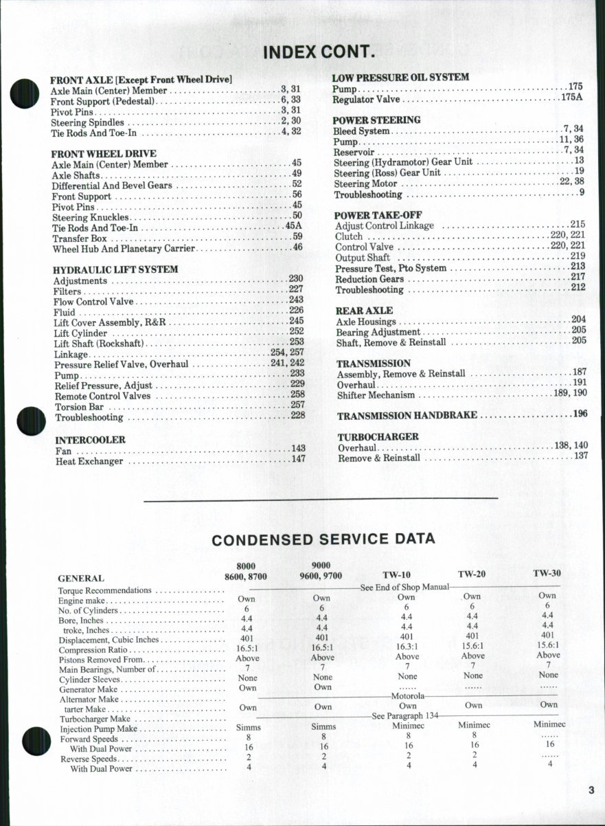
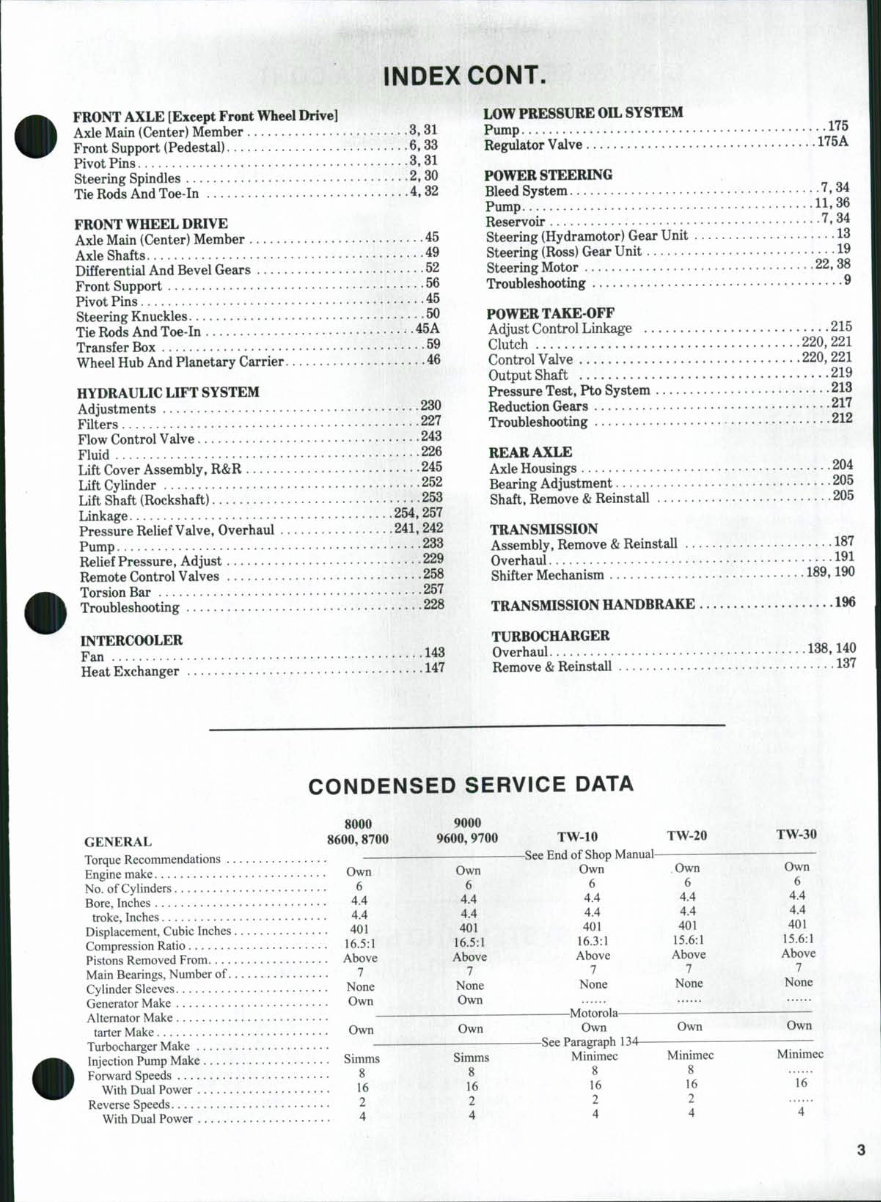
CONDENSED SERVICE DATA
8000
GENERAL 8600,8700
Torque Recommendations
Engine make Own
No. of Cylinders 6
Bore, Inches 4.4
troke. Inches 4.4
Displacement, Cubic Inches 401
Compression Ratio 16.5:1
Pistons Removed From Above
Main Bearings, Number of 7
Cylinder Sleeves None
Generator Make Own
Alternator Make
tarter Make Own
Turbocharger Make
Injection Pump Make Simms
Forward Speeds 8
With Dual Power 16
Reverse Speeds 2
With Dual Power 4
9000
9600,9700
Own
6
4.4
4.4
401
16.5:1
Above
7
None
Own
Own
Simms
8
16
2
4
TW-10 TW-20
-See End of Shop Manual
Own . Own
6 6
4.4 4.4
4.4 4.4
401 401
16.3:1 15.6:1
Above Above
7 :. 7
None None
-Motorola-
Own
-See Paragraph 134-
Minimec
S
16
2
4
Own
Minimec
8
16
2
4
TW-30
Own
6
4.4
4.4
401
15.6:1
Above
7
None
Own
Minimec
INDEX CONT.
FRONT AXLE [Except Front Wheel Drive]
Axle Main (Center) Member 3.31
Front Support (Pedestal) 6.33
Pivot Pins .3,31
Steering Spindles 2,30
Tie Rods And Toe-in 4, 32
FRONT WHEEL DRIVE
Axle Main (Center) Member 45
Axle Shafts 49
Differential And Bevel Gears 52
Front Support 56
Pivot Pins 45
Steering Knuckles 50
Tie Rods And Toe-in 45A
Transfer Box 59
Wheel Hub And Planetary Carrier 46
HYDRAULIC LIFT SYSTEM
Adjustments 230
Filters 227
Flow Control Valve 243
Fluid 226
Lift Cover Assembly, R&R 245
Lift Cylinder 252
Lift Shaft (Rockshaft) 253
Linkage 254,257
Pressure Relief Valve, Overhaul 241, 242
Pump 233
Relief Pressure, Adjust 229
Remote Control Valves 258
Torsion Bar 257
Troubleshooting 228
INTERCOOLER
Fan 143
Heat Exchanger 147
LOW PRESSURE OIL SYSTEM
Pump
Regulator Valve
POWER STEERING
Bleed System 7,34
Pump 11.36
Reservoir "^t 34
Steering (Hydramotor) Gear Unit 13
Steering (Ross) Gear Unit 19
Steering Motor 22,38
Troubleshooting ^
POWER TAKE-OFF
Adjust Control Linkage 215
Clutch 220,221
Control Valve 220,221
OutputShaft 219
Pressure Test, Pto System 213
Reduction Gears 217
Troubleshooting 212
REAR AXLE
Axle Housings 204
Bearing Adjustment — 205
Shaft, Remove & Reinstall 205
TRANSMISSION
Assembly, Remove & Reinstall 187
Overhaul 1^1
Shifter Mechanism 189,190
TRANSMISSION HANDBRAKE 196
TURBOCHARGER
Overhaul 138,140
Remove & Reinstall 137
CONDENSED SERVICE DATA
8000
GENERAL 8600,8700
Torque Recommendations
Engine make Own
No. of Cylinders 6
Bore, Inches 4.4
troke. Inches 4.4
Displacement, Cubic Inches 401
Compression Ratio 16.5:1
Pistons Removed From Above
Main Bearings, Number of 7
Cylinder Sleeves None
Generator Make Own
Alternator Make
tarter Make Own
Turbocharger Make
Injection Pump Make Simms
Forward Speeds 8
With Dual Power 16
Reverse Speeds 2
With Dual Power 4
9000
9600,9700
Own
6
4.4
4.4
401
16.5:1
Above
7
None
Own
Own
Simms
8
16
2
4
TW-10 TW-20
-See End of Shop Manual
Own . Own
6 6
4.4 4.4
4.4 4.4
401 401
16.3:1 15.6:1
Above Above
7 :. 7
None None
-Motorola-
Own
-See Paragraph 134-
Minimec
S
16
2
4
Own
Minimec
8
16
2
4
TW-30
Own
6
4.4
4.4
401
15.6:1
Above
7
None
Own
Minimec
Paragraph 1 FORD
CONDENSED SERVICE DATA CONT.
8000, 9000,
TF?^-^ 8600,8700 9600,9700 TW-10 TW-20. TW-30
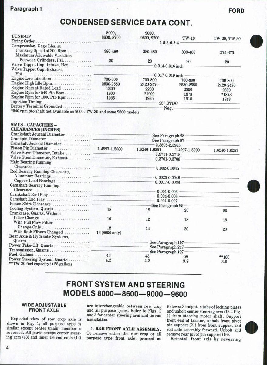
Firing Order 1-5-3-6-2-4
Compression, Gage Lbs. at
Cranking Speed of 200 Rpm 380 480 380-480 300-400 275-375
Maximum Allowable Variation
Between Cylinders, Psi 20 20 20 20
Valve Tappet Gap, Intake, Hot 0.014-0 016 inch —
Valve Tappet Gap, Exhaust,
0.017-0.019 inch
Engine Low Idle Rpm .: 700-800 700-800 700-800 700-800
Engme High Idle Rpm 2530-2580 2420-2470 2530-2580 2420-2470
Engine Rpm at Rated Load 2300 2200 2300 2300
Engine Rpm for 540 Pto Rpm 1900 *1900 1873 •1873
Engine Rpm for 1000 Pto Rpm 1935 1935 1918 1918
Injection Timing 23** BTDC —
Battery Terminal Grounded p^g-
•540 rpm pto shaft not available on 9000, TW 30 and some 9600 models.
SIZES - CAPACITIES -
CLEARANCES [INCHES]
Crankshaft Journal Diameter See Paragraph 98
Crankpin Diameter _ See Paragraph 9 7 -
Oamsnait Journal Diameter 2.3895-2.3905
Piston Pin Diameter 1.4997-1.5000 1.6246-1.6251 * 1.4997-1.5000 1.6246-1.6251
Valve Stem Diameter, Intake 0.3711-0.3718
Valve Stem Diameter, Exhaust — 0.3701-0.3708 - —^
Main Bearing Running
Clearance ^ 0.002-0.0045 ~
Rod Bearing Running Clearance,
Aluminum Bearings 0.0025-0.0046
Copper Lead Bearings 0.0017-0 0038
Camshaft Bearing Running
Clearance 0.001-0.003 ^
Crankshaft End Play — 0.004-0 008
Camshaft End Play 0 001-0 007 —
Piston Skirt Clearance See Paragraph 95 ^
Cooling System, Quarts 18 19 20 20
Crankcase, Quarts, Without
Filter Change 10 12 18 m
With FuU Flow Filter ^^
Change Only 12 14 20 M
With Both Filters Changed 13 (8000 only)
Rear Axle & Hydraulic Systems,
~ See Paragraph 197
43 43 58 **100
Power Steering System, Quarts 4.2 4 2 3 o q Q
**TW-20 fuel capacity is 58 gallons. ' *
FRONT SYSTEM AND STEERING
MODELS 8000—8600—9000—9600
WIDE ADJUSTABLE are interchangeable between row crop follows: Straighten tabs of locking plates
FRONT AXLE and all purpose types. Refer to Figs. 2 and unbolt center steering arm (13—Fig.
„ , , , . , and 3 for center steering arm and tie rod 1) from steering motor shaft. Support
Exploded view of row crop axle is installation. front end of tractor, unbolt front pivot
shown m Fig. 1; all purpose type is pin support (21) from front support and
similar except center (mam) member is 1. R&R FRONT AXLE ASSEMBLY, roll axle assembly forward. Unbolt and
reversed. All parts except center steer- To remove either the row crop or all remove rear pivot pin support (16).
mg arm (13) and inner tie rod ends (12) purpose type front axle, proceed as Reinstall front axle by reversing

Paragraph 1 FORD
CONDENSED SERVICE DATA CONT.
8000, 9000,
TF?^-^ 8600,8700 9600,9700 TW-10 TW-20. TW-30
Firing Order 1-5-3-6-2-4
Compression, Gage Lbs. at
Cranking Speed of 200 Rpm 380 480 380-480 300-400 275-375
Maximum Allowable Variation
Between Cylinders, Psi 20 20 20 20
Valve Tappet Gap, Intake, Hot 0.014-0 016 inch —
Valve Tappet Gap, Exhaust,
0.017-0.019 inch
Engine Low Idle Rpm .: 700-800 700-800 700-800 700-800
Engme High Idle Rpm 2530-2580 2420-2470 2530-2580 2420-2470
Engine Rpm at Rated Load 2300 2200 2300 2300
Engine Rpm for 540 Pto Rpm 1900 *1900 1873 •1873
Engine Rpm for 1000 Pto Rpm 1935 1935 1918 1918
Injection Timing 23** BTDC —
Battery Terminal Grounded p^g-
•540 rpm pto shaft not available on 9000, TW 30 and some 9600 models.
SIZES - CAPACITIES -
CLEARANCES [INCHES]
Crankshaft Journal Diameter See Paragraph 98
Crankpin Diameter _ See Paragraph 9 7 -
Oamsnait Journal Diameter 2.3895-2.3905
Piston Pin Diameter 1.4997-1.5000 1.6246-1.6251 * 1.4997-1.5000 1.6246-1.6251
Valve Stem Diameter, Intake 0.3711-0.3718
Valve Stem Diameter, Exhaust — 0.3701-0.3708 - —^
Main Bearing Running
Clearance ^ 0.002-0.0045 ~
Rod Bearing Running Clearance,
Aluminum Bearings 0.0025-0.0046
Copper Lead Bearings 0.0017-0 0038
Camshaft Bearing Running
Clearance 0.001-0.003 ^
Crankshaft End Play — 0.004-0 008
Camshaft End Play 0 001-0 007 —
Piston Skirt Clearance See Paragraph 95 ^
Cooling System, Quarts 18 19 20 20
Crankcase, Quarts, Without
Filter Change 10 12 18 m
With FuU Flow Filter ^^
Change Only 12 14 20 M
With Both Filters Changed 13 (8000 only)
Rear Axle & Hydraulic Systems,
~ See Paragraph 197
43 43 58 **100
Power Steering System, Quarts 4.2 4 2 3 o q Q
**TW-20 fuel capacity is 58 gallons. ' *
FRONT SYSTEM AND STEERING
MODELS 8000—8600—9000—9600
WIDE ADJUSTABLE are interchangeable between row crop follows: Straighten tabs of locking plates
FRONT AXLE and all purpose types. Refer to Figs. 2 and unbolt center steering arm (13—Fig.
„ , , , . , and 3 for center steering arm and tie rod 1) from steering motor shaft. Support
Exploded view of row crop axle is installation. front end of tractor, unbolt front pivot
shown m Fig. 1; all purpose type is pin support (21) from front support and
similar except center (mam) member is 1. R&R FRONT AXLE ASSEMBLY, roll axle assembly forward. Unbolt and
reversed. All parts except center steer- To remove either the row crop or all remove rear pivot pin support (16).
mg arm (13) and inner tie rod ends (12) purpose type front axle, proceed as Reinstall front axle by reversing
SHOP MANUAL
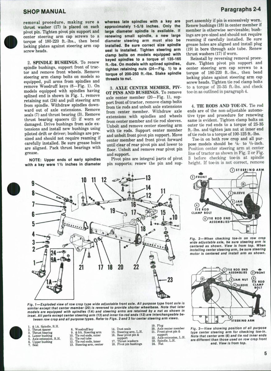
removal procedure, making sure a
thrust washer (17) is placed on each
pivot pin. Tighten pivot pin support and
center steering arm cap screws to a
torque of 180-220 ft.-lbs., then bend
locking plates against steering arm cap
screw heads.
2. SPINDLE BUSHINGS. To renew
spindle bushings, support front of trac-
tor and remove front wheels. Remove
steering arm clamp bolts on models so
equipped, pull arms from spindles and
remove Woodruff keys (8—Fig. 1). On
models equipped with spindles having
splined end is shown in F'ig. 1, remove
retaining nut (24) and pull steering arm
from spindle. Withdraw spindles down-
ward out of axle extensions. Remove
seals (7) and thrust bearing (3). Remove
thrust bearing spacers (2) if worn or
damaged. Drive bushings from axle ex-
tensions and install new bushings using
piloted drift or driver; bushings are pre-
sized and should not require reaming if
carefully installed. Be sure grease holes
are aligned. Pack thrust bearings with
grease.
NOTE: Upper ends of early spindles
with a key were 1^^ inches in diameter
whereas late spindles with a key are
approximately 1-5/8 inches. Only the
large diameter spindle is available. If
renewing small spindle, a itew large
diameter steering arm must aiso be
installed. Be sure correct size splndie
seal is installed. Tighten steering arm
clamp bolts on models equipped with
keyed spindles to a torque of 135-165
ft.-ibs. On models with splined spindles,
tighten retaining nuts (24—Fig. 1) to a
torque of 200-250 ft.-lbs. Stake spindle
threads to nut.
3. AXLE CENTER MEMBER, PIV-
OT PINS AND BUSHINGS. To remove
axle center member (20—Fig. 1), sup-
port front of tractor, remove clamp bolts
from tie rods and unbolt axle extensions
from center member. Withdraw axle
extensions with spindles and wheels
from center member and tie rod sleeves.
Unbolt and remove center steering arm
with tie rods. Support center member
and unbolt front pivot pin support. Move
center member and front pivot forward
until clear of rear pivot pin and lower to
floor. Unbolt and remove rear pivot pin
and support.
Pivot pins are integral parts of pivot
pin supports; renew the pin and sup-
Paragraphs 2-4
port assembly if pin is excessively worn.
Renew bushings (18) in center member if
member is otherwise serviceable; bush-
ings are pre-sized and should not require
reaming if carefully installed. Be sure
grease holes are aligned and install plug
(19) in bore through axle tube. Renew
thrust washers (17) if worn.
Reinstall by reversing removal proce-
dure. Tighten pivot pin support and
center steering arm cap screws to a
torque of 180-220 ft.-lbs., then bend
locking plates against steering arm cap
screw heads. Tighten tie rod clamp bolts
to a torque of 25-35 ft.-lbs. and check
toe-in as outlined in paragraph 4.
4. TIE RODS AND TOE-IN. Tie rod
ends are of the non-adjustable automo-
tive type and procedure for renewing
same is evident. Tighten clamp bolts on
outer tie rod ends to a torque of 25-35
ft.-lbs. and tighten jam nut at inner end
of tie rods to a torque of 100-125 ft.-lbs.
Toe-in on both row crop and all pur-
pose models should be V4- to V2-inch.
Position center steering arm at center
line of tractor as shown in Fig. 2 or Fig.
3 before checking toe-in at spindle
height. If toe-in is not correct, remove
1. &1A. Spindle, R.H.
2. Thrust spacer
3. Thrust bearing
4. Lower bushing
5. Axle extension, R.H.
3. Upper bushing
7. Seal
8. Woodruff key
9. & 9A. Steering arm
10. Tie rod ends, outer
11. Tie rod tube
12. Tie rod ends, inner
13. Steering arm, center
14. Dust seals
15. Steering arm, L.H.
16. Rear pivot pin &
support
17. Thrust washers
18. Pivot pin bushings
19. Plug
20. Axle center member
21. Front pivot pin &
support
22. Axle extension, L.H.
23. Spindle, L.H.
24. Nut
Fig. 2—When checking toe-in on row crop
wide adjustable axle, be sure steering arm is
centered as shown. View is from top. When
installing center steering arm, be sure steering
motor is centered and instaii arm as shown.
iPtONT
Fig. 1—Expioded view of row crop type wide adjustabie front axle. All purpose type front axle is
simitar except that center member (20) is reversed to provide shorter wheeibase. Note that iater
modeis are equipped with spindles (lA) and steering arms are retained by a nut as shown in
inset. All parts except center steering arm {13) and inner tie-rod ends {12) are interchangeable be-
tween row crop and aii purpose types. Refer to Figs, 2 and 3 for center steering arm views.
Fig. 3—View showing position of aii purpose
type center steering arm for checking toe-in.
Note that center arm (6) and tie rod inner ends
are different than those used on row crop front
end. View is from top.
Paragraphs 5-6
clamp bolts and loosen jam nuts on both
tie rods, then turn each tie rod sleeve an
equal amount as necessary. Refer to
preceding paragraph for tightening
torques.
TRICYCLE FRONT SPINDLE
5. The dual wheel tricycle spindle is
bolted directly to the power steering
motor shaft; procedure for removing and
installing spindle is obvious. Tighten
spindle to steering motor shaft cap
screws to a torque of 209-231 ft.-lbs.
Spindle can be installed on steering
motor shaft in one position only due to
offset bolt holes.
FRONT SUPPORT (PEDESTAL)
6. To remove front support, first
10
remove steering motor assembly as
outlined in paragraph 22. Remove wide
front axle assembly as outlined in
paragraph 1. Unbolt and remove side
plates from front support and trans-
mission. Attach hoist to front support,
then unbolt front support from engine
cylinder block and oil pan; be careful not
to lose shims on the two oil pan bolts and
label shims for reinstallation, if same
pedestal, oil pan and cylinder block are
to be reinstalled.
If front support, oil pan, and/or
engine cylinder block have been re-
newed, it will be necessary to select
shim thickness for installing front
support as follows: Install the three bolts
and one cap screw retaining front
support to cylinder block and tighten to
a torque of 180-220 ft.-lbs. Install the
two cap screws retaining front support
12
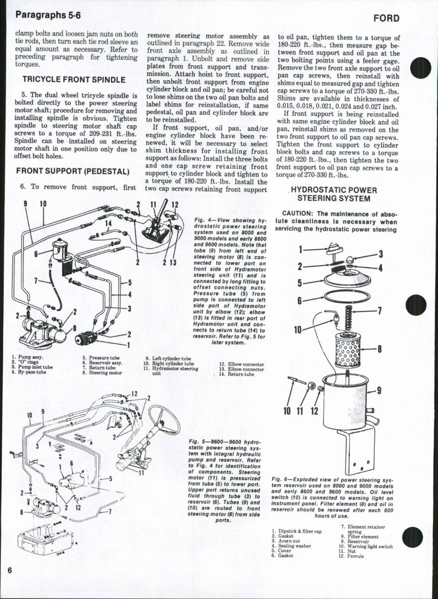
Fig. 4—View showing hy-
drostatic power steering
system used on 8000 and
9000 modeis and early 8600
and 9600 models. Note that
tube {9) from ieft end of
steering motor (8) is con-
nected to iower port on
front side of Hydramotor
steering unit {11) and is
connected by iong fitting to
offset connecting nuts.
Pressure tube (5) from
pump is connected to ieft
side port of Hydramotor
unit by eibow {12); eibow
{13) is fitted in rear port of
Hydramotor unit and con-
nects to return tube {14) to
reservoir. Refer to Fig, 5 for
iater system.
1. Pump assy.
2. "0" rings
3. Pump inlet tube
4. By pass tube
5. Pressure tube
6. Reservoir assy.
7. Return tube
8. Steering motor
9. Left cylinder tube
10. Right cylinder tube
11. Hydramotor steering
unit
12. Elbow connector
13. Elbow connector
14. Return tube
Fig. 5—8600—9600 hydro-
static power steering sys-
tem with integrai hydrauiic
pump and reservoir. Refer
to Fig. 4 for identification
of components. Steering
motor {11) is pressurized
from tube (5) fo iower port.
Upper port returns unused
fluid through tube (3) to
reservoir (6). Tubes (9) and
{10) are routed to front
steering motor {8) from side
ports.
FORD
to oil pan, tighten them to a torque of
180-220 ft.-lbs., then measure gap be-
tween front support and oil pan at the
two bolting points using a feeler gage.
Remove the two front axle support to oil
pan cap screws, then reinstall with
shims equal to measured gap and tighten
cap screws to a torque of 270-330 ft.-lbs.
Shims are available in thicknesses of
0.015, 0.018, 0.021, 0.024 and 0.027 inch.
If front support is being reinstalled
with same engine cylinder block and oil
pan, reinstall shims as removed on the
two front support to oil pan cap screws.
Tighten the front support to cylinder
block bolts and cap screws to a torque
of 180-220 ft.-lbs., then tighten the two
front support to oil pan cap screws to a
torque of 270-330 ft.-lbs.
HYDROSTATIC POWER
STEERING SYSTEM
CAUTION: The maintenance of abso-
iute cleanliness is necessary when
servicing the hydrostatic power steering
Fig. 6—Exploded view of power steering sys-
tem reservoir used on 8000 and 9000 modeis
and early 8600 and 9600 modeis. Oil level
switch {10) is connected to warning iight on
instrument panel. Fitter element (8) and oil in
reservoir shouid be renewed after each 600
hours of use.
1. Dipstick & niter cap
2. Gasket
3. Acorn nut
4. Sealing washer
5. Cover
6. Gasket
7. Element retainer
spring
8. Filter element
9. Reservoir
10. Warning light switch
11. Nut
12. Ferrule
SHOP MANUAL
Paragraphs 7-9
system. Avoid use of shop towels or rags
In wiping internal parts as any lint can
cause malfunction of the system.
All 8000 and 9000 models and early
8600 and 9600 models were equipped
with a remote power steering oil reser-
voir, a Saginaw Hydramotor power
steering motor and a power steering
pump with a flow control valve. The
relief valve on pump is accessible from
the outside.
Late 8600 and 9600 models were
equipped with a Ross power steering
motor which uses a spool to control flow.
Steering pumps on these models have
the reservoir as an integral part of
pump. It is necessary to remove this
type pump from engine to change filter
or relief pressure.
7. FLUID, BLEEDING AND SYS-
TEM RESERVOIR. Recommended
power steering fluid is Ford M-2C-41
oil. Maintain fluid level to full mark on
dipstick. A low oil level switch assembly
(10—Fig. 6) is used on models with
remote fluid reservoir and is connected
to a warning light on instrument panel.
The light (located in Proof-Meter dial)
should be on when starter switch is
turned to "ON" position and go out when
engine is started. If light remains on
after engine is started, check for low oil
level or malfunction in warning light
system.
After each 600 hours of use, renew
filter element. On models with remote
reservoir, remove all oil from reservoir
with suction gun, install new element
and refill reservoir with new oil. On
models with integral reservoir, remove
pump from engine, drain reservoir,
remove bolt (1—Fig. 8) and renew filter
and "0" rings.
On all models the power steering
system is self-bleeding. When any unit
has been removed or disconnected, refill
reservoir, start engine and cycle system
by turning steering wheel from lock to
lock. System is fully bled when front
wheels respond directly to steering
wheel movement and oil stays at level
mark. Check fluid level and add oil as
required to maintain full reservoir when
cycling system.
8. CHECKING SYSTEM PRES-
SURE. On models with remote reser-
voir the power steering pump assembly
incorporates a pressure relief valve and
a flow control valve. System relief
pressure should be 1450-1550 psi. On
later models with integral pump and
reservoir, pressure should be 1550-1650
psi.
To check system relief pressure, dis-
connect fitting and remove elbow in
pressure line (5—Fig. 4 or Fig. 5) and
connect a 0-2000 psi gage to pump, using
an "0" ring on fitting to pump. With the
engine running, gage reading should be
as stated above. On models with remote
reservoir, if pressure is not as specified,
remove the pressure relief valve cap
(7—Fig. 7) and add or remove shims (6)
as required. If adding shims under the
pressure relief valve cap will ndt
increase system pressure, clean flow
control spool in pump. If pressure is still
low remove and overhaul power steering
pump as outlined in paragraph 11.
CAUTION: When checking system
reiief pressure, run engine only long
enough to observe gage reading; pump
may be damaged if engine is aiiowed to
run for an excessive length of time.
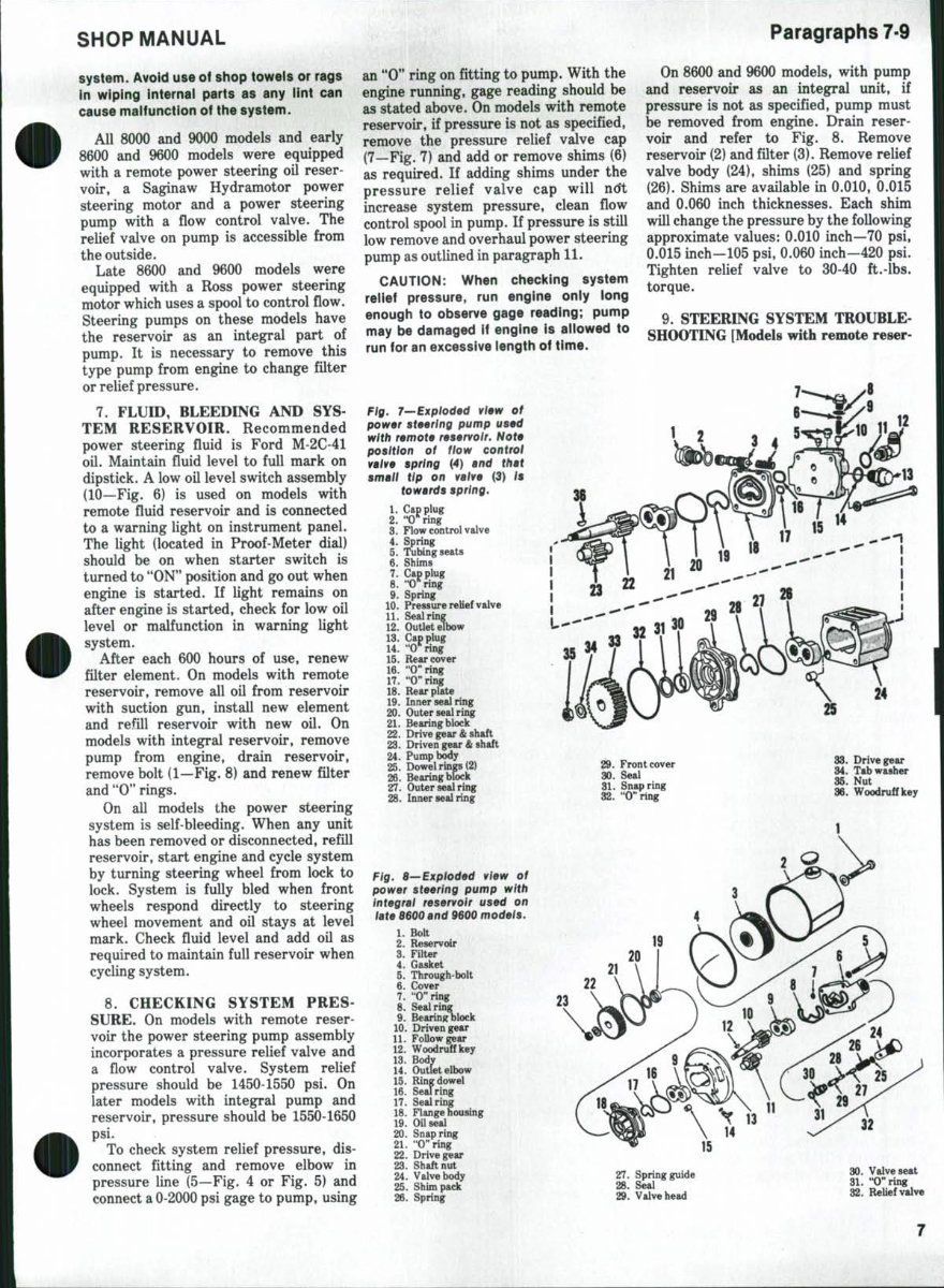
Fig, 7—Exploded view of
power steering pump used
with remote reservoir. Note
position of flow control
valve spring (4) and that
small tip on vaive {3) Is
towards spring.
On 8600 and 9600 models, with pump
and reservoir as an integral unit, if
pressure is not as specified, pump must
be removed from engine. Drain reser-
voir and refer to Fig. 8. Remove
reservoir (2) and filter (3). Remove relief
valve body (24), shims (25) and spring
(26). Shims are available in 0.010, 0.015
and 0.060 inch thicknesses. Each shim
will change the pressure by the following
approximate values: 0.010 inch—70 psi,
0.015 inch—105 psi, 0.060 inch—420 psi.
Tighten relief valve to 30-40 ft.-lbs.
torque.
9. STEERING SYSTEM TROUBLE-
SHOOTING [Models with remote reser-
12
Cap plug
"O*^ring
12
13.
14.
15.
16.
17.
18.
19.
2. Oring
3. Flow control valve
4. Spring
5. Tubing seats
6. Shims
7. Cap plug
8. •t)*^ring
9. Spring
10. Pressure relief valve
11. Seal ring
12. Outlet elbow
Cap plug
"O*ring
Rear cover
"O"ring
"O"ring
Rear plate
19. Inner seal ring
20. Outer seal ring
21. Bearing block
22. Drive gear & shaft
23. Driven gear & shaft
24. Pump body
25. Dowel rings (2)
26. Bearing block
27. Outer seal ring
28. Inner seal ring
Fig. 8—Exploded view of
power steering pump with
integrai reservoir used on
iate 8600 and 9600 modeis.
1. Bolt
2. Reservoir
3. Filter
4. Gasket
5. Through bolt
6. Cover
7. "O^'ring
8. Seal ring
9. Bearing block
10. Driven gear
11. Follow gear
12. Woodruff key
13. Body
14. Outlet elbow
15. Ring dowel
16. Sealring
17. Sealring
18. Flange housing
19. Oil seal
20. Snap ring
21. "O"ring
22. Drive gear
23. Shaft nut
24. Valve body
25. Shim pack
26. Spring
29. Front cover
30. Seal
31. Snap ring
32. "O"ring
24
33. Drive gear
34. Tab washer
35. Nut
36. Woodruff key
27. Spring guide
28. Sial
29. Valve head
32
30. Valve seat
31. "Chng
32. Relief valve
Paragraphs 10-12
FORD
voir). Refer to the following paragraphs
for checking causes of steering system
malfunction:
HARD STEERING. Check column
bearings and bearings in Hydramotor
unit; renew if rough or damaged. Check
ring, rotor and vanes for wear and
renew the assembly if necessary. Check
for sticking control valve spool or
blocking spool in Hydramotor; clean
valves or renew Hydramotor parts as
required.
EXCESSIVE WHEEL DRIFT. Check
blocking spool spring and guide assem-
bly and renew if spring is broken. Check
for leakage past blocking valve; if exces-
sive, renew valve body housing assem-
bly. Check seals on steering cylinder
pistons and renew pistons and/or
cylinders as required.
STEERING WHEEL TURNING UN-
AIDED. Check the Hydramotor unit for
sticking control valve spool, broken
valve spool spring, actuator shaft
binding or torque shaft (inside actuator
shaft) broken. Clean spool and bore or
renew valve body housing assembly as
required.
STEERING WHEEL SLIPPAGE.
Hydramotor control valve spool scored
(renew valve body housing assembly) or
rotor seals leaking (renew seals).
EXCESSIVE NOISE. Hydraulic lines
vibrating against tractor frame or
broken control valve spool spring;
insulate lines from tractor or renew
valve body housing assembly if spring is
broken.
ERRATIC MOVEMENT OF FRONT
WHEELS. Check Hydramotor ring,
rotor or vanes for scoring, wear or
binding condition; renew the ring and
rotor assembly if necessary.
WILL NOT STEER IN EITHER
DIRECTION. The manual steer check
ball between pump return and pressure
passages in Hydramotor unit may not be
seating. Disassemble unit and clean
passage with solvent and dry with
compressed air. Renew pressure plate
assembly if check ball cannot be made to
seat.
FRONT WHEELS JERK OR TURN
WITHOUT MOVING STEERING
WHEEL. Check for sticking rotor vanes,
rotor springs out of place or broken,
scored pressure plate, scored rotor ring,
scored housing, ball check valves in
pressure plate leaking, improper assem-
bly causing gap between rotor compo-
nents. Disassemble the Hydramotor
unit, carefully clean and inspect all parts
and renew components as necessary.
10. STEERING SYSTEM TROU-
BLESHOOTING. (Models with integral
pump and reservoir). Refer to the fol-
lowing paragraphs for checking causes of
steering system malfunction:
HARD STEERING. Check column
bearings and bearings in steering
motor; renew if rough or damaged.
Check rotor and stator assembly for
wear or damage and renew assembly if
necessary. Check for leaks from dam-
aged valve spool; renew steering motor
if spool is damaged. Check for binding at
all pivot points in steering; free up and
lubricate as necessary. Check for
jammed valve spool; if unable to free up,
renew steering motor assembly.
EXCESSIVE WHEEL DRIFT. Check
for leakage past valve spool; if spool is
worn or damaged, renew spool assem-
bly.
EXCESSIVE NOISE. Hydraulic lines
vibrating against tractor frame. Insulate
lines from tractor.
ERRATIC WHEEL MOTION. Rotor
vanes sticking or damaged. Check
vanes, rotor and stator for free
movement; renew if necessary.
WHEELS JERK FROM STOP TO-
STOP. Rotor vane springs jammed;
check for proper seating of vane springs,
renew complete assembly if damaged.
11. R&R AND OVERHAUL PUMP.
(REMOTE RESERVOIR). Thoroughly
clean pump, lines and surrounding area.
Disconnect lines from pump and allow
fluid to drain. Cap all openings to pre-
vent dirt from entering pump or lines,
then unbolt and remove pump assem-
bly from engine front plate. When rein-
stalling pump, use new sealing "0" ring
and tighten retaining bolts to a torque of
23-30 ft.-lbs. Reconnect lines, fill and
bleed system as in paragraph 7.
Refer to exploded view of remote
reservoir model pump in Fig. 7 and dis-
assemble pump as follows: Scribe an
assembly mark across pump covers and
body. Straighten tab on washer (34) and
remove nut (35). Pull drive gear (33)
from pump shaft and remove key (36).
Remove the four through-bolts and
separate rear cover assembly (15),
plate (18), body (24) and front cover
(29). Remove bearing blocks (21 and 26)
and gears (22 and 23) from pump as a
unit. Remove caps (1, 7 and 13) from
rear cover (15) and withdraw flow
control valve (3), pressure relief valve
(10) and related parts. Remove locating
snap ring (31) and the oil seal (30) from
front cover. Clean all parts in a suitable
solvent, air dry, then lightly oil all
machined surfaces.
Inspect bearing blocks (21 and 26) for
signs of seizure or scoring on face of
journals. (When disassembling bearing
block and gear unit, keep parts in
relative position to facilitate reassem-
bly). Light score marks on faces of
bearing blocks can be removed by
lapping bearing block on a surface plate
using grade "0" emery paper and
kerosene. Examine body for wear in
gear running track. If track is worn
deeper than 0.0025 inch on inlet side,
body must be renewed. Examine pump
for excessive wear or damage on
journals, journal bores in bearing blocks
or teeth. Runout across the gear face to
gear tooth edge should not exceed 0.001
inch. If necessary, the gear journals may
be lightly polished with grade "0" emery
paper to remove wear marks. The gear
faces may be polished by sandwiching
grade "0" emery paper between gear
and face of scrap bearing block, then
rotating the gear. New gears are avail-
able in matched sets only. If flow control
valve (3) or rear cover (15) are scored or
damaged, they must be renewed as a
matched set only.
When reassembling pump, install all
new seals, "0" rings and sealing rings.
Insert new drive shaft oil seal (30) in
front plate and install locating snap ring.
Install flow control valve (3), spring (4)
and plugs (1 and 13) with new "0" rings
(2 and 14). Install pressure relief valve
(10), spring (9) and plug (7), being sure
that all shims (6) are in plug and using
new "0" ring (8). Assemble pump gears
to bearing blocks and insert the unit into
pump body. Be sure the two bolt rings
(hollow dowels) are in place in pump
body, then position the front cover on
body. Place the rear plate (18) at rear of
body and install rear cover. Tighten the
four cap screws (through-bolts) to a
torque of 13-17 ft.-lbs. Install the pump
drive gear key, drive gear, tab washer
and nut. Tighten the nut to a torque of
55-60 ft.-lbs. and bend tab of washer
against flat on nut.
12. R&R AND OVERHAUL INTE-
GRAL RESERVOIR PUMP. For ex
ploded view of parts used on models with
integral pump and reservoir refer to Fig.
8. Clean pump and surrounding area and
disconnect pump pressure and return
lines. Remove the two cap screws
securing pump to engine front cover and
lift off pump and reservoir as a unit.
Drain the reservoir and remove
through-bolt (1), reservoir (2) and filter
(3).
Relief valve cartridge (32) can now be
removed if service is indicated. For ac-
8
SHOP MAMUAL
Paragraphs 13-16
cess to shims (25) grasp seat (30) lightly
in a protected vise and unscrew
body (24). Shims (25) are available in
thicknesses of 0.010, 0.015 and 0.060
inch. Starting with the removed shim
pack substitute shims, thus varying total
pack thickness, to adjust opening
pressure. Available shims permit thick-
ness adjustment in increments of 0.005
inch and each 0.005 inch in shim pack
thickness will change opening pressure
about 35 psi. If parts are renewed, the
correct thickness can only be determined
by trial and error, using the removed
shim pack as a guide.
To disassemble the pump, bend back
tab washer and remove shaft nut (23),
drive gear (22) and key (12). Mark or
note relative positions of flange housing
(18), pump body (13) and cover (6); then
remove pump through bolts (5). Keep
parts in their proper relative position
when disassembling pump unit. Pump
gears (10 and 11) are available in a
matched set only. Bearing blocks (9) are
available separately but should be
renewed in pairs if renewal is because of
wear. Bearing blocks should also be
renewed with gear set if any shaft or
bore wear is evident. Examine body (13)
for wear in gear running track. If track
is worn deeper than 0.025 inch on inlet
side, body must be renewed. Renew all
"0" rings and seals.
When reassembling the pump, tighten
through bolts (5) to a torque of 25 ft.-lbs.
and drive gear nut (23) and relief valve
body (24) to a torque of 30-40 ft.-lbs.
13. SAGINAW HYDRAMOTOR
STEERING UNIT. Refer to the follow-
ing paragraphs 14 through 18 for
information on removal, overhaul and
installation of the Saginaw Hydramotor
steering unit which is used on 8000 and
9000 models and early 8600 and 9600
models. If parts are not available for
repair of Hydramotor unit, a conversion
kit is available to install the later Ross
unit on early tractors. Refer to para-
graph 9 for troubleshooting information.
For the Ross unit used on 8600 and 9600
models, refer to paragraphs 19, 20 and
21.
14. R&R HYDRAMOTOR UNIT.
To remove Hydramotor, first remove
hood top, right and left side panels, then
proceed as follows:
Remove cap (1—Fig. 9) from adjuster
knob (4) and remove nut (2) and washer
(3). Knob can then be removed from
locking rod in shaft (11), then remove
steering wheel (7) and shaft (8) as an
assembly. Disconnect the four tubes
from Hydramotor unit, then cap or plug
all openings. Loosen both jam nuts (24)
and unscrew the pivot studs (23) from
support (21). Then remove steering unit
from below the instrument panel.
NOTE: Remove intake manifold air
tube if necessary for ciearance.
To reinstall, position unit in support
with tilt quadrant engaged in lock
plunger and turn pivot studs in to
support unit. Reconnect the four tubes
and reinstall steering wheel and adjuster
knob. With steering shaft shortened to
fuU extent and steering wheel in lowered
position, attach pull scale to steering
wheel rim and release quadrant latch.
Tighten pivot studs until a pull of 18-22
pounds will lift steering wheel from
lowered position, then tighten jam nuts
to a torque of 180-220 ft.-lbs. and
recheck pivot stud adjustment.
NOTE: Do not attempt to position
steering wheei on shaft as slippage in
unit will not allow wheei to remain in any
relative position to front wheel move-
ment.
R&R STEERING COLUMN
JACKET AND SHAFT ASSEMBLIES
(Hydramotor Models). With Hydra-
motor unit removed as outlined in para-
graph 14, proceed as follows:
Loosen clamp (15—Fig. 9) and pull
column jacket assembly (10) from control
valve housing (16). Unscrew the hex nut
(14) until it nearly contacts control valve
housing. Nut was staked when assem-
bled and will turn hard. Drive the
tapered collar (13) towards nut until
collar is loose, then turn collar untO hole
in collar is over locking ball hole in outer
shaft (11) and shake the ball (12) out
of hole. The outer shaft, tapered collar
and hex nut can then be removed from
the Hydramotor actuator shaft.
Reassemble the unit before rein-
stalling on actuator shaft as follows: In-
stall tapered ring (13) on outer shaft
(11), with large I.D. first. Install a new
nut (14) just far enough to catch one or
two threads of outer shaft. Engage
splines of outer shaft on splines of
actuator shaft. Align hole in tapered
ring, hole in outer shaft and groove
around the actuator shaft, then drop
locking ball in hole and groove and turn
tapered collar V4-turn. Tighten the hex
nut to a torque of 40-50 ft.-lbs. and stake
nut into slot in outer shaft as shown in
Fig. 11.
16. R&R BLOCKING SPOOL (RE-
ACTION) VALVE (Hydramotor Mod-
els). The blocking spool valve and
related parts can be removed and rein-
stalled after the Hydramotor steering
unit has been removed as outlined in
paragraph 14. Refer to Fig. 12 and
proceed as follows:
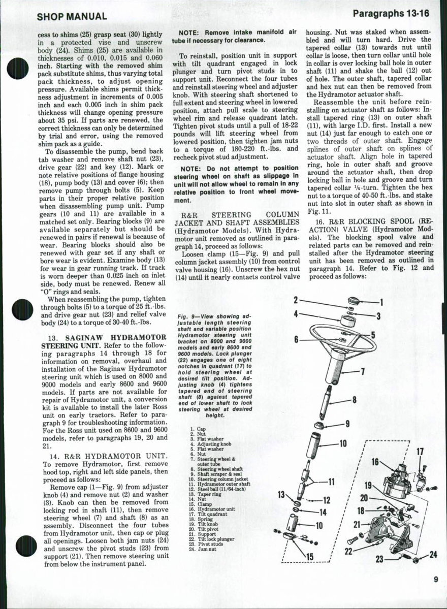
Fig. 9—View showing ad-
justable length steering
shaft and variable position
Hydramotor steering unit
bracket on 8000 and 9000
models and early 8600 and
9600 models. Lock plunger
{22) engages one of eight
notches in quadrant (f 7) to
hold steering wheel at
desired tiit position. Ad-
justing knob (4) tightens
tapered end of steering
shaft {8) against tapered
end of tower shaft to lock
steering wheei at desired
height.
1. Cap
2. Nut
3. Flat washer
4. Adjusting knob
5. Flat washer
6. Nut
7. Steering wheel &
outer tube
8. Steering wheel shaft
9. Shaft scraper & seal
10. Steering column jacket
11. Hydramotor outer shaft
12. Steel ball (11/64-inch)
13. Taper ring
14. Nut
15. Clamp
16. Hydramotor unit
17. Tilt quadrant
18. Spring
19. Tilt knob
20. Tilt pivot
21. Support
22. Tilt lock plunger
23. Pivot studs
24. Jam nut
You're Reading a Preview
What's Included?
Fast Download Speeds
Online & Offline Access
Access PDF Contents & Bookmarks
Full Search Facility
Print one or all pages of your manual
$27.99
Viewed 92 Times Today


Secure transaction
What's Included?
Fast Download Speeds
Online & Offline Access
Access PDF Contents & Bookmarks
Full Search Facility
Print one or all pages of your manual
$27.99
Get access to the comprehensive repair manual for Ford 1000, 1600, 8000, 8600, 9000, 9600, 9700, Tw10-20-30 models. This manual is an invaluable resource for both professional mechanics and DIY enthusiasts. It provides detailed technical specifications, step-by-step instructions, and illustrations to guide you through maintenance, repair, and troubleshooting procedures.
Whether you're working on engine overhauls, electrical systems, hydraulics, or any other aspect of these Ford models, this manual equips you with the knowledge and confidence to tackle the task at hand. With its clear and concise information, you can efficiently perform repairs and keep your Ford tractor in optimal working condition.


