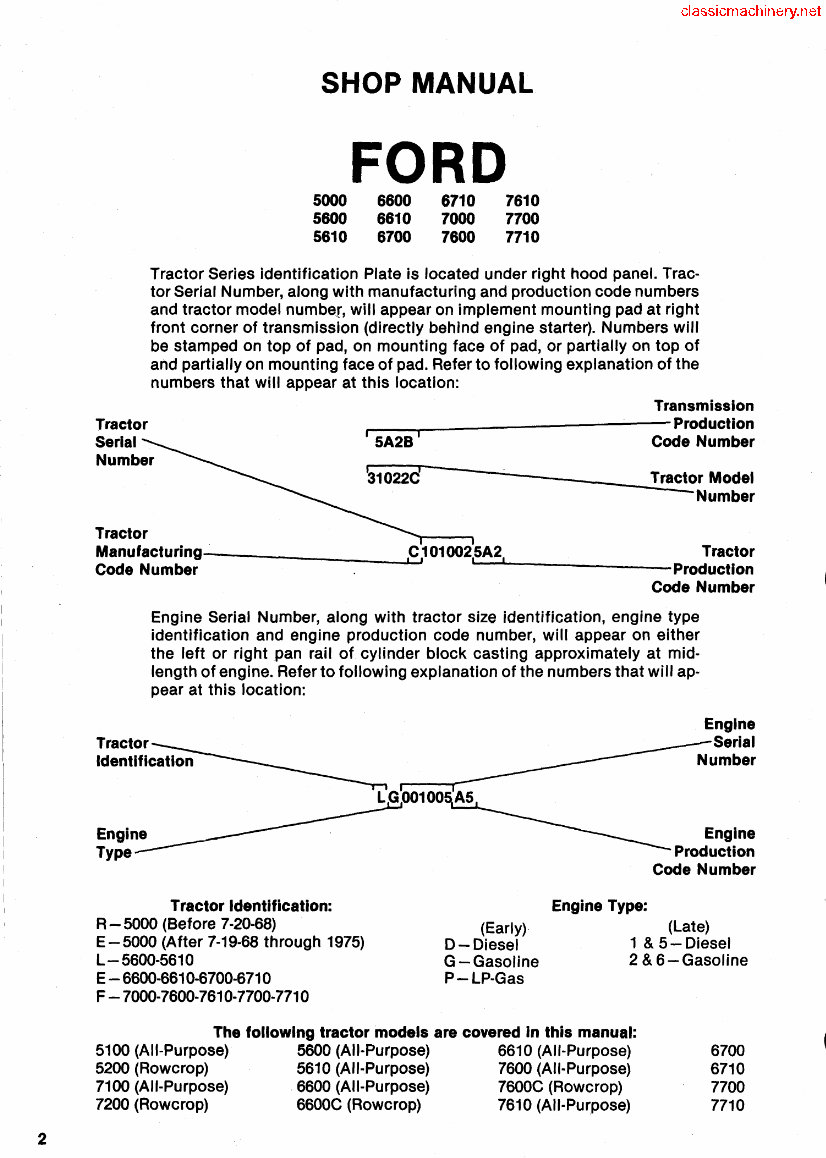
2 SHOP MANUAL 5000 5800 5810 FORD 8800 8810 8700 6710 7000 7800 7610 7700 7710 Tractor Series identification Plate is located under right hood panel. Trac- tor Serial Number, along with manufacturing and production code numbers and tractor model number, will appear on implement mounting pad at right front corner of transmission (directly behind engine starter). Numbers will be stamped on top of pad, on mounting face of pad, or partially on top of and partially on mounting face of pad. Refer to following explanation of the numbers that will appear at this location: Tractor Serial Number Transmission r--__ ------------Production i 5A2B I Code Number 33V10~2~2~Cr' ------~------______ _1T~~~c~torModel -Number Tractor Manufacturing--_______ --i.,c::..,1 01 002,5A2, Tractor Code Number - .... r.---------Production Code Number Engine Serial Number, along with tractor size identification, engine type identification and engine production code number, will appear on either the left or right pan rail of cylinder block casting approximately at mid· length of engine. Refer to following explanation of the numbers that will ap· pear at this location: Tractor Identification: R - 5000 (Before 7·20·68) E - 5000 (After 7·19·68 through 1975) L - 5600·5610 E - 6600-6610·6700·6710 F -7000·7600·7610·7700·7710 (Early) D-Diesel G-Gasoline P-LP·Gas Engine Type: Engine Serial Number Engine Production Code Number (Late) 1 & 5-Diesel 2 & 6-Gasoline The following tractor models are covered in this manual: 5100 (All-Purpose) 5600 (AII·Purpose) 6610 (AII·Purpose) 6700 5200 (Rowcrop) 5610 (All-Purpose) 7600 (AII·Purpose) 6710 7100 (AII·Purpose) .6600 (All-Purpose) 7600e (Rowcrop) 7700 7200 (Rowcrop) 6600e (Rowcrop) 7610 (AII·Purpose) 7710
INDEX (By Starting Paragraph) BELT PULLEY ................................. 285 Valve Adjustment ............................... 78 BRAKES .................................. 264,265 Valves & Seats ................................. 76 Transmission Hand Brake ....................... 268 Valve Guides & Springs ............ " .............. 77 CAB ....................................... 414, 415 FINAL DRIVE GEARS ............. ~ ............ 263 CARBURETOR ................................. 113 FRONT AXLE .............................. 1,22,45 CLUTCH ...................................... 164 FRONT-WHEEL DRIVE ..................... 55A, 56 CLUTCH, PTO .............................. 280,281 GOVERNOR: COOLING SYSTEM: Diesel .................................... 141,142 Radiator ...................................... 148 Non-Diesel .................................... 145 Thermostat ................................... 147 HYDRAULIC LIFT SYSTEM: Water Pump .................................. 150 Adjustments .................................. 294 DIESEL FUEL SYSTEM: Cooler By-Pass Valve ........................... 289 Bleeding ...................................... 123 De-Luxe Control Valves ........................ .409 Filters ...................... " ................. 122 Filters ................................... 287, 288 Injection Pump ............................ 132, 137 Lift Cover, R&R ....................... 354,355,356 Injector Nozzles ................................ 124 Lift Cylinder, Overhaul ...................... 358, 369 Thermostat ................................... 144 Load Monitor, R&R ............................ 370 Troubleshooting ............................... 114 Pressure Check ................................ 293 DIFFERENTIAL ............................... 257 Priority Valve ................................. 385 DIFFERENTIAL LOCK ......................... 261 Pump ........................................ 379 ELECTRICAL SYSTEM: Remote Control Valves .......................... 389 Alternator & Regulator ......... " ................ 152 Selector Valve ................................. 361 Generator & Regulator ......................... ~ 151 Troubleshooting ............................... 292 Ignition Distributor ............................. 160 " IGNITION SYSTEM ............................. 157 Starting Motor ............................ 155, 156 POWER STEERING: ENGINE: Bleed System ....................... 13,31,40, 51, 67 Assembly, R&R ................................. 72 Camshaft ...................................... 90 - Connecting Rod Bearings ......................... 98 Control Valve .................................. 16 Pump ., ................................. 15, 34, 53 Steering Gear ................................ 5, 10 Crankshaft Bearings ............................. 99 Steering Motor '" ........................ 28, 44, 55 Crankshaft Oil Seals ............................ 100 System Pressure .......................... 14, 41, 52 Cylinder Head ..... .' ............................ 74 With FWD ............................. 55K, 65, 66 Cylinders ...................................... 94 POWER TAKE-OFF ............................. 271 Engine Balancer ............................... 103 REAR AXLE: Flywheel, R&R ................................ 104 Axle Housings ................................. 262 Oil Pan ....................................... 105 Bearing Adjustment ............................ 263 Oil Pump ..................................... 106 Shaft, R&R ................................... 262 Pistons & Rings .............................. 92, 93 Reduction Gear ................................ 251 Piston & Rod Removal ........................... 91 STEERING GEAR (Manual) ........................ 5 Piston Pins ..................................... 97 TRANSMISSION: Rocker Arms ................................... 82 Dual Power ................................... 171 Timing Gear Cover .............................. 83 8-speed (Non-Synchromesh) ...................... 177 Timing Gear .................................... 85 8-speed (Synchromesh) .......................... 186 Turbocharger ................................. 107 Select-O-Speed ................................ 196 DUAL DIMENSIONS This service manual provides specifications in both the U.S. Customary and Metric (SI) systems of measurement. The first specification is given in the measuring system per- ceived by us to be the preferred system when servicing a particular component, while the second specification (given in parenthesis) is the converted measurement. For instance, a specification of "0.011 inch (0.28 mm)" would indicate that we feel the preferred measure- ment, in this instance, is the U.S. system of measurement and the metric equivalent of 0.011 inch is 0.28 mm. 3
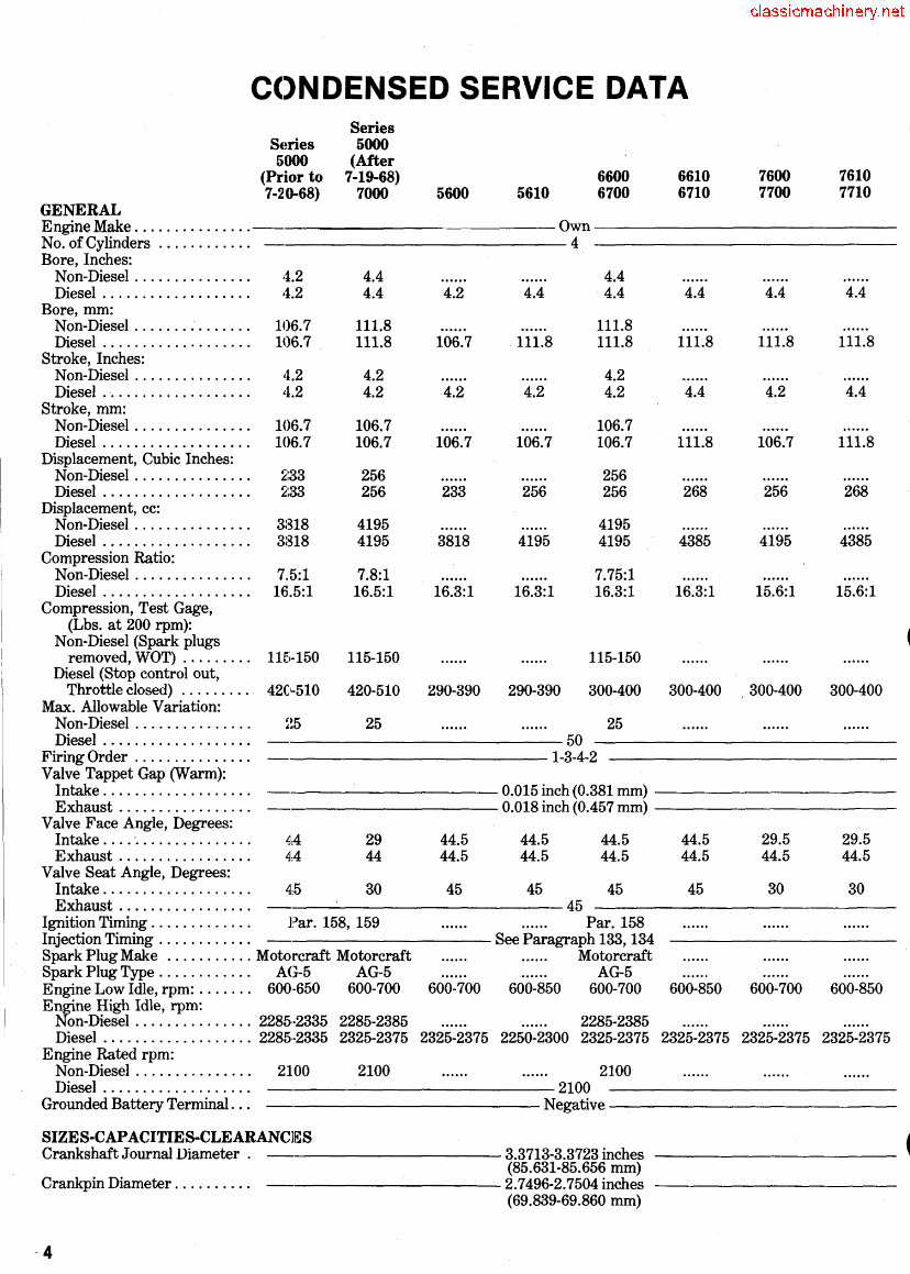
CONDENSED SERVICE DATA (CONT.) Series Series 5000 5000 (After (Prior to 7-19-68) 6600 6610 7600 7610 7-20-68) 7000 5600 5610 6700 6710 7700 7710 SIZES-CAPACITIES-CLEARANCES (Cont). Camshaft Journal Diameter ... 2.3895-2.3905 inches (60.693-60.718 mm) Piston Pin Diameter .......... See Paragraph 97 Valve Stem Diameter, Intake . 0.3711-0.3718 inch (9.425-9.443 mm) Valve Stem Diameter, Exhaust 0.3701-0.3708 inch (9.400-9.418 mm) Main Bearing Diametral Clearance ................ 0.0022-0.0045 inch (0.0559-0.1143 mm) Rod Bearing Diametral Clearance: Aluminum ............... 0.0021-0.0042 inch (0.053-0.107 mm) Copper-Lead ............. 0.0017-0.0038 inch (0.0431-0.0965 mm) Camshaft Bearing Diametral Clearance ................ 0.001-0.003 inch (0.0254-0.0762 mm) Crankshaft End Play ........ 0.004-0.008 inch (0.1016-0.2032 mm) Camshaft End Play .......... 0.001-0.007 inch (0.0254-0.1778 mm) Piston Skirt-to-Cylinder Clearance ................ - See Paragraph 96 Cooling System (Less Heater): Quarts (U.S.) ............. 15.3 15.3(1) 13.5 13.5 14.5(2) 14.5(2) 18.0(3) 18.0(3) Liters ................... 14.5 14.5 12.8 12.8 13.8 13.8 17.0 17.0 Crankcase With Filter: Quarts (U.S.) ............. 8 8(4) 9 9 9 9 9 9 Liters ................... 7.8 7.8 8.5 8.5 8.5 8.5 8.5 8.5 Transmission, 8-Speed: Quarts(U.S.) ............. 19 10.8(5) 12(6) Liters ................... 17.9 10.2 11.4 Select-O-Speed: Quarts (U.S.) ............. 11.8 11.8 Liters ................. " 11.2 11.2 Transmission & Rear Axle, Dual Power, 540 rpm pto: Quarts (U.S.)* ............ 56 56 56 56 56 56 Liters .................... 52.9 52.9 52.9 52.9 52.9 52.9 Transmission & Rear Axle, Dual Power With 2-Speed pto: Quarts (U.S.)* ............ 60 60 60 60 60 60 Liters ........... ~ ....... 56.8 56.8 56.8 56.8 56.8 56.8 Rear Axle, Less Dual Power: Quarts (U.S.) .... _ ........ 33 34.8(7) 43 Liters ................... 31.2 32.9 40.7 Steering Gear, Manual: Quarts (U.S.) ............. 0.96 Liters ................... 0.90 Power Steering: Quarts (U.S.) I • ••.••••••••• 1.87 2.35 2.3 2.3 2.3(8) 2.3(8) 2.3(8) 2.3(8) - Liters ................... 1.76 2.22 2.2 2.2 2.2 2.2 2.2 2.2 (1) Model 7000: 14.5 Qts. (13.7 L). (2) Models 6600 and 6610: 13.5 Qts. (12.8 L). (3) Models 7700 and 7710: 19 Qts. (18 L). (4) Model 7000; 9 Qts. (8.5 L). (5) Model 7000: 55 Qts_ (52 L). (6) Model 5600 w/o Dual Power. (7) Model 7000: 55 Qts. (52 L). (8) Models 6700, 6710, 7700 and 7710: 2.5 Qts. (2.4 L). *Models with front-wheel drive refer to paragraph 55N or 69 and 286. 5
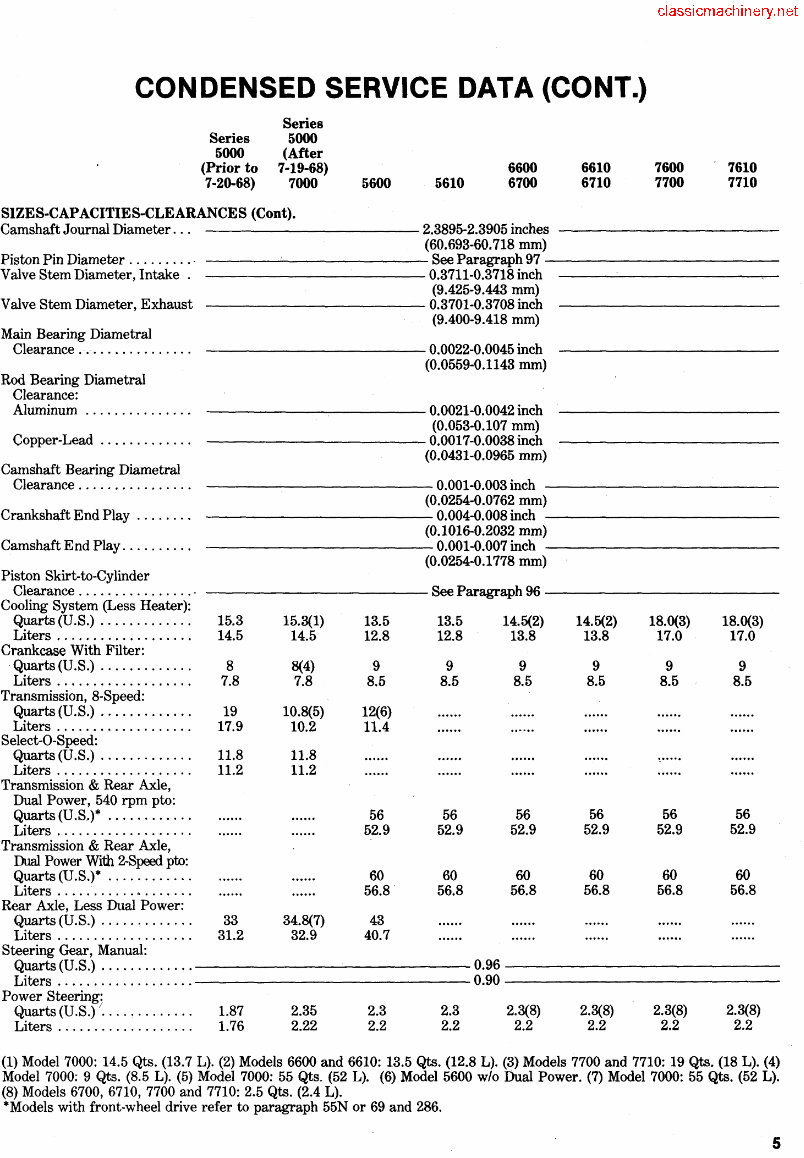
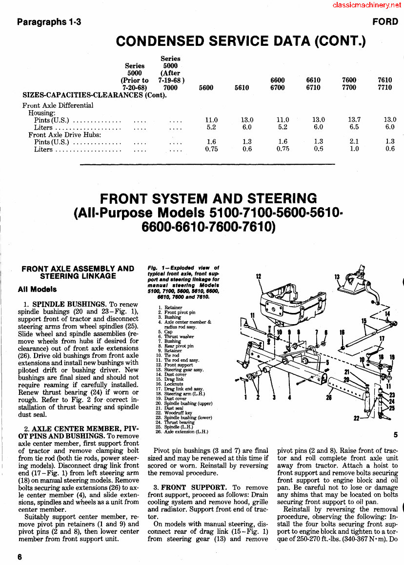
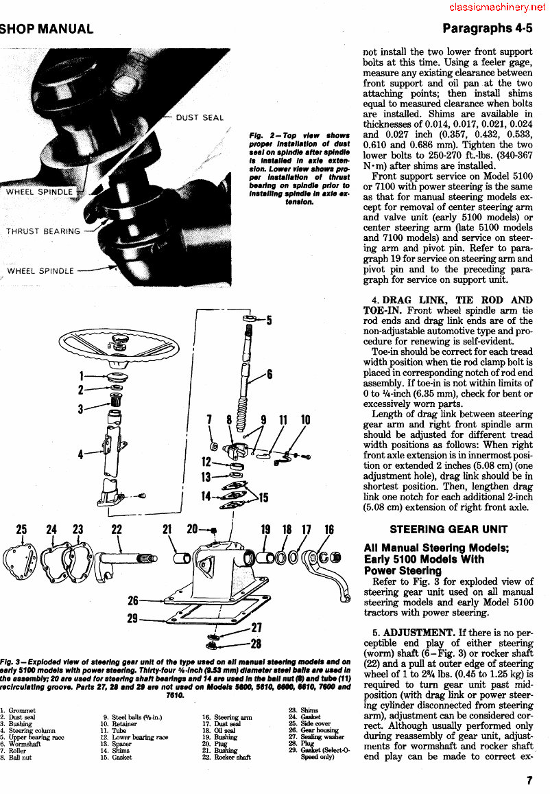
Paragraphs 1·3 FORD CONDENSED SERVICE DATA (CONT.) Series Series 5000 5000 (After (Prior to 7-19-68 ) 6600 6610 7600 7610 7-20-68) 7000 5600 5610 6700 6710 7700 7710 SIZES·CAPACITIES-CLEARANCES (Cont). Front Axle Differential Housing: Pints (U.S.) .............. 11.0 13.0 11.0 13.0 13.7 13.0 Liters ................... 5.2 6.0 5.2 6.0 6.5 6.0 Front Axle Drive Hubs: Pints (U.S.) .............. 1.6 1.3 1.6 1.3 2.1 1.3 Liters ................... 0.75 0.6 0.75 0.5 1.0 0.6 FRONT SYSTEM AND STEERING (All-Purpose Models 5100-7100-5600-5610- 6600-6610- 7600- 7610) FRONT AXLE ASSEMBLY AND STEERING LINKAGE All Models 1. SPINDLE BUSHINGS. To renew spindle bushings (20 and 23-Fig. 1), support front of tractor and disconnect steering arms from wheel spindles (25). Slide wheel and spindle assemblies (re- move wheels from hubs if desired for clearance) out of front axle extensions (26). Drive old bushings from front axle extensions and install new bushings with piloted drift or bushing driver. New bushings are final sized and should not require reaming if carefully installed. Renew thrust bearing (24) if worn or rough. Refer to Fig. 2 for correct in- stallation of thrust bearing and spindle dust seal. Fig. 1- Exploded vl.w of typical f,ont ax/., f,ont sup- port and st •• ring IInkag. fo, manual st •• ,/ng Mod.ls 5100, 7100, 5BOO, 5610, HOO, 6610, 7600 and 7610. 1. Retainer 2. Front pivot pin 3. Bushing 4. Axle center member & radius rod assy. 5. Cap 6. Thrust washer 7. Bushing 8. Rear pivot pin 9. Retainer 10. Tie rod 11. Tie rod end assy. 12. Front support 13. Steering gear assy. 14. Dust cover 15. lliaJllink 16. Locknuts 17. Drag link end assy. 18. Steering arm (L.H.) 19. Dust cover 20. Spindle bushing (upper) 21. Dust seal 22. Woodruff key 23. Spindle bushing (lower) 24. Thrust bearing 25. Spindle (L.H.) 26. Axle extension (L.H.) Pivot pin bushings (3 and 7) are final sized and may be renewed at this time if scored or worn. Reinstall by reversing the removal procedure. 5 pivot pins (2 and 8). Raise front of trac- tor and roll complete front axle unit away from tractor. Attach a hoist to front support and remove bolts securing front support to engine block and oil pan. Be careful not to lose or damage ~ 2. AXLE CENTER MEMBER, PIV- OT PINS AND BUSHINGS. To remove axle center member, first support front of tractor and remove clamping bolt from tie rod (both tie rods, power steer- ing models). Disconnect drag link front end (17 -Fig. 1) from left steering arm (18) on manual steering models. Remove bolts securing axle extensions (26) to ax- le center member (4), and slide exten- sions, spindles and wheels 'as a unit from center member. Suitably support center member, re- move pivot pin retainers (1 and 9) and pivot pins (2 and 8), then lower center member from front support unit. 3. FRONT SUPPORT. To remove front support, proceed as follows: Drain cooling system and remove hood, grille and radiator. Support front end of trac- tor. any shims that may be located on bolts securing front support to oil pan. 4 Reinstall by reversing the removal procedure, observing the following: In- stall the four bolts securing front sup- port to engine block and tighten to a tor- que of 250-270 ftAbs. (340-367 N' m). Do 8 On models with manual steering, dis- connect rear of drag link (I5-Fig. 1) from steering gear (13) and remove
SHOP MANUAL THRUST BEARING WHEEl SPINDLE Fig. 2- Top vl.w shows plOp8r Installation ot dust s.al on spindle att.r splndl. Is Installed In axl. .xt.n· s/on. Low.r vlfJw shows pro- per Installation ot thrust b.arlng on splndl. prior to Installing splndl. In ax/. ex· 26-~~~~~ 29 -~:......;;;;.;;.~;;;;;;...~ 9 t.nslon. 11 10 Fig. 3 - Exploded vie" ot steering gear unit ot the type used on all manual st .. rlng mod.,. and on .arly 5100 mode's with power steering. Thlrty·tour %·/nch (9.53 mmJ diameter .t.' balls a,. used In the assembly; 20 are used tor st .. r/ng shatt bearings and 14 a,. used In the ball nut (8) and tube (11) recirculating groove. Parts 27, 28 and 29 are not used on Mode's seoo, 5810, 8800, 8810, 7800 and 7810. 1. Grommet 2. Dust seal 9. Steel balls (Bfa-in.) 3. Bushing 10. Retainer 4. Steering column 11. Tube 5. Upper bearing race 6. Wormshaft 12. Lower bearing race 13. Spacer 7. Roller 14. Shims 8. Ball nut 15. Gasket 16. Steering arm 17. Dust seal 18. Oil seal 19. Bushing 20. Plug 21. Bushing 22. Rocker shaft 23. Shims 24. Gasket 25. Side cover 26. Gear housing 27. Sealing washer 28. PIu,: 29. Gasket (Select.()- Speed only) Paragraphs 4·5 not install the two lower front support bolts at this time. Using a feeler gage, measure any existing clearance between front support and oil pan at the two attaching points; then install shims equal to measured clearance when bolts are installed. Shims are available in thicknesses of 0.014, 0.017, 0.021, 0.024 and 0.027 inch (0.357, 0.432, 0.533, 0.610 and 0.686 mm). Tighten the two lower bolts to 250-270 ftAbs. (340-367 N • m) after shims are installed. Front support service on Model 5100 or 7100 with power steering is the same as that for manual steering models ex- cept for removal of center steering arm and valve unit (early 5100 models) or center steering arm Oate 5100 models and 7100 models) and service on steer- ing arm and pivot pin. Refer to para- graph 19 for service on steering arm and pivot pin and to the preceding para- graph for service on support unit. 4. DRAG LINK, TIE ROD AND 'rOE-IN. Front wheel spindle arm tie rod ends and drag link ends are of the non-adjustable automotive type and pro- cedure for renewing is self-evident. Toe-in should be correct for each tread width position when tie rod clamp bolt is placed in corresponding notch of rod end assembly. If toe-in is not within limits of o to 1/4-inch (6.35 mm), check for bent or excessively worn parts. Length of drag link between steering gear arm and right front spindle arm should be adjusted .for different tread width positions as follows: When right front axle extension is in innermost posi- tion or extended 2 inches (5.08 cm) (one adjustment hole), drag link should be in shortest position. Then, lengthen drag link one notch for each additional 2-inch (5.08 cm) extension of right front axle. STEERING GEAR UNIT All Manual Steering Models; Early 5100 Models With Power Steering Refer to Fig. 3 for exploded view of steering gear unit used on all manual steering models and early Model 5100 tractors with power steering. 5. ADJUSTMENT. If there is no per- ceptible end play of either steering (worm) shaft (6-Fig. 3) or rocker shaft (22) and a pull at outer edge of steering wheel of 1 to 28/ 4 lbs. (0.45 to 1.25 kg) is required to tum gear unit past mid- position (with drag link or power steer- ing cylinder disconnected from steering arm), adjustment can be considered cor- rect. Although usually performed only during reassembly of gear unit, adjust- ments for wormshaft and rocker shaft end play can be made to correct ex- 7
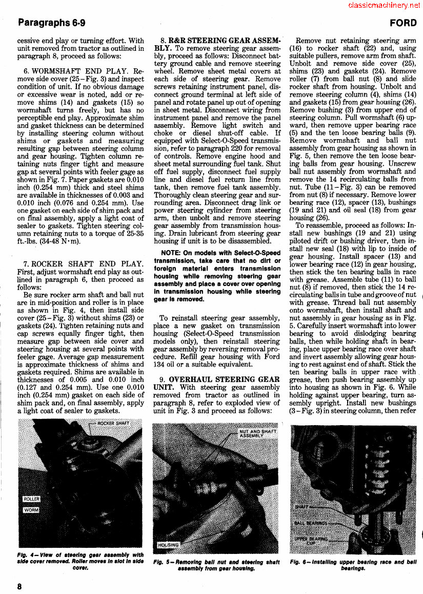
Paragraphs 6·9 cessive end play or turning effort. With unit removed from tractor as outlined in paragraph 8, proceed as follows: 6. WORMSHAFT END PLAY. Re- move side cover (25-Fig. 3) and inspect condition of unit. If no obvious damage or excessive wear is noted, add or re- move shims (14) and gaskets (15) so wormshaft turns freely, but has no perceptible end play. Approximate shim and gasket thickness can be determined by installing steering column without shims or gaskets and measuring resulting gap between steering column and gear housing. Tighten column re- taining nuts finger tight and measure gap at several points with feeler gage as shown in Fig. 7. Paper gaskets are 0.010 inch (0.254 mm) thick and steel shims are available in thicknesses of 0.003 and 0.010 inch (0.076 and 0.254 mm). Use one gasket on each side of shim pack and on final assembly, apply a light coat of sealer to gaskets. Tighten steering col- umn retaining nuts to a torque of 25-35 ftAbs. (34-48 N· m). 7. ROCKER SHAFT END PLAY. First, adjust wormshaft end playas out- lined in paragraph 6, then proceed as follows: Be sure rocker arm shaft and ball nut are in mid-position and roller is in place as shown in Fig. 4, then install side cover (25-Fig. 3) without shims (23) or gaskets (24). Tighten retaining nuts and cap screws equally finger tight, then measure gap between side cover and steering housing at several points with feeler gage. Average gap measurement is approximate thickness of shims and gaskets required. Shims are available in thicknesses of 0.005 and 0.010 inch (0.127 and 0.254 mm). Use one 0.010 inch (0.254 mm) gasket on each side of shim pack and, on final assembly, apply a light coat of sealer to gaskets. Fig. 4 - View of stee,'ng gea, assembly with 8. R&R STEERING GEAR ASSEM- BLY. To remove steering gear assem- bly, proceed as follows: Disconnect bat- tery ground cable and remove steering wheel. Remove sheet metal covers at each side of steering gear. Remove screws retaining instrument panel, dis- connect ground terminal at left side of panel and rotate panel up out of opening in sheet metal. Disconnect wiring from instrument panel and remove the panel assembly. Remove light switch and choke or diesel shut-off cable. If equipped with Select-O-Speed transmis- sion, refer to paragraph 220 for removal of controls. Remove engine hood and sheet metal surrounding fuel tank. Shut off fuel supply, disconnect fuel supply line and diesel fuel return line from tank, then remove fuel tank assembly. Thoroughly clean steering gear and sur- rounding area. Disconnect drag link or power steering cylinder from steering arm, then unbolt and remove steering gear assembly from transmission hous- ing. Drain lubricant from steering gear housing if unit is to be disassembled. NOTE: On models with Select·O·Speed transmission, take care that no dirt or foreign material enters transmission housing while removing steering gear assembly and place a cover over opening in transmission housing while steering gear Is removed. To reinstall steering gear assembly, place a new gasket on transmission housing (Select-O-Speed transmission models only), then reinstall steering gear assembly by reversing removal pro- cedure. Refill gear housing with Ford 134 oil or a suitable equivalent. 9. OVERHAUL STEERING GEAR UNIT. With steering gear assembly removed from tractor as outlined in paragraph 8, refer to exploded view of unit in Fig. 3 and proceed as follows: FORD Remove nut retaining steering arm (16) to rocker shaft (22) and, using suitable pullers, remove arm from shaft. Unbolt and remove side cover (25), shims (23) and gaskets (24). Remove roller (7) from ball nut (8) and slide rocker shaft from housing. Unbolt and remove steering column (4), shims (14) and gaskets (15) from gear housing (26). Remove bushing (3) from upper end of steering column. Pull wormshaft (6) up- ward, then remove upper bearing race (5) and the ten loose bearing balls (9). Remove wormshaft and ball nut assembly from gear housing as shown in Fig. 5, then remove the ten loose bear- ing balls from gear housing. Unscrew ball nut assembly from wormshaft and remove the 14 recirculating balls from nut. Tube (II-Fig. 3) can be removed from nut (8) if necessary. Remove lower bearing race (12), spacer (13), bushings (19 and 21) and oil seal (18) from gear housing (26). To reassemble, proceed as follows: In- stall new bushings (19 and 21) using piloted drift or bushing driver, then in- stall new seal (18) with lip to inside of gear housing. Install spacer (13) and lower bearing race (12) in gear housing, then stick the ten bearing balls in race with grease. Assemble tube (11) to ball nut (8) if removed, then stick the 14 re- circulating balls in tube and groove of nut ~ with grease. Thread ball nut assembly ~ onto wormshaft, then install shaft and nut assembly in gear housing as in Fig. 5. Carefully insert wormshaft into lower bearing to avoid dislodging bearing balls, then while holding shaft in bear- ing, place upper bearing race over shaft and invert assembly allowing gear hous- ing to rest against end of shaft. Stick the ten bearing balls in upper race with, grease, then push bearing assembly up into housing as shown in Fig. 6. While holding against upper bearing, tum as- sembly upright. Install new bushings (3 - Fig. 3) in steering column, then refer side core, removed. Rolle, moves In slot In side Fig. 5 - Removing ball nut and s, .. rlng shaft Fig. 6 -Installing uppe, bea,'ng ,ace and ball core,. assembly from gea, housing. bea,'ngs. 8
SHOP MANUAL to paragraph 6 for wormshaft adjust- ment and column installation. Insert rocker shaft and place dust seal (17) on outer end of shaft. Install steering arm (16) and tighten retaining nut to a tor- que of 150-190 ft.-lbs. (204-258 Nom). Place roller on end of ball nut (Fig. 4) and install side cover with proper shims and gaskets from rocker shaft adjust- ment as outlined in paragraph 7. Late Power Steering Models 5100· 7100·5600·5610·6600· 6610·7600·7610 10. These later power steering models use the integral power assist unit shown schematically in Fig. 8 and exploded in Fig. 9. A piston is built into shaft ball nut and a cylinder machined into gear- case housing; and entire case unit is pressurized by steering oil. Control is by means of a rotary valve which is built in- to piston and ball nut unit (12) and is not available separately. Pressure passage to top of piston (P) is internal while lower end is pressurized by external flow through pressure tube (24). Manual operation of steering gear is made possi- ble by a check ball (7) located in valve housing which recirculates oil within gear housing when pump is inoperative. 11. REMOVE AND REINSTALL. To remove steering gear assembly, first disconnect battery ground cable and remove steering wheel. Remove sheet metal covers at each side of steering gear. Remove screws retaining instru- ment panel, disconnect ground terminal Oeft side) and rotate panel up and out of opening in cowl. Disconnect wiring and remove instrument panel. Remove light switch and choke (or diesel shut-off cable). On Select-O-Speed models, refer to paragraph 220 for removal of con- trols. Remove engine hood and cowl. Shut off fuel, disconnect and remove fuel tank. Clean steering gear unit. Fig. 7- Measuring clearance between ge.r housing and steering column housing to deter· mIne shim and gasket thicknesses needed. Shim and gasket thickness requIred between gear housing and side cover Is determined In similar manner. Fig. 8 - Schematic view of I.te powe, steering gear unit used on some 5100 models and all others except 5200, eeooc, 76G0C, 8700, 8710, 7700 .nd 771a Steering c,lInde, Is built on ball nut and gear unit Is pressurized. Re'er to Fig. 9 for exploded view. Disconnect drag link and pump pressure and return lines, then unbolt and lift off steering gear assembly. NOTE: On Select·O·Speed models, make sure no dirt or foreign material falls into transmission during removal or while steering gear Is off. To install steering gear, reverse removal procedure. Torque four housing Fig. 9-Exploded view of I.'e powe, assls' s'eerlng gear. 1. Steering column 2. Steering shaft 3. Housing seal 4. Bushing sleeve 5. Shim pack 6. Valve housing 7. Check valve 8. Shim pack Paragraphs 11·12 base bolts to 135-165 ft.-Ibs. (184-224 Nom). Use a new transmission housing gasket on Select-O-Speed models. RefIll steering gear after complete assembly by cycling power steering, engine run- ning, while keeping pump reservoir filled. 12. OVERHAUL. Before disassem- bling the removed steering gear, tem- porarily reinstall steering wheel and disconnect external oil feed pipe (24-Fig. 9). Turn steering wheel from lock to lock several times until as much fluid as possible is pumped from hous- ing. Remove steering arm (15) using Special Tool 1001 or other suitable puller. Remove side cover (23), gasket (20), and rocker shaft end float shim (22). Turn steering shaft until rocker shaft arm is centered in housing opening as shown in Fig. 10, then withdraw rocker shaft. Remove the four stud nuts securing steering column (1- Fig. 9) and lift off column and shaft (2). Remove and save shim pack (5). Install oil seal protector sleeve (Tool SW 23/1 or FT.3147) over steering shaft spline as shown in Fig. 11, gently tap valve housing (6) away from 1 3 9. Bearing housing 10. Bearing 11. Piston ring 12. BaH nut 13. Guide peg 14. Dust seal 15. Steering ann 16. Oil seal 4"1 ~~ ~ fJ 231!~~. 17. Gear housing 18. Wear pin 19. Rocker shaft 20. Gasket 21. Spring 22. Float shim 23. Side cover 24. Pressure tube P. Piston 22 21 I 20 19 18 11 9
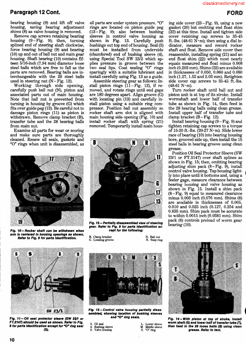
Paragraph 12 Cont. bearing housing (9) and lift off valve housing, saving bearing adjustment shims (8) as valve housing is removed. Remove cap screws retaining bearing housing (9 - Fig. 9); then, turning splined end of steering shaft clockwise, force bearing housing (9) and bearing (10) up and out of ball nut and main gear housing. Shaft bearing (10) contains fIf- teen 5/16-inch (7.94 mm) diameter loose steel balls which are free to fall as the parts are removed. Bearing balls are in- terchangeable with the 28 steel balls used in steering nut (N - Fig. 12). Working through side opening, carefully push ball nut (N), piston and associated parts out of main housing. Note that ball nut is prevented from turning in housing by groove (G) which fits over guide peg (13). Be careful not to damage piston rings (11) as piston is withdrawn. Remove clamp bracket (B), transfer tube and the 28 bearing balls from main nut. Examine all parts for wear or scoring and make sure parts are thoroughly cleaned. Renew all seals, gaskets and "0" rings when unit is disassembled, as FIg. 10-Rocker shaft can be wIthdrawn when arm Is centered In housIng openIngs as shown. Refer to FIg. S lor parts Identification. Fig. 11- 011 seal protector slee"e (SW 2:t'J or FT.3147) should be used as shown. Reier to FIg. S for parts Identification except lor "0" rIng seal (S). 10 all parts are under system pressure. "0" rings are located on piston guide peg (13 - Fig. 9); also between bushing sleeves in control valve housing as shown in Fig. 13. Carefully push bushings out top end of housing. Seal (3) must be installed from underside (chamfered) end of bushing sleeve (4), using Special Tool SW 23/2 which ap- plies pressure in groove between the two seal lips. Coat sealing "0" rings sparingly with a suitable lubricant and install carefully using Fig. 13 as a guide. Assemble steering gear as follows: In- stall piston rings (11- Fig. 12), if re- moved, and rotate rings until end gaps are 180 degrees apart. Align groove (G) with locating pin (13) and carefully in- stall piston using a suitable ring com- pressor. Position ball nut assembly so rocker shaft arm slot is aligned with main housing side opening (Fig. 10) and install rocker shaft with spring (21) removed. Temporarily install main hous- F'g. 12 - Partlall, d'sassembled "'ew of steerIng gear. Reier to FIg. S for parts Identification ex· cept lor the lollowlng: B. Clamp bracket G. Locating groove N. Ball nut R. Snap ring FIg. 13-Control "a/". housIng part/all, dlsas" sembled, . showIng locatIon of bushIng slee"es and ·0" ring se.'s. 3. Oil seal 4. Bushing sleeve 6. Valve housing L. Lower sleeve M. Middle sleeve S. "0" ring FORD ing side cover (23-Fig. 9), using a new gasket (20) but omitting end float shim (22) at this time. Install and tighten side t cover retaining cap screws to 35-45 ft.-lbs. (48-61 Nom); then using a dial in- dicator, measure and record rocker shaft end float. Remove side cover then reassemble, installing spring (21) and an end float shim (22) which most nearly equals measured end float minus 0.008 inch (0.203 mm). Shims (22) are available in thicknesses of 0.050, 0.060 and 0.080 inch (1.27,1.52 and 2.03 mm). Retighten side cover cap screws to 35-45 ft.-lbs. (48-61 Nom). Turn rocker shaft until ball nut and piston unit is at top of its stroke. Install wormshaft and lower half of transfer tube as shown in Fig. 14, then feed in the 28 bearing balls using clean grease. Install upper half of transfer tube and clamp bracket (B-Fig. 12). Install bearing housing (9 - Fig. 9) and tighten retaining cap screws to a torque of 15-20 ft.-Ibs. (20-27 Nom). Slide lower race of bearing (10) into bearing housing bore, grooved side up, then install the 15 steel balls in bearing groove using clean grease. Position Oil Seal Protector Sleeve (SW 23/1 or FT.3147) over shaft splines as shown in Fig. 15; then, omitting bearing adjusting shim pack (8-Fig. 9), install control valve housing. Tap housing light- • ly into place until it bottoms and, using a • feeler gage, measure clearance between bearing housing and valve housing as shown in Fig. 15. Install a shim pack (8-Fig. 9) equal to measured clearance minus 0.003 inch (0.076 mm). Shims (8) are available in thicknesses of 0.005, 0.010 and 0.025 inch (0.127, 0.254 and 0.635 mm). Shim pack must be accurate to within 0.0015 inch (0.0381 mm). Shim pack (8) controls preload of worm gear bearing (10). FIg. 14- With pIston at top of stroke, Insta" worm sh.ft (S) and lower hall 01 frans'er tube (T), then leed In the 28 loose balls (8) usIng clean grease. Refer to text.
The Ford 5610 Tractor OEM Service & Repair Manual is a comprehensive guide designed for professional technicians and do-it-yourself mechanics. It provides essential information for repairing and maintaining the Ford 5610 Tractor, making it a valuable resource for both professionals and enthusiasts.
This manual is tailored to individuals with basic knowledge of electrical and mechanical concepts. It covers a wide range of topics, including engine removal, wiring diagrams, lubrication points, periodic maintenance, fuel and lubrication systems, electrical systems, chassis, suspension, gearbox, cooling system, and more.
Key Product Details:
File Format: .PDF
Language: English
Specifications: Full Printable
Zoom IN/OUT: YES
Delivery: Instant
Requirements: Adobe Reader & Windows
Compatible: All Versions of Windows & Mac
Whether you opt for a paper manual or the digital version, you can expect the same features, including step-by-step repair procedures, critical specifications, illustrations, and detailed maintenance procedures. The digital version offers the convenience of instant access and can be downloaded straight to your computer.
The Ford 5610 Tractor OEM Service & Repair Manual is an invaluable resource that covers an extensive array of repair and maintenance procedures, supplying the knowledge needed to make informed decisions about maintaining and repairing the Ford 5610 Tractor.
Topics Covered:
Engine Removal
Wiring Diagrams
General Information
Lube Points
Oil Types
Periodic Maintenance and Tune-Up Procedures
Disassembly and Reassembly
Fuel and Lubrication Systems
Electrical System
Chassis, Steering, and Suspension
Service Data and Tools
Tightening Torques
Complete Engine Service
Factory Repair Procedures
Exhaust System
Cooling System
Maintenance Schedules
Electrics
Brake Servicing Procedures
Plus More
With its detailed and comprehensive content, the Ford 5610 Tractor OEM Service & Repair Manual is an essential resource for anyone involved in the maintenance and repair of the Ford 5610 Tractor.