Ford 3230/3430/3930/4630/4830 Tractors OEM Service & Repair Manual
What's Included?
Lifetime Access
Fast Download Speeds
Online & Offline Access
Access PDF Contents & Bookmarks
Full Search Facility
Print one or all pages of your manual
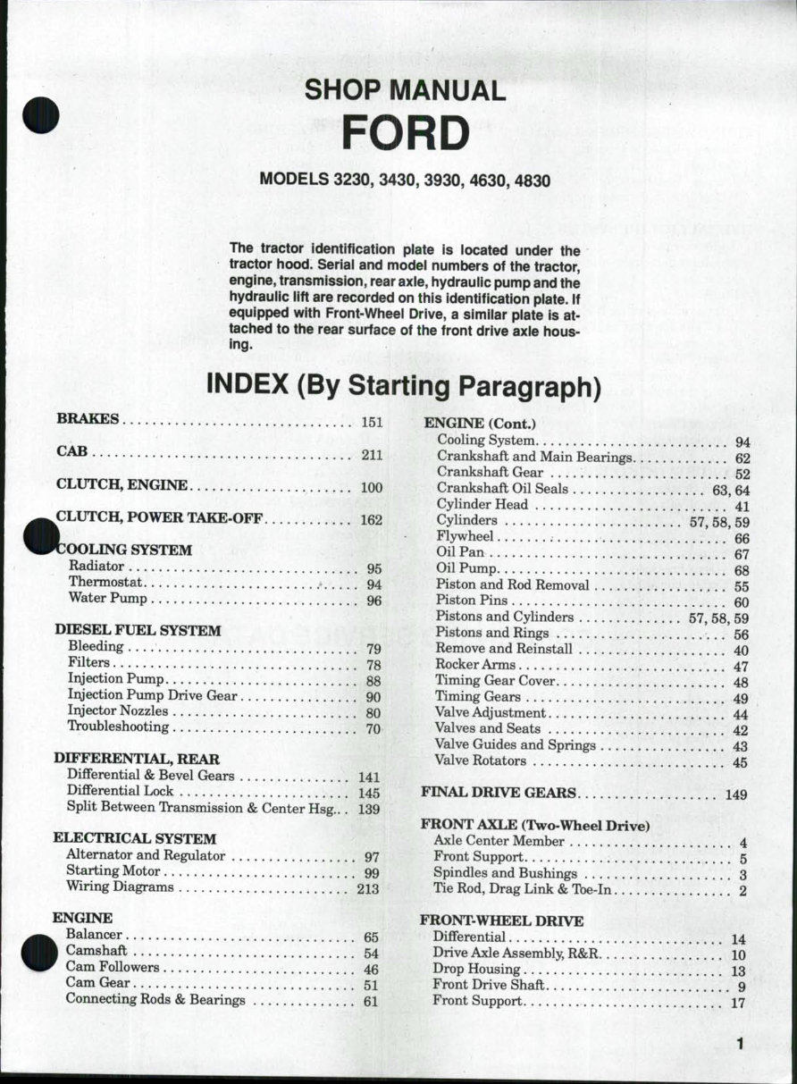
SHOP MANUAL FORD MODELS 3230, 3430, 3930, 4630, 4830 The tractor identification piate is located under tiie tractor hood. Seriai and modei numbers of the tractor, engine, transmission, rear axie, hydraulic pump and the hydrauiic iift are recorded on this identification piate. if equipped with Front-Wheei Drive, a similar piate is at- tached to the rear surface of the front drive axie hous- ing. INDEX (By Starting Paragraph) BRAKES CAB 151 211 m CLUTCH, ENGINE 100 CLUTCH, POWER TAKE-OFF 162 OOLING SYSTEM Radiator 95 Thermostat ^ 94 Water Pump 96 DDSSEL FUEL SYSTEM Bleeding 79 Filters 78 Injection Pump 88 Injection Pump Drive Gear 90 Injector Nozzles 80 Troubleshooting 70 DIFFERENTIAL, REAR DiflFerential & Bevel Gears 141 Differential Lock I45 Split Between Transmission & Center Hsg.. . 139 ELECTRICAL SYSTEM Alternator and Regulator 97 Starting Motor 99 Wiring Diagrams 213 ENGINE Balancer 65 Camshaft 54 Cam Followers 46 Cam Gear 51 Connecting Rods & Bearings 61 ENGINE (Cont.) Cooling System Crankshaft and Main Bearings. Crankshaft Gear Crankshaft Oil Seals Cylinder Head Cylinders Flywheel Oil Pan Oil Pump Rston and Rod Removal Piston Pins Pistons and Cylinders Pistons and Rings Remove and Reinstall Rocker Arms Timing Gear Cover Timing Gears Valve Adjustment Valves and Seats Valve Guides and Springs Valve Rotators 94 62 52 ... 63,64 41 57, 58, 59 66 67 ...... 68 ...... 55 60 57, 58, 59 56 40 47 48 49 44 42 43 45 FINAL DRIVE GEARS 149 FRONT AXLE (Two-Wheel Drive) Axle Center Member Front Support Spindles and Bushings Tie Rod, Drag Link & Ibe-In 4 5 3 2 FRONT-WHEEL DRIVE Differential Drive Axle Assembly, R&R. Drop Housing Front Drive Shaft Front Support 14 10 13 . 9 17
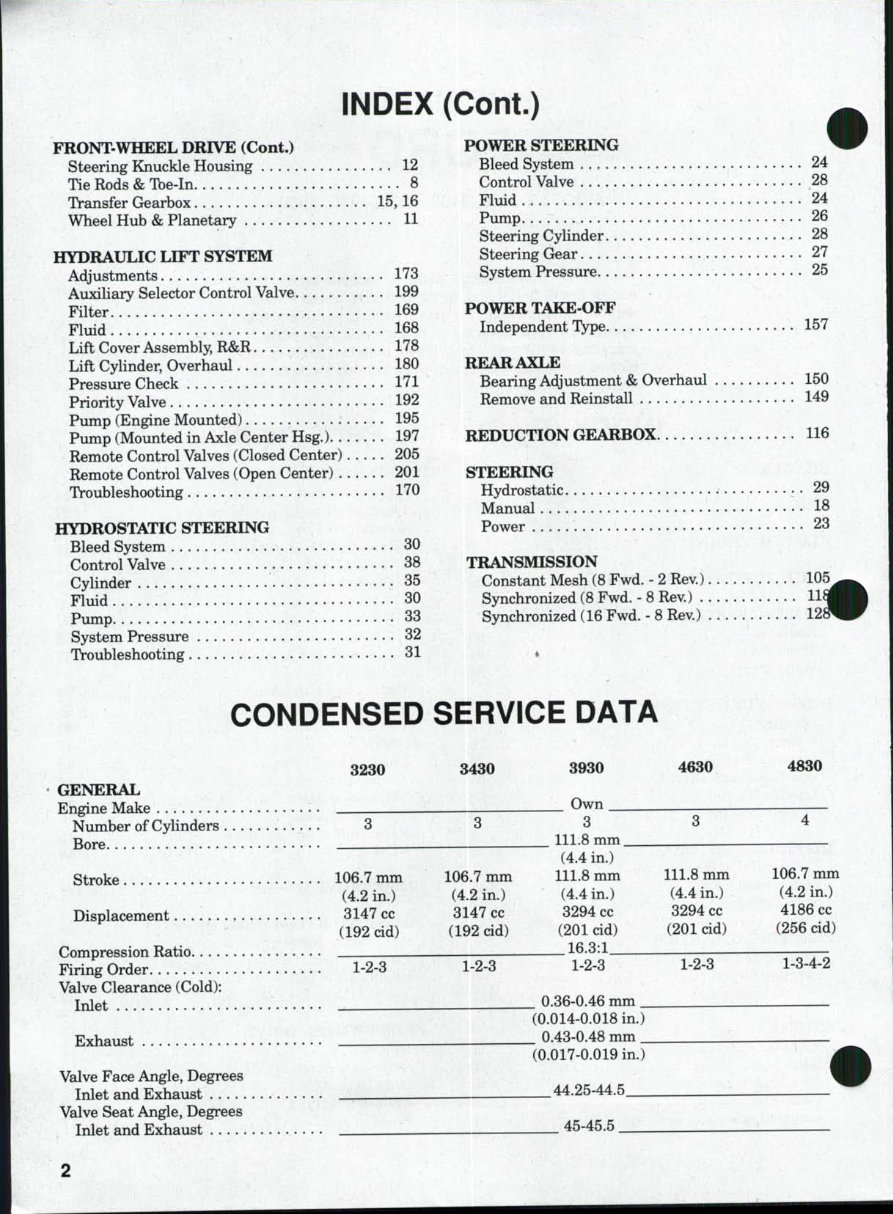
INDEX (Cont.) FRONT-WHEEL DRIVE (Cont.) Steering Knuckle Housing 12 Tie Rods & Ibe-In 8 Transfer Grearbox 15,16 Wheel Hub & Planetary 11 HYDRAULIC LIFT SYSTEM Adjustments 173 Auxiliary Selector Control Valve 199 Filter 169 Fluid 168 Lift Cover Assembly, R&R 178 Lift Cylinder, Overhaul 180 Pressure Check 171 Priority Valve 192 Pump (Engine Mounted) 195 Pump (Mounted in Axle Center Hsg.) 197 Remote Control Valves (Closed Center) 205 Remote Control Valves (Open Center) 201 Troubleshooting 170 HYDROSTATIC STEERING Bleed System 30 Control Valve 38 Cylinder 35 Fluid 30 Pump 33 System Pressure 32 TVoubleshooting 31 POWER STEERING Bleed System Control Valve Fluid Pump Steering Cylinder. . . Steering (jrear System Pressure..., 24 28 24 26 28 27 25 POWER TAKE-OFF Independent Type. . REAR AXLE Bearing Adjustment & Overhaul Remove and Reinstall 157 150 149 REDUCTION GEARBOX 116 STEERING Hydrostatic. Manual .... Power 29 18 23 TRANSMISSION Constant Mesh (8 Fwd. - 2 Rev.) Synchronized (8 Fwd. - 8 Rev.) . Synchronized (16 Fwd. - 8 Rev.) 105 Hi 12 CONDENSED SERVICE DATA 3230 GENERAL Engine Make Number of Cylinders 3 Bore Stroke 106.7 mm (4.2 in.) Displacement 3147 cc (192 cid) Compression Ratio Firing Order 1-2-3 Valve Clearance (Cold): Inlet Exhaust Valve Face Angle, Degrees Inlet and Exhaust Valve Seat Angle, Degrees Inlet and Exhaust 3430 106.7 mm (4.2 in.) 3147 cc (192 cid) 1-2-3 3930 Own 3 4630 4830 111.8 mm. (4.4 in.) 111.8 mm (4.4 in.) 3294 cc (201 cid) 1-2-3 _ 0.36-0.46 mm _ (0.014-0.018 in.) _ 0.43-0.48 mm _ (0.017-0.019 in.) 44.25-44.5 45-45.5 111.8 mm (4.4 in.) 3294 cc (201 cid) 1-2-3 106.7 mm (4.2 in.) 4186 cc (256 cid) 1-3-4-2
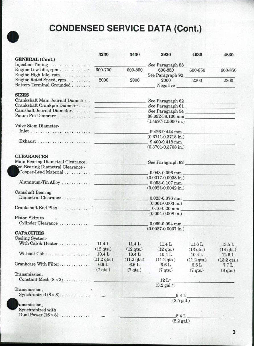
CONDENSED SERVICE DATA (Cont.) 3230 3430 3930 4630 4830 GENERAL (Cont.) Injection Timing See Paragraph 88 Engine Low Idle, rpm -. 600-700 600-850 600-850 600-850 600-850 Engine High Idle, rpm See Paragraph 92 Engine Rated Speed, rpm 2000 2000 2000 2200 2200 Battery Tferminal Grounded Negative SIZES Crankshaft Main Journal Diameter. . ___^__ See Paragraph 62 Crankshaft Crankpin Diameter See Paragraph 61 Camshaft Journal Diameter See Paragraph 54 Piston Pin Diameter 38.092-38.100 mm (1.4997-1.5000 in.) Valve Stem Diameter- Inlet ^ ^ 9.426-9.444 mm (0.3711-0.3718 in.) Exhaust 9.400-9.418 mm (0.3701-0.3708 in.) CLEARANCES Main Bearing Diametral Clearance. . ^ • ^ > d Bearing Diametral Clearance - ^^•Copper-Lead Material Aluminum-Tin Alloy Camshaft Bearing Diametral Clearance Crankshaft End Play ' Piston Skirt to Cylinder Clearance CAPACITIES Cooling System- With Cab & Heater 11.4 L (12 qts.) Without Cab 10.4 L (11.2 qts.) Crankcase With Filter 6.6 L (7 qts.) Transmission, Constant Mesh (8x2) Transmission, (8x8) f'ansmission, Synchronized with Dual Power (16 x 8) . See Paragraph 62 . _ 0.043-0.096 mm _ (0.0017-0.0038 in.) _ 0.053-0.107 mm _ (0.0021-0.0042 in.) 0.025-0.076 mm (0.001-0.003 in.) _ 0.10-0.20 mm _ (0.004-0.008 in.) _ 0.069-0.094 mm _ (0.0027-0.0037 in.) 11.4 L (12 qts.) 10.4 L (11.2 qts.) 6.6 L (7 qts.) 11.4 L (12 qts.) 10.4 L (11.2 qts.) 6.6 L (7 qts.) 11.6 L (13 qts.) 10.4 L (11.2 qts.) 6.6 L (7 qts.) 13.5 L (14 qts.) 12.5 L (13.2 qts.) 7.7 L (8 qts.) 12 L* "(3.2 gal. 9.4 L (2.5 gal.) _8.4L_ (2.2 gal.)
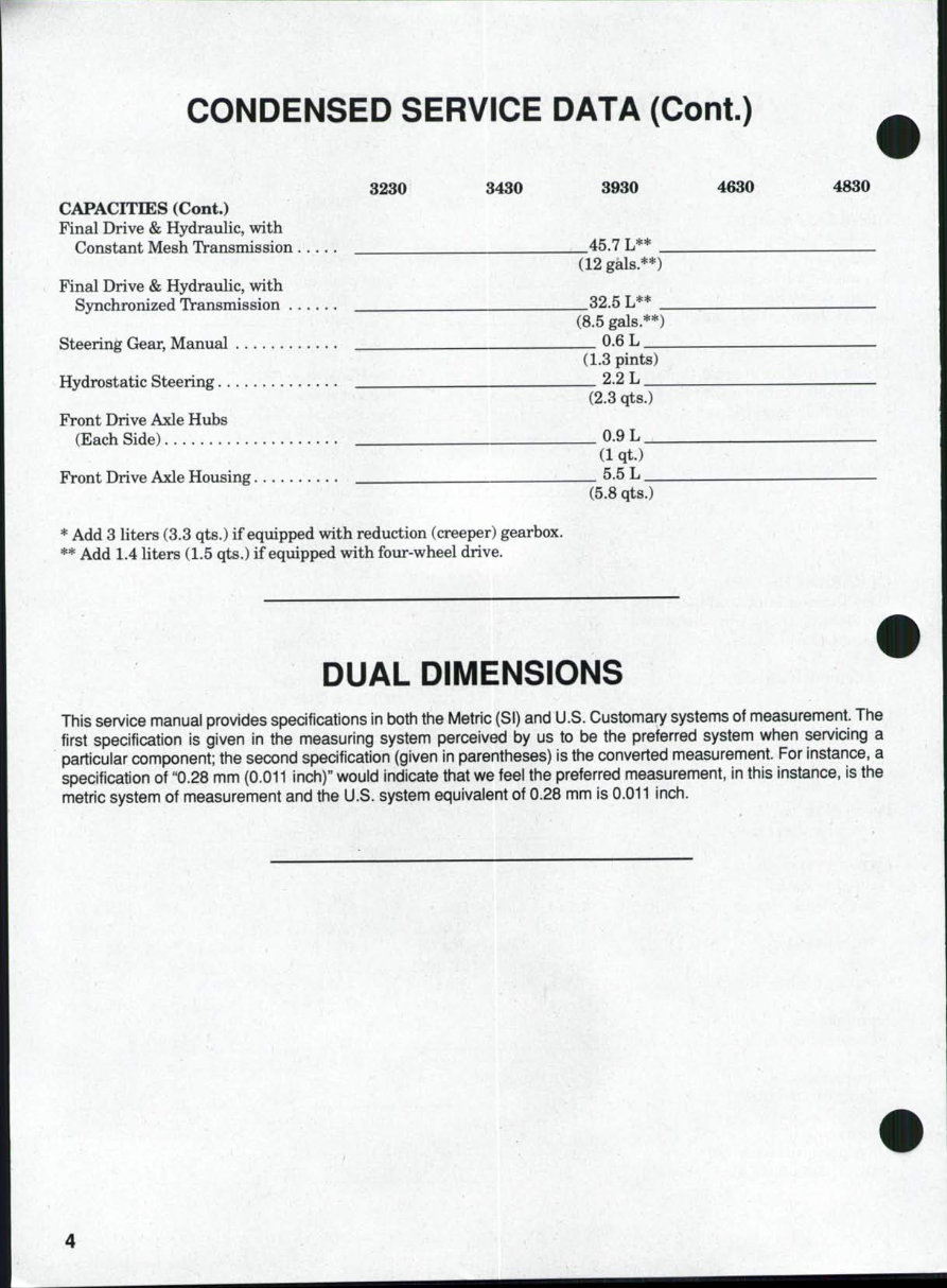
CONDENSED SERVICE DATA (Cont.) 3230 3430 3930 4630 4830 CAPACITIES (Cont.) Final Drive & Hydraulic, with Constant Mesh Transmission 45.7 L** (12 gals.**) Final Drive & Hydraulic, with S5nichronized Transmission ...... 32.5 L** . (8.5 gals.**) Steering Gear, Manual ..^ 0-6 L (1.3 pints) Hydrostatic Steering , 2.2 L _ (2.3 qts.) Front Drive Axle Hubs (Each Side) 0.9 L (1 qt.) Front Drive Axle Housing 5.5 L. (5.8 qts.) * Add 3 liters (3.3 qts.) if equipped with reduction (creeper) gearbox. ** Add 1.4 liters (1.5 qts.) if eqviipped with four-wheel drive. DUAL DIMENSIONS This service manual provides specifications in both the Metric (SI) and U.S. Customary systems of measurement. The first specification is given in the measuring system perceived by us to be the preferred system when servicing a particular component; the second specification (given in parentheses) is the converted measurement. For instance, a specification of "0.28 mm (0.011 inch)" would indicate that we feel the preferred measurement, in this instance, is the metric system of measurement and the U.S. system equivalent of 0.28 mm is 0.011 inch.
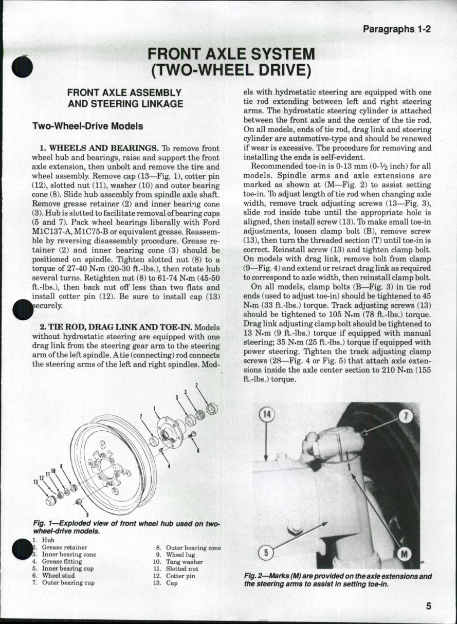
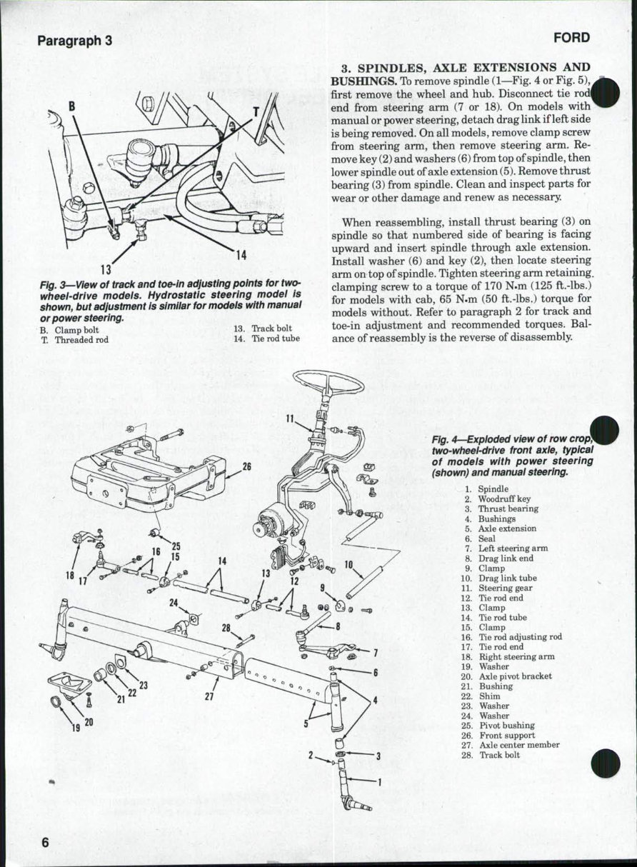
Paragraphs 1-2 FRONT AXLE SYSTEM (TWO-WHEEL DRIVE) FRONT AXLE ASSEMBLY AND STEERING LINKAGE Two-Wheel-Drive Models 1. WHEELS AND BEARINGS. Tb remove front wheel hub and bearings, raise and support the front axle extension, then unbolt and remove the tire and wheel assembly. Remove cap (13—Fig. 1), cotter pin (12), slotted nut (11), washer (10) and outer bearing cone (8). Slide hub assembly from spindle axle shaft. Remove grease retainer (2) and inner bearing cone (3). Hub is slotted to facilitate removal of bearing cups (5 and 7). Pack wheel bearings liberally with Ford M1C137-A, M1C75-B or equivalent grease. Reassem- ble by reversing disassembly procedure. Grease re- tainer (2) and inner bearing cone (3) should be positioned on spindle. Tighten slotted nut (8) to a torque of 27-40 N.m (20-30 ft.-lbs.), then rotate hub several turns. Retighten nut (8) to 61-74 N.m (45-50 ft.-lbs.), then back nut off less than two flats and install cotter pin (12). Be sure to install cap (13) lecurely. 2. TIE ROD, DRAG LINK AND TOE-IN. Models without hydrostatic steering are equipped with one drag link from the steering gear arm to the steering arm of the left spindle. Atie (connecting) rod connects the steering arms of the left and right spindles. Mod- Fig. 1—Exploded view of front wheei hub used on two- wheel-drlve models. Hub Grease retainer 8. Outer bearing cone Inner bearing cone 9. Wheel lug 4. Grease fitting 10. Tang washer 5. Inner bearing cup 11. Slotted nut 6. Wheel stud 12. Cotter pin 7. Outer bearing cup 13. Cap els with hydrostatic steering are equipped with one tie rod extending between left and right steering arms. The hydrostatic steering cylinder is attached between the front axle and the center of the tie rod. On all models, ends of tie rod, drag link and steering cylinder are automotive-type and should be renewed if wear is excessive. The procedure for removing and installing the ends is self-evident. Recommended toe-in is 0-13 mm (O-V2 inch) for all models. Spindle arms and axle extensions are marked as shown at (M—Fig. 2) to assist setting toe-in. Tb adjust length of tie rod when changing axle width, remove track adjusting screws (13—Fig. 3), slide rod inside tube until the appropriate hole is aligned, then install screw (13). Ib make small toe-in adjustments, loosen clamp bolt (B), remove screw (13), then tum the threaded section (T) until toe-in is correct. Reinstall screw (13) and tighten clamp bolt. On models with drag link, remove bolt from clamp (9—Fig. 4) and extend or retract drag link as required to correspond to axle width, then reinstall clamp bolt. On all models, clamp bolts (B—Fig. 3) in tie rod ends (used to adjust toe-in) should be tightened to 45 N.m (33 ft.-lbs.) torque. Track adjusting screws (13) should be tightened to 105 N.m (78 ft.-lbs.) torque. Drag link adjusting clamp bolt should be tightened to 13 N.m (9 ft.-lbs.) torque if equipped with manual steering; 35 N.m (25 ft.-lbs.) torque if equipped with power steering. Tighten the track adjusting clamp screws (28—Fig. 4 or Fig. 5) that attach axle exten- sions inside the axle center section to 210 N.m (155 ft.-lbs.) torque. Fig. 2—Marks (M) are provided on the axle extensions and the steering arms to assist in setting
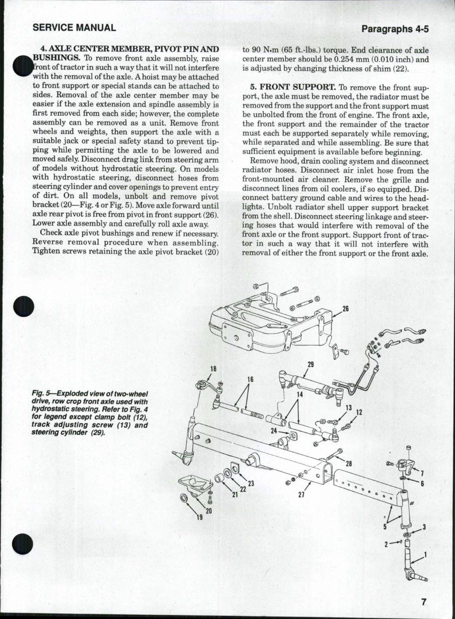
Paragraph 3 FORD B 14 Fig. 3—View of track and toe-in adjusting points for two- wheei-drive modeis. Hydrostatic steering model is shown, but adjustment is simiiar for modeis with manuai or power steering. B. Clamp bolt 13. Track bolt X Threaded rod 14. Tie rod tube 3. SPINDLES, AXLE EXTENSIONS AND BUSfflNGS. To remove spindle (1—Fig. 4 or Fig. 5), first remove the wheel and hub. Disconnect tie rod end from steering arm (7 or 18). On models with manual or power steering, detach drag link if left side is being removed. On all models, remove clamp screw from steering arm, then remove steering arm. Re- move key (2) and washers (6) from top of spindle, then lower spindle out of axle extension (5). Remove thrust bearing (3) from spindle. Clean and inspect parts for wear or other damage and renew as necessary. When reassembling, install thrust bearing (3) on spindle so that numbered side of bearing is facing upward and insert spindle through axle extension. Install washer (6) and key (2), then locate steering arm on top of spindle. Tighten steering arm retaining, clamping screw to a torque of 170 N.m (125 ft.-lbs.) for models with cab, 65 N.m (50 ft.-lbs.) torque for models without. Refer to paragraph 2 for track and toe-in adjustment and recommended torques. Bal- ance of reassembly is the reverse of disassembly. Fig. 4—Expioded view of row crop} two-wheei-drive front axie, typicai of modeis with power steering (shown) and manuai steering. 1. Spindle 2. WoodrufFkey 3. Thrust bearing 4. Bushings 5. Axle extension 6. Seal 7. Left steering arm 8. Drag link end 9. Clamp 10. Drag link tube 11. Steering gear 12. Tie rod end 13. Clamp 14. Tie rod tube 15. Clamp 16. Tie rod adjusting rod 17. Tie rod end 18. Right steering arm 19. Washer 20. Axle pivot bracket 21. Bushing 22. Shim 23. Washer 24. Washer 25. Pivot bushing 26. Front support 27. Axle center member 28. Track bolt
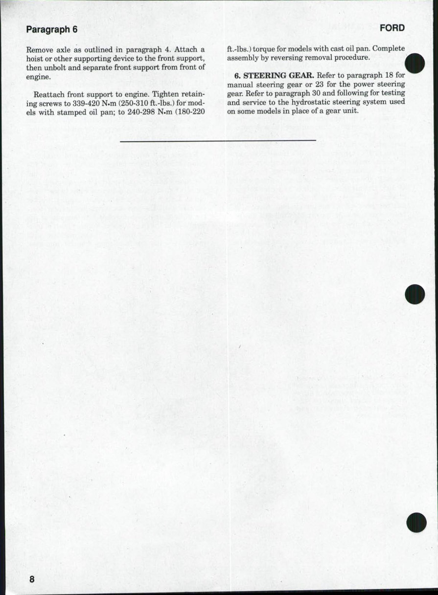
SERVICE MANUAL Paragraphs 4-5 4. AXLE CENTER MEMBER, PIVOT PIN AND ^BUSHINGS. Tb remove front axle assembly, raise ont of tractor in such a way that it will not interfere with the removal of the axle. A hoist may be attached to front support or special stands can be attached to sides. Removal of the axle center member may be easier if the axle extension and spindle assembly is first removed from each side; however, the complete assembly can be removed as a imit. Remove front wheels and weights, then support the axle with a suitable jack or special safety stand to prevent tip- ping while permitting the axle to be lowered and moved safely. Disconnect drag link from steering arm of models without hydrostatic steering. On models with hydrostatic steering, disconnect hoses from steering cylinder and cover openings to prevent entry of dirt. On all models, unbolt and remove pivot bracket (20—Fig. 4 or Fig. 5). Move axle forward until axle rear pivot is free from pivot in front support (26). Lower axle assembly and carefully roll axle away. Check axle pivot bushings and renew if necessary. Reverse removal procedure when assembling. Tighten screws retaining the axle pivot bracket (20) to 90 N.m (65 ft.-lbs.) torque. End clearance of axle center member should be 0.254 mm (0.010 inch) and is adjusted by changing thickness of shim (22). 5. FRONT SUPPORT. To remove the front sup- port, the axle must be removed, the radiator must be removed from the support and the front support must be unbolted from the front of engine. The front axle, the front support and the remainder of the tractor must each be supported separately while removing, while separated and while assembling. Be sure that sufficient equipment is available before beginning. Remove hood, drain cooling system and disconnect radiator hoses. Disconnect air inlet hose from the front-mounted air cleaner. Remove the grille and disconnect lines from oil coolers, if so equipped. Dis- connect battery ground cable and wires to the head- lights. Unbolt radiator shell upper support bracket from the shell. Disconnect steering linkage and steer- ing hoses that would interfere with removal of the front axle or the front support. Support front of trac- tor in such a way that it will not interfere with removal of either the front support or the front axle. Fig. 5—Exploded view of two-wheei drive, row crop front axie used with hydrostatic steering. Refer to Fig. 4 for iegend except damp boit (12), track adjusting screw (13) and steering cylinder (29).
Paragraph 6 Remove axle as outlined in paragraph 4. Attach a hoist or other supporting device to the front support, then unbolt and separate front support from front of engine. Reattach front support to engine. Tighten retain- ing screws to 339-420 N.m (250-310 ft.-lbs.) for mod- els with stamped oil pan; to 240-298 N.m (180-220 FORD ft.-lbs.) torque for models with cast oil pan. Complete assembly by reversing removal procedure. 6. STEERING GEAR. Refer to paragraph 18 for manual steering gear or 23 for the power steering gear. Refer to paragraph 30 and following for testing and service to the hydrostatic steering system used on some models in place of a gear imit. 8
SERVICE MANUAL Paragraphs 7-9 FRONT-WHEEL DRIVE 7. The mechanical front-wheel drive available on these models uses a front drive axle imit manufac- tured by Carraro. There are some differences be- tween the front-wheel drive systems used on these models, which will be referred to in the following servicing instructions. The transfer gearbox is engaged on some models by moving mechanical linkage shown in Fig. 18. On 4630 and 4830 models, engagement is controlled by an electric solenoid/hydrauhc valve that directs oil pres- sure to move the dog clutch (35—Fig. 20) and engage the front-wheel drive. The transfer gearbox is at- tached to the bottom of the rear axle center housing of all models. A drive shaft with two "U" joints con- nects the transfer gearbox to the front axle. TIE RODS AND TOE-IN All Models So Equipped 8. Tie rod ends may be one of several different types, but none are adjustable for wear; faulty units must be renewed. Tb check toe-in, first tum steering wheel so front heels are in straight-ahead position. Measure dis- t n c e at front and rear of front wheels from rim flange to rim fiange at hub height. Tbe-in should be 0-6 mm (O-V4 inch). Tb adjust toe-in of narrow tread models, loosen the lock nuts at each end of the tie rod, then turn the tie rod tube to set the toe-in. Tighten lock nuts at each end when adjustment is correct. Tb adjust toe-in of all other models (standard tread four-wheel drive), loosen clamp bolt (2—Fig. 6), then ^ B—View of toe-in adjustment points for four-wheel- drive models. Be sure to adjust both sides equally. 1. Adjuster 2. Clamp bolt 3. Tie rod end turn tie rod (1) in or out of tie rod end (3) as required. Adjust both sides evenly. When adjustment is correct, tighten clamp bolt (2) to 25 N.m (18 ft.-lbs.) torque. DRIVE SHAFT All Models So Equipped 9. REMOVE AND REINSTALL. Standard and waterproof drive shafts have been installed. Refer to Fig. 7 or Fig. 8 and the appropriate following para- graphs. To remove the standard drive shaft, first unbolt and remove the shield assembly (1—Fig. 7). Remove clamp bolts (3) from coupling, unbolt center bearing (9) from bracket, then slide couplings onto drive shaft and remove shaft. Grease couplings through fittings 10 11 Fig, 7—View of drive shaft and shield used on most four-wheei-drive modeis. Waterproof drive shaft is shown in Fig. 8. 1. 2. 3. 4. 5. 6. Shield Cover Clamp screw Nut Coupling Grease fitting 7. 8. 9. 10. 11. 12. Nut Screw Center bearing Center bracket Screw Drive shaft 9
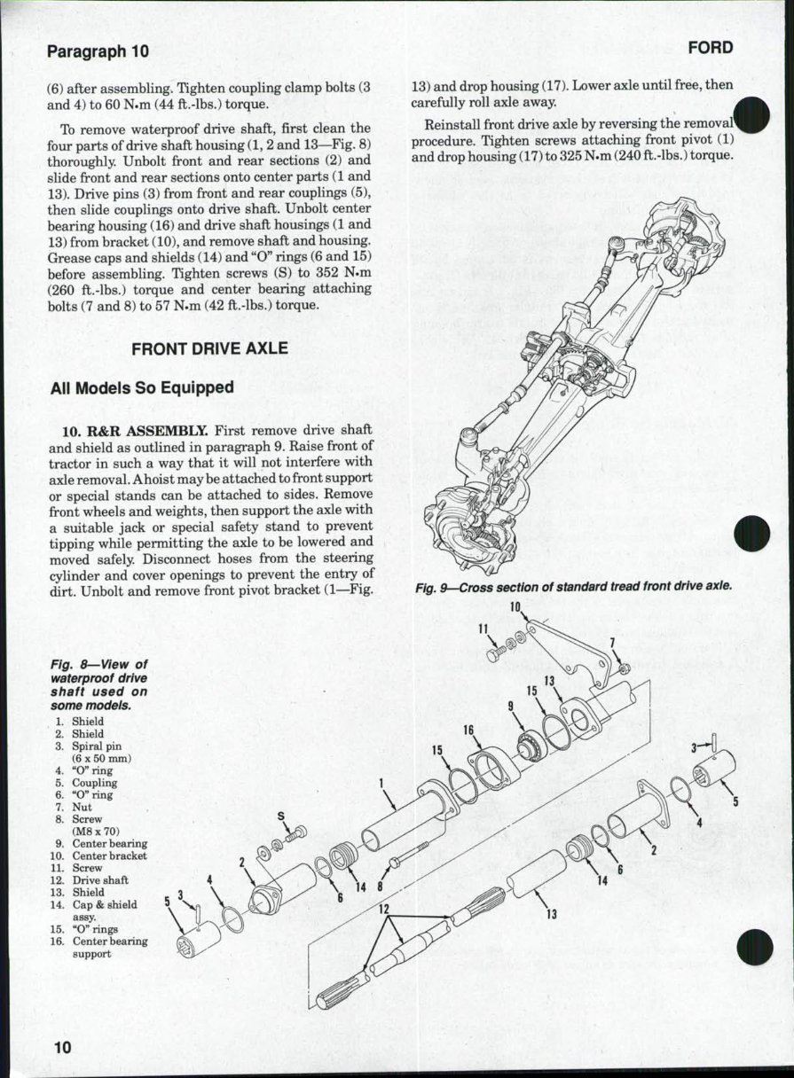
Paragraph 10 FORD (6) after assembling. Tighten coupling clamp bolts (3 and 4) to 60 N.m (44 ft.-lbs.) torque. Tb remove waterproof drive shaft, first clean the four parts of drive shaft housing (1, 2 and 13—Fig. 8) thoroughly. Unbolt front and rear sections (2) and slide front and rear sections onto center parts (1 and 13). Drive pins (3) from front and rear couplings (5), then slide couplings onto drive shaft. Unbolt center bearing housing (16) and drive shaft housings (1 and 13) from bracket (10), and remove shaft and housing. Grease caps and shields (14) and "O" rings (6 and 15) before assembling. Tighten screws (S) to 352 N.m (260 ft.-lbs.) torque and center bearing attaching bolts (7 and 8) to 57 N.m (42 ft.-lbs.) torque. FRONT DRIVE AXLE All Models So Equipped 10. R&R ASSEMBLY. First remove drive shaft and shield as outlined in paragraph 9. Raise front of tractor in such a way that it will not interfere with axle removal. Ahoist may be attached to front support or special stands can be attached to sides. Remove front wheels and weights, then support the axle with a suitable jack or special safety stand to prevent tipping while permitting the axle to be lowered and moved safely. Disconnect hoses from the steering cylinder and cover openings to prevent the entry of dirt. Unbolt and remove front pivot bracket (1—Fig. Fig. 8—View of waterproof drive shaft used on some models. 1. Shield 2. Shield 3. Spiral pin (6 X 50 mm) 4. "O" ring 5. Coupling 6. "Oaring 7. Nut 8. Screw (M8 X 70) 9. Center bearing 10. Center bracket 11. Screw 12. Drive shaft 13. Shield 14. Cap & shield assy. 15. "O" rings 16. Center bearing support 13) and drop housing (17). Lower axle until free, then carefully roll axle away. Reinstall front drive axle by reversing the removal' procedure. Tighten screws attaching front pivot (1) and drop housing (17) to 325 N.m (240 ft.-lbs.) torque. Fig. 9~-Cross section of standard tread front drive axie. 11 10
This OEM service and repair manual is designed exclusively for Ford Tractor models 3230, 3430, 3930, 4630, and 4830. Created for both professional mechanics and DIY enthusiasts, it provides easy-to-read text sections and high-quality diagrams along with step-by-step instructions and detailed exploded illustrations to guide you through every repair and maintenance task, ensuring your tractor remains in peak condition.
The manual covers a comprehensive array of topics, including:
Brakes
The CAB
Engine clutch
Power take-off clutch
Cooling system
Diesel-fuel system
Rear differential
Electrical system
Engine
Final drive
Front axle (two-wheel drive)
Front wheel drive
Hydraulic lift system
Hydraulic steering
Power steering
Power take-off
Rear axle
Reduction gearbox
Manual steering
Transmission
And more
This in-depth resource covers every detail of your machine, making it an essential guide for maintaining and repairing your Ford Tractor 3230, 3430, 3930, 4630, or 4830.
Accessible on both Windows and Mac platforms, this repair manual is a cost-effective tool to keep your vehicle functioning properly. Easily viewed with Adobe Reader or Win, it provides immediate access without any delay.
Recently Viewed
5,521,897Happy Clients
2,594,462eManuals
1,120,453Trusted Sellers
15Years in Business
Price:
Actual Price:
Ford 3230/3430/3930/4630/4830 Tractors OEM Service & Repair Manual