

Ford 2000, 3000, 4000, 5000, & 7000 Series Farm Tractor Service & Repair Manual
What's Included?
Fast Download Speeds
Online & Offline Access
Access PDF Contents & Bookmarks
Full Search Facility
Print one or all pages of your manual
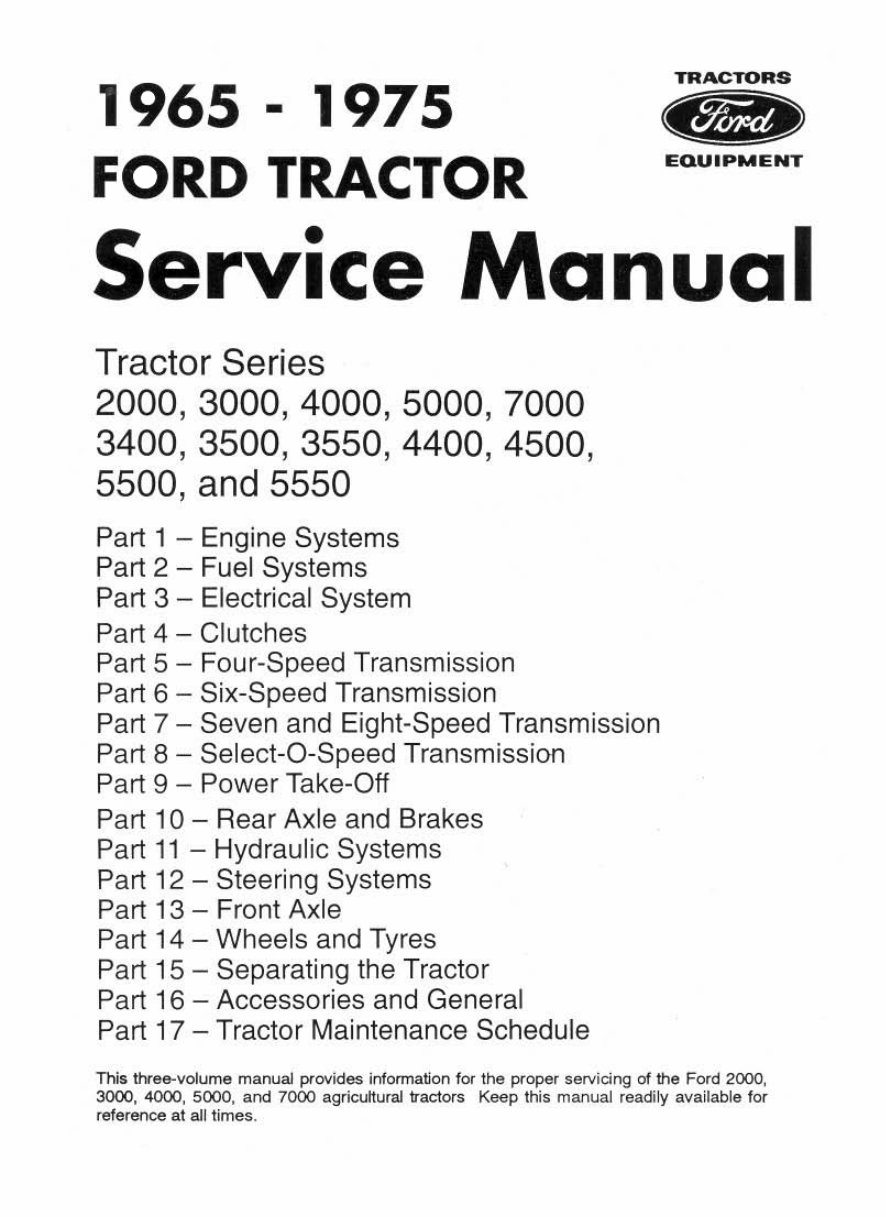
1965 - 1975
FORD TRACTOR
EQUIPMENT
Service Manual
Tractor Series
2000,3000,4000,5000,7000
3400,3500,3550,4400,4500,
5500, and 5550
Part 1 - En gine Systems
Part 2 - Fuel Systems
Part 3 - El ectrical System
Part 4 - Clutches
Part 5 - Four-Speed Transmission
Part 6 - Six-Speed Transmission
Part 7 - Seven and Eight-Speed Transmission
Part 8 - Select-a-Speed Transmission
Part 9 - Power Take-Off
Part 10 - Rear Axle and Brakes
Part 11 - Hydraulic Systems
Part 12 - Steering Systems
Part 13 - Front Axle
Part 14 - Wheels and Tyres
Part 15 - Separating the Tractor
Part 16 - Accessories and General
Part 17 - Tractor Maintenance Schedule
This three-volume manual p!"ovides informa~on for the p<oper servidng of the Ford 2000,
3000, 4000, 5000, and 7000 agricultural tractors Keep this manual readily available for
reference at all limes.
FOREWORD
This three-volume manual provides information for the proper servicing of the Ford 2000,
3000, 4000, 5000, and 7000 agricultural tractors Keep this manual readily available for
reference at all times.
The manual is grouped into 17 parts. Each part contains chapter divisions. The chapters
contain such information as general operating principles, detailed inspection and repair
procedures, and full specifics regarding troubleshooting, specifications, and special tools.
Whenever possible, the special tools are illustrated performing their specific operations.
The page and figure numbers are consecutively numbered throughout each part of the
manual and each page bears the date of issue. Specifications listed on some pages may differ
from those in the text. In these cases, the specifications listed on the pages bearing the latest
issue date should be used. Any reference made in the manual to right, left, front, rear, top, or
bottom, is as vi~wed facing the direction of forward travel from the driver's seat.
The tractor and engine serial numbers, and the production code numbers for the
transmission, hydraulic pump, rear axle and hydraulic power lift, are located on the individual
components. An explanation covering the usage and location of these numbers is detailed on
the following page. The serial numbers and production codes should be used on all
correspondence relative to these Ford tractors.
The material contained in this manual was correct at the time the manual was approved for
printing. Ford policy is one of continuous improvement and the Ford Motor Company reserves
the right to discontinue models at any time or change specifications or design without notice
and without incurring obligation.
A
SAFETY PRECAUTIONS
Appropriate seNice methods and proper repair procedures are essential for the safe, reliable
operation of all tractors, as well as the personal safety of the individual doing the work. This
manual provides general directions for accomplishing seNice and repair work with tested,
effective techniques. Following them will help ensure reliability.
There are numerous variations in procedures, techniques, tools, and parts for seNicing
tractors, as well as in the skill of the individual doing the work. This manual cannot possibly
anticipate all such variations and provide advice or cautions as to each. Accordingly, anyone
who departs from the instructions provided in this manual must first establish that he
compromises neither his personal safety nor the machine integrity by his choice of methods,
tools, or parts.
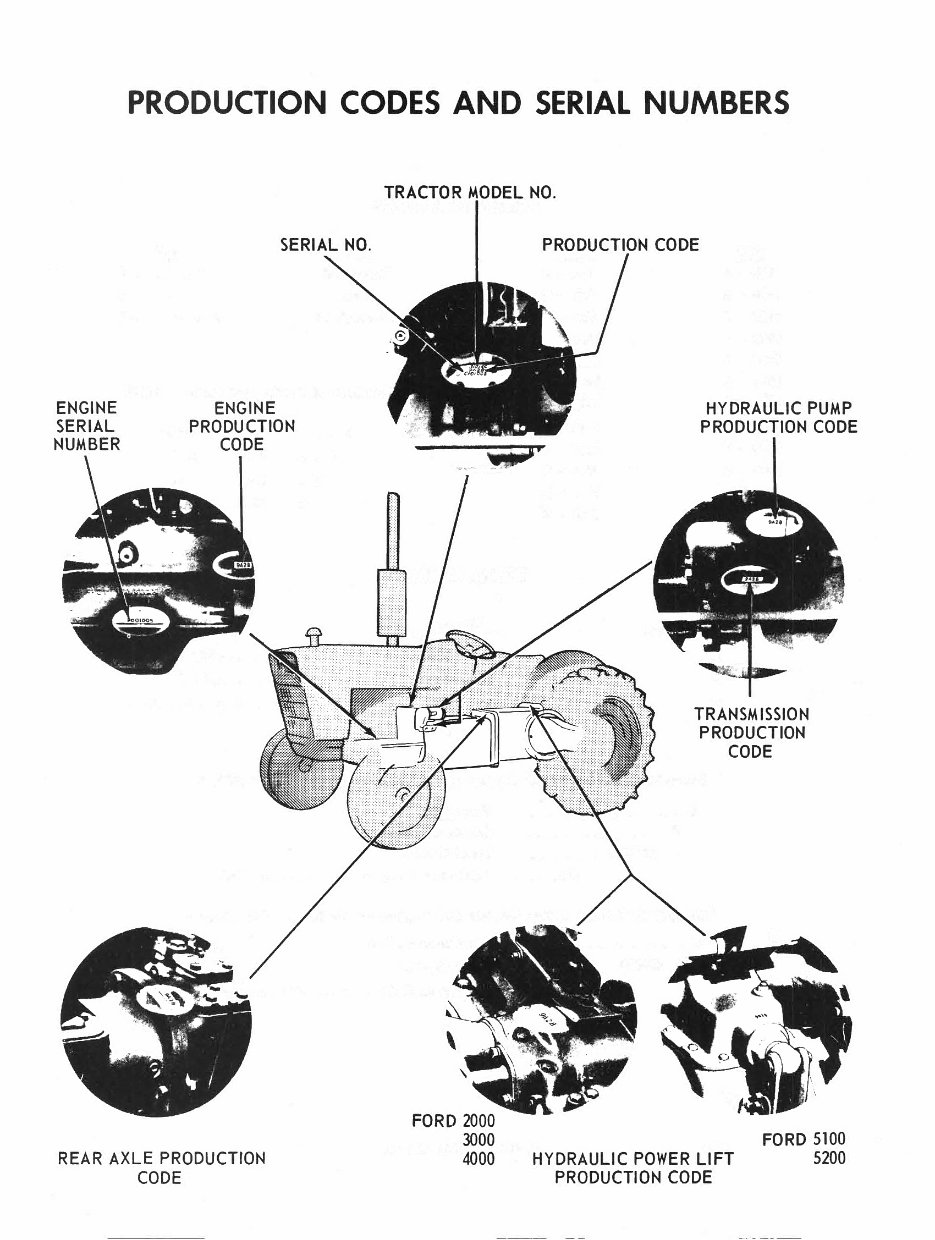
PRODUCTION CODES AND SERIAL NUMBERS
ENGINE
SERIAL
NUMBER
ENGINE
PRODUCTION
CODE
REAR AXLE PRODUCTION
CODE
TRACTOR NO.
,
FORD 2000
3000
4000
RODIUClr10N CODE
HYDRAULIC PUMP
PRODUCTION CODE
TRANSMISSION
PRODUCTION
CODE
FORD 5100
HYDRAULIC POWER LIFT 5200
PRODUCTION CODE
·'
{
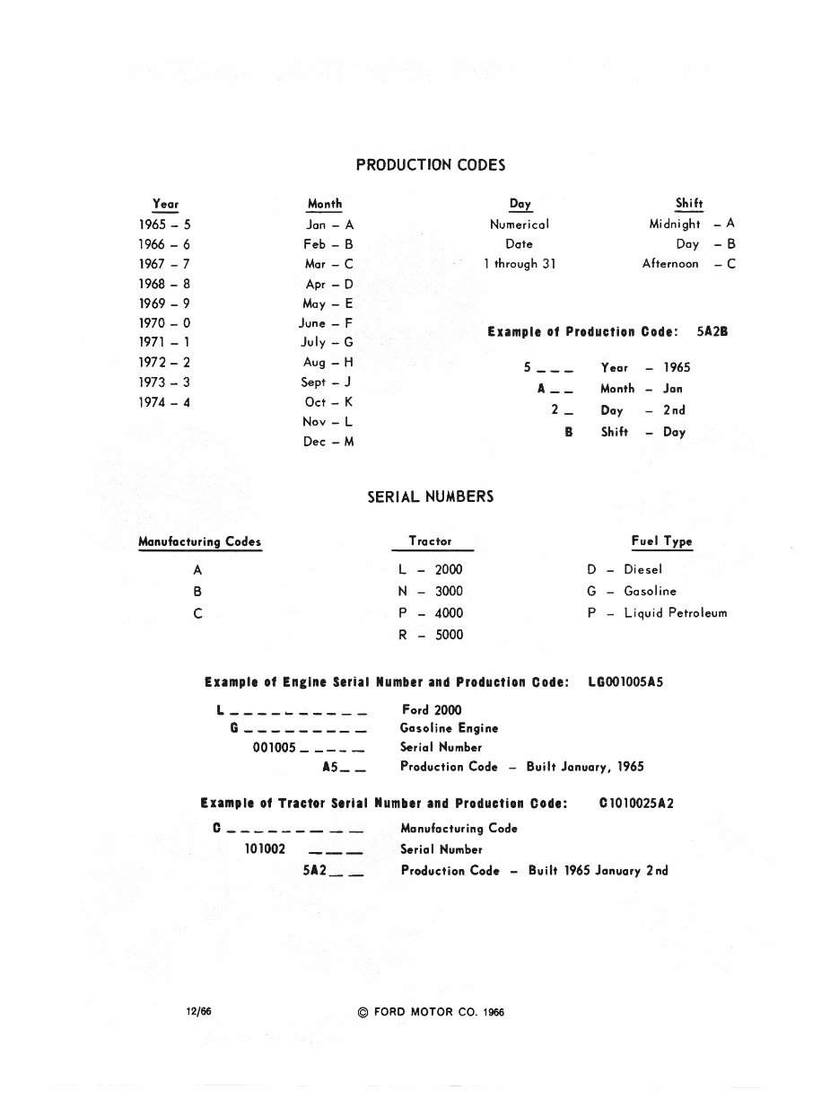
PRODUCTION CODES
Year Day Shift
1965 - 5 Numerical Midnight
_A
1966 - 6
Date Day -B
1967 - 7 1 through 31 Afternoon
-C
1968 - 8
1969 - 9
1970 - 0
Month
Jan - A
Feb - B
Mar - C
Apr -I;>
May - E
June , - F
July - G
Aug - H
Sept - J
Oct - K
Nov - L
Dec - M
Example of Production Code : 5A2B
1971 - 1
1972 - 2
5 ___
Year 1965
1973 - 3
A __
Month
-
Jan
1974 - 4
2_
Day
-
2nd
..
B Shift
-
Day
~':~~~;, ,
"
~.
,.~
""'~
"
",'i
1<":';"-
SERIAL NUMBERS
•
Manufacturing' Code. Fuel Type
Exampl. of Ellin. Serial Number and ' Production Code: LGool005A5
L _________ _
G ________ _
001005 ____ _
A5 __
Ford 2000
Gasoline Engine
Serial Humber
Production Code - Built January, 1965
EIIIII,I. of Tractor Serial Numhr and Producti.n Cod.: Cl0l0025A2
12/66
C _ _ _ _ _ _ _ _ _ Monufacturing Code
101002 ___ ', Serial Humber
512 __ ' Production Code - Built 1965 January 2nd
j ti, -"'\ " !
)1' ",<.100,
1.
" © FORD MOTOR CO, 1966

NEW MODELS
------------------------NEWMODELSUPp~EMENT------------------------
FORE'VORD
, '
This Supplem ent covers the m-ajor differences between new and previous type Ford 2000, 3000, 4000 snp SOOO
Agricultural tractors. The mechanical changes detailed also apply to Ford 3400, 3500, 4400, 4500 and 5500 Indus-
trial models. Changes to styling have little effect on service procedures, therefore where changes are merely ones
of appearance, reference to the Parts Catalog should be made when replacing such items as tadiator grilles, hoods
and exhaust mufflers .
SERIAL NUMBERING AND DATE CODING
The following Serial Numbering and Coding information should be noted:
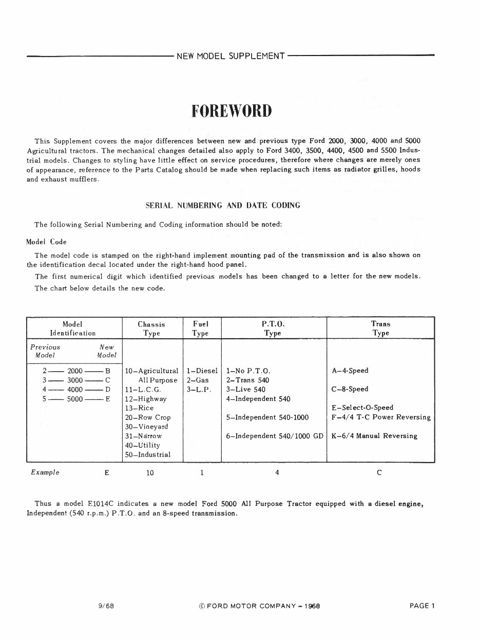
Model Code
The model code is stamped on the right-hand implement mounting pad of the transmission and is also shown on
the identification decal located under the right-hand hood panel.
The first numerical digit which identified previoils models has been changed to 8 letter for the new models.
The chart below de tails the new code.
,
Model Chassis Fuel P.T.O. Trans
Identification Type Type Type Type
Previous New
Model Model
2-- 2000--8 la-Agricultural l-Diesel I-No P.T.O. A-4-Speed
3-- 3000--C All Purpose 2-Gas 2- Trans 540
4-- 4000--D ll-L.C.G. 3-L.P. 3-Live 540 C-8-Speed
5-- 5000--E 12-Highway 4-lndependent 540
13-Rice E-Select-O-Speed
20-Row Crop 5-lndependent 540-1000 F-4/4 T-C Power Reversing
30- Vineyard
3l-Narrow 6-lndependent 540/1000 GD K-6/4 Manual Reversing
40-Utility
SO-Industrial
Example E 10 I 4 C
Thus a model El014C indicates a new model Ford 5000 All Purpose Tractor equipped with 8 diesel engine,
Independent (540 r.p.m.) P.T.O . and an 8-speed transmission .
9/68 © FORD MOTOR COMPANY - 1968 PAGE 1
------------------------NEWMODEL5UPPLEMENT------------------------
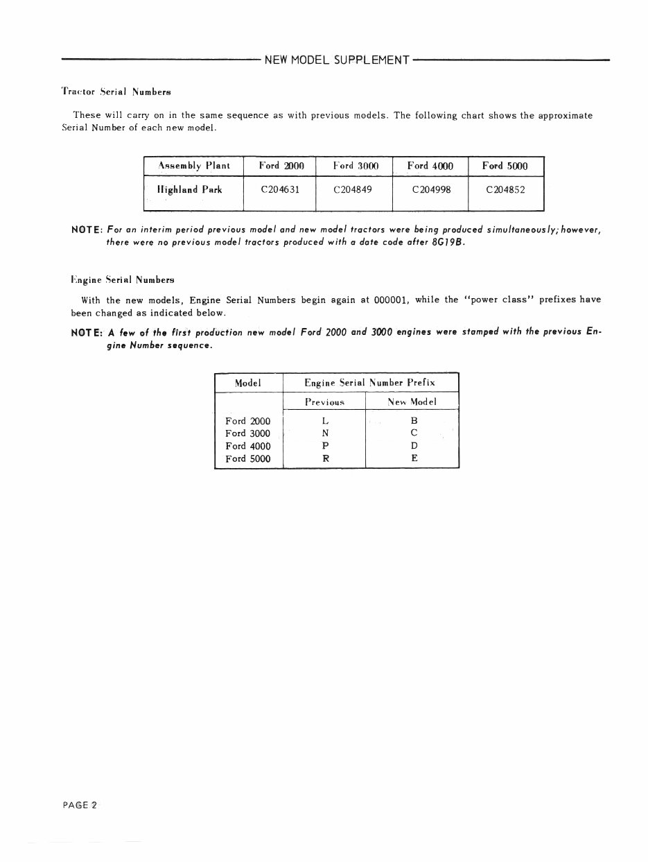
Tra(!tor Serial Numbers
These will carry on in the same sequence as with previous models. The following chart shows the approximate
Serial Number of each new model.
A""embly PI.nt Ford ~Of) Ford 3000 Ford 4000 Ford 5000
II ighland Park C204631 C204849 C204998 C204852
NOTE: For an interim perioJ previous model and new model tractors were being produced simultaneously; however,
there were no previous model tractors produced with a date code after BG19B.
Engine Serial Numbers
With the new models, Engine Serial Numbers begin again at 000001, while the Hpower class" prefixes have
been changed as indicated below.
NOT E: A few of tho lirst production new model Ford 2000 and 3000 "nginos were stamped with the pr~vious fn-
gine Number sequence.
Model Engine Serial Number Prefix
Previous New Model
Ford 2000 L B
Ford 3000 N C
Ford 4000 P D
Ford 5000 R E
PAGE 2
------------------------NEWMODELSUPPLEMENT------------------------
Part 1
.,
ENGINE SYSTEMS
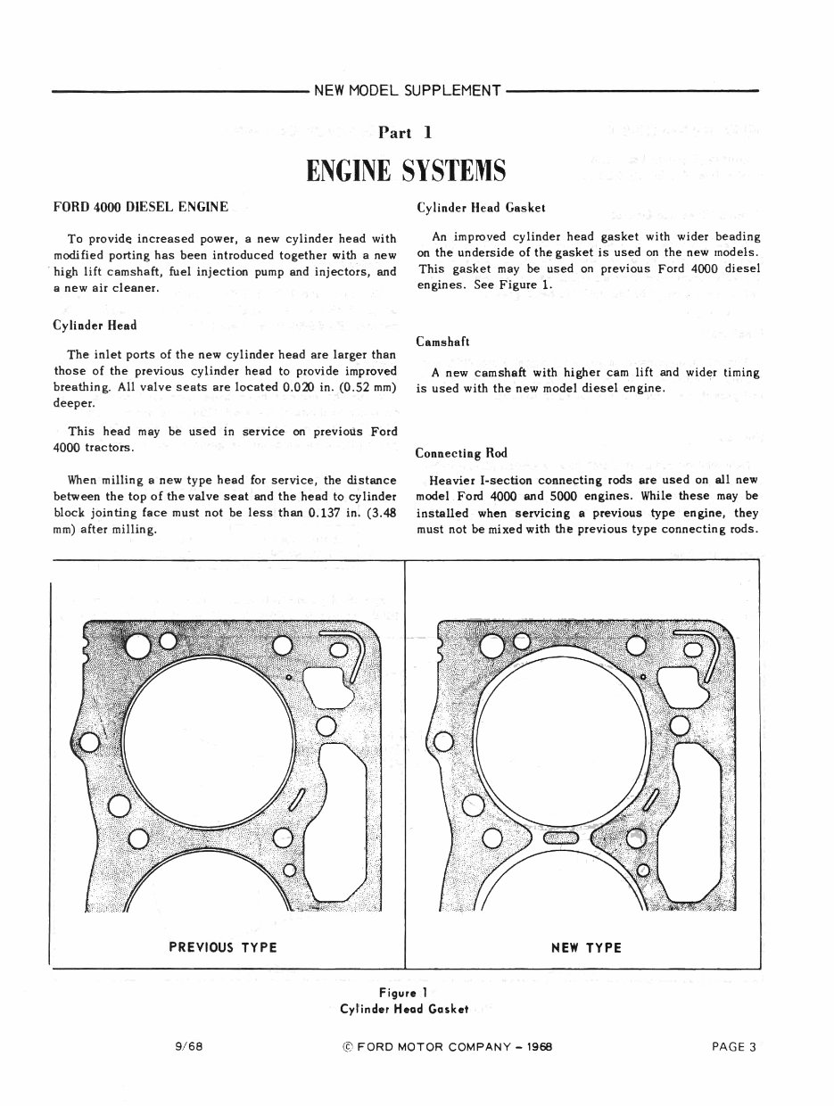
FORD 4000 DIESEL ENGINE
To provide increased power, a new cylinder head with
modified porting has been int roduced together with a new
. high lift camshaft, fuel injection pump and injectors , and
a new air cleaner.
Cylinder Head
The inlet ports of the new cylinder head are larger than
those of the previous cylinder head to provide improved
breathing. All valve seats are located 0.020 in. (0.52 mm)
deeper.
This head may be used in service on previous Ford
4000 tractors.
When milli ng 8 new type head for service , the distance
between the top of the valve seat and the head to cylinder
block jointing face must not be less than 0.137 in. (3.48
mm) aft er milling.
PREVIOUS TYPE
Cylinder Head Gasket
An improved cylinder head gasket with wider beading
on the underside of the gasket is used on the new models.
This gasket may be used on previous Ford 4000 diesel
engines. See Figure 1.
Camshaft
A new camshaft with higher cam lift and wider timing
is used with the new model diesel en'gine.
,
Connecling Rod
Heavier I·section connecting rods are used on all new
model Ford 4000 and 5000 engines. Whi1.e these may be
installed when servicing a previous type engine, they
must not be mixed with the previous type connecting rods .
0.
NEW TYPE
Figur. 1
Cylinder Head Gask.t
9/ 68 © FORD MOTOR COMPANY - 1968 PAGE 3
-----------------------NEWMODELSUPPLEMENT------______________ __
FonD 4000 GAS ENGINE
Increased power has been obtained by increasing the
stroke from 4.2 in. (106.68 mm) to. 4.4 in. (111.76 mm).
Cylinder lie ad and Gasket
A new cylinder head has been introduced which differs
from that used on previous Ford 4000 gas engines in that
the valve seats are located 0.020 in. (0.52 mm) deeper .
There is no change to the cylinder head gasket .
Crankshaft
The crankshaft used in the new model Ford 4000 gas
engine is common with the Fo;d 4000 diesel crankshaft
and provides a stroke of 4.4 in. (111.76 mm).
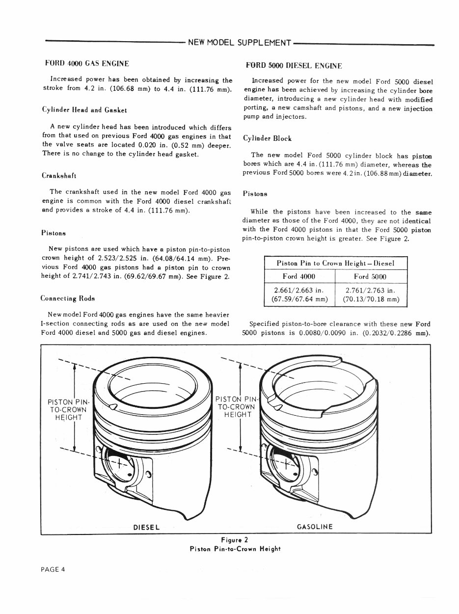
Pistons
New pistons are used which have a piston pin~to-piston
crown height of 2.523/ 2.525 in. (64.08/ 64.14 mm) . Pr ...
vious Ford 4000 gas pistons had 8 piston pin to crown
height of 2.741/ 2.743 in. (69.62/ 69.67 mm). See Figure 2.
Connecting Rods
New model Ford 4000 gas engines have the same heavier
[-section connecting rods as are used on the new model
Ford 4000 diesel and 5000 gas and diesel engines.
FORD 5000 DIESEL ENGINE
locreased power for the new model Ford 5000 diesel
engine has been achieved by incre as ing th e cylinder bore
diameter, introducing a new cylinder he ad with modified
porting. a new camshaft and pistons , and a new injection
pump and injectors.
Cylluder Block
The new model Ford 5000 cylinder block has piston
bores which are 4.4 in . (111.76 mm) diameter, whereas the
previous Ford 5000 bores were 4. 2in. (106.88mm) diameter.
PistoDS
While the pistons have been increased to the same
diameter as those of the Ford 4000, they are not identical
with the Ford 4000 pistons in that the Ford 5000 piston
pin-to-piston crown height is greater. See Figure 2.
PistOD Pin to Crown Height - Diesel
Ford 4000 Ford 5000
2.661/2 .663 in. 2.761/ 2.763 in .
(67.59/ 67.64 mm) (70.13/70.18 mm)
Specified piston-ta-bore clearan ce with these new Ford
5000 pistons is 0.0080/ 0.0090 in. (0.2032/ 0.2286 mm).
--r-
--r-
PISTON PIN·
TO·CROWN
HEIGHT
--1
--
PAGE 4
DIESE L
""
PISTON PIN·
TO-CROWN
HEIGHT
-J
---
Figur.2
Piston Pin-to-Crown Height
GASOLINE
You're Reading a Preview
What's Included?
Fast Download Speeds
Online & Offline Access
Access PDF Contents & Bookmarks
Full Search Facility
Print one or all pages of your manual
$27.99
Viewed 21 Times Today


Secure transaction
What's Included?
Fast Download Speeds
Online & Offline Access
Access PDF Contents & Bookmarks
Full Search Facility
Print one or all pages of your manual
$27.99
This manual provides service information for the Ford 2000, 3000, 4000, 5000, & 7000 Series Farm Tractors, as well as the Ford 3400, 3500, 3550, 4400, 4500, 5500, & 5550 Farm Tractors. With 913 pages, it is packed with schematics, photos, drawings, and written instructions to assist in the repair or restoration of your Ford tractor. It covers tasks ranging from simple to the most complex, making it a valuable resource for both professional mechanics and DIY enthusiasts.


