FOREWORD This supplement contains service and repair information not included in the 1000 Series Tractor Repair Manual, SE 3771.
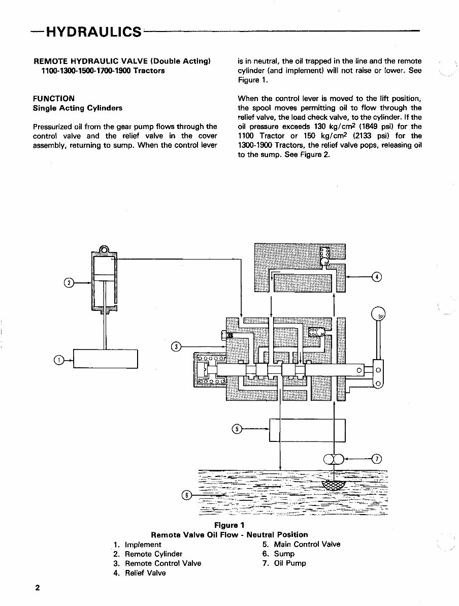
— HYDRAULICS REMOTE HYDRAULIC VALVE (Double Acting) 1100-1300-1500-1700-1900 Tractors FUNCTION Single Acting Cylinders Pressurized oil from the gear pump flows through the control valve and the relief valve in the cover assembly, returning to sump. When the control lever is in neutral, the oil trapped in the line and the remote cylinder (and implement) will not raise or lower. See Figure 1. When the control lever is moved to the lift position, the spool moves permitting oil to flow through the relief valve, the load check valve, to the cylinder. If the oil pressure exceeds 130 kg/cm2 (1849 psi) for the 1100 Tractor or 150 kg/cm2 (2133 psi) for the 1300-1900 Tractors, the relief valve pops, releasing oil to the sump. See Figure 2. Figure 1 Remote Valve Oil Flow - Neutral Position 1. Implement 5. Main Control Valve 2. Remote Cylinder 6. Sump 3. Remote Control Valve 7. Oil Pump 4. Relief Valve
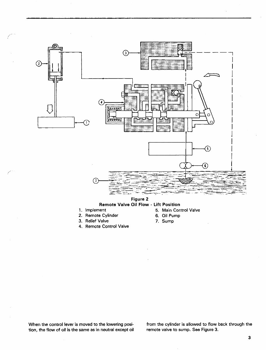
Figure 2 Remote Valve Oil Flow - Lift Position 1. Implement 5. Main Control Valve 2. Remote Cylinder 6. Oil Pump 3. Relief Valve 7. Sump 4. Remote Control Valve When the control lever is moved to the lowering posi- tion, the flow of oil is the same as in neutral except oil from the cylinder is allowed to flow back through the remote valve to sump. See Figure 3.
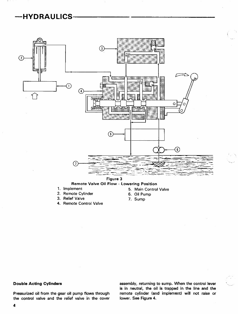
HYDRAULICS Figure 3 Remote Valve Oil Flow - Lowering Position 1. Implement 5. Main Control Valve 2. Remote Cylinder 6. Oil Pump 3. Relief Valve 7. Sump 4. Remote Control Valve Double Acting Cylinders Pressurized oil from the gear oil pump flows through the control valve and the relief valve in the cover assembly, returning to sump. When the control lever is in neutral, the oil is trapped in the line and the remote cylinder (and implement) will not raise or lower. See Figure 4.
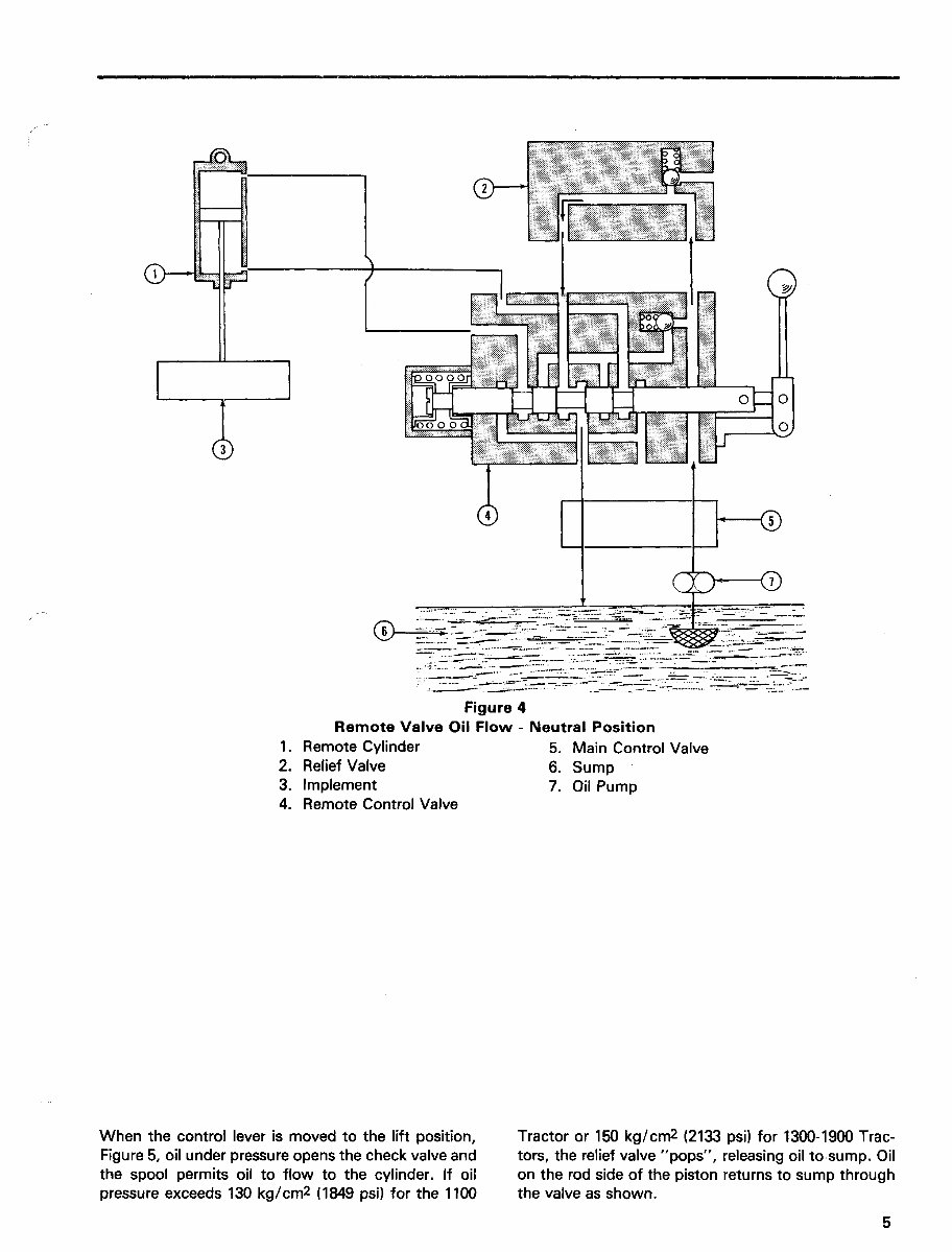
Figure 4 Remote Valve Oil Flow - Neutral Position 1. Remote Cylinder 5. Main Control Valve 2. Relief Valve 6. Sump 3. Implement 7. Oil Pump 4. Remote Control Valve When the control lever is moved to the lift position, Figure 5, oil under pressure opens the check valve and the spool permits oil to flow to the cylinder. If oil pressure exceeds 130 kg/cm2 (1849 psi) for the 1100 Tractor or 150 kg/cm2 (2133 psi) for 1300-1900 Trac- tors, the relief valve "pops", releasing oil to sump. Oil on the rod side of the piston returns to sump through the valve as shown.
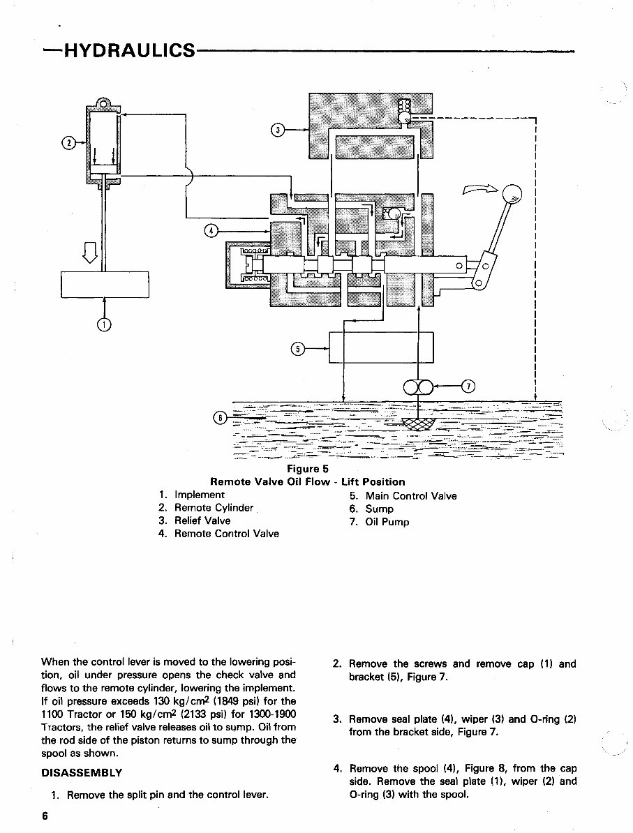
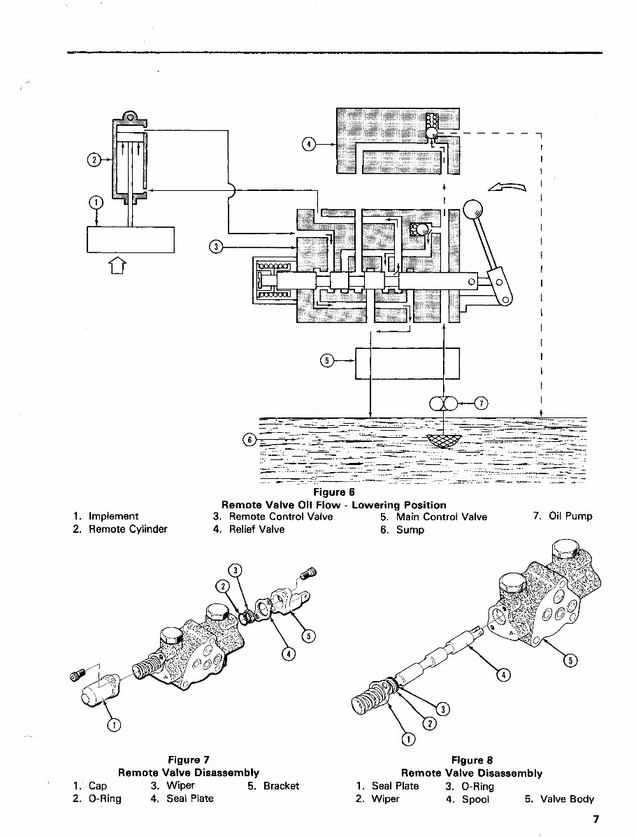
—HYDRAULICS Figure 5 Remote Valve Oil Flow - Lift Position 1. Implement 5. Main Control Valve 2. Remote Cylinder 6. Sump 3. Relief Valve 7. Oil Pump 4. Remote Control Valve When the control lever is moved to the lowering posi- tion, oil under pressure opens the check valve and flows to the remote cylinder, lowering the implement. If oil pressure exceeds 130 kg/cm2 (1849 psi) for the 1100 Tractor or 150 kg/cm2 (2133 psi) for 1300-1900 Tractors, the relief valve releases oil to sump. Oil from the rod side of the piston returns to sump through the spool as shown. DISASSEMBLY 1. Remove the split pin and the control lever. 2. Remove the screws and remove cap (1) and bracket (5), Figure 7. 3. Remove seal plate (4), wiper (3) and O-ring (2) from the bracket side, Figure 7. 4. Remove the spool (4), Figure 8, from the cap side. Remove the seal plate (1), wiper (2) and O-ring (3) with the spool. 6
1. Implement 2. Remote Cylinder Figure 6 Remote Valve Oil Flow - Lowering Position 3. Remote Control Valve 5. Main Control Valve 4. Relief Valve 6. Sump 7. Oil Pump Figure 7 Remote Valve Disassembly 1. Cap 3. Wiper 5. Bracket 2. O-Ring 4. Seal Plate Figure 8 Remote Valve Disassembly 1. Seal Plate 3. O-Ring 2. Wiper 4. Spool 5. Valve Body
This workshop service manual for the Ford 1900 Tractor is designed for mechanical technicians familiar with service procedures for BRP products. It covers repair and overhaul of Ford 1900 Tractor cars, assuming the technician is well-versed in general automobile practices. The manual includes instructions on components manufactured for the Ford 1900 Tractor, as well as repair procedures for proprietary components. It provides reliable information and emphasizes particular information denoted by the wording and symbols: WARNING, CAUTION, NOTE.
The manual offers diagnostic and repair procedures, making it useful for both professional mechanics and DIY enthusiasts. It also emphasizes the importance of safety equipment and precautions when working on the Ford 1900 Tractor, including the use of a torque wrench and special tools recommended for adjustments or repairs.
Owning and referring to this manual will enable the Ford 1900 Tractor owner to be better informed and to more knowledgeably perform repairs like a professional automotive technician. It contains all necessary instructions needed for any repair the Ford 1900 Tractor may require, including tune-ups, maintenance, removal & install procedures, assemblies & disassemblies, fuel system, ignition, lubrication system, exhaust, electrical system, body, and more extensive repairs involving engine and transmission disassembly.
This is an electronic delivery via email, and the content depicts parts and/or procedures applicable to the particular product at the time of writing. The manual also includes general maintenance tags for various checks and renewals related to the Ford 1900 Tractor.