


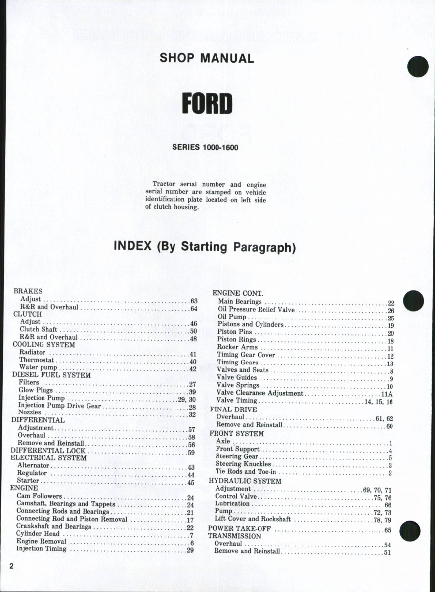
SHOP MANUAL
SERIES 1000-1600
Tractor serial number and engine
serial number are stamped on vehicle
identification plate located on left side
of clutch housing.
INDEX (By Starling Paragraph)
BRAKES
Adjust 63
R&R and Overhaul 54
CLUTCH
Adjust 46
Clutch Shaft 50
R&R and Overhaul 48
COOLING SYSTEM
Radiator 41
Thermostat 40
Water pump 42
DIESEL FUEL SYSTEM
Filters 27
Glow Plugs 39
Injection Pump 29, 30
Injection Pump Drive Gear 28
Nozzles 32
DIFFERENTIAL
Adjustment 57
Overhaul 58
Removie and Reinstall 56
DIFFERENTIAL LOCK 59
ELECTRICAL SYSTEM
Alternator 43
Regulator 44
Starter 45
ENGINE
Cam Followers 24
Camshaft, Bearings and Tappets 24
Connecting Rods and Bearings 21
Connecting Rod and Piston Removal 17
Crankshaft and Bearings [ .22
Cylinder Head 7
Engine Removal 6
Injection Timing 29
ENGINE CONT.
Main Bearings
Oil Pressure Relief Valve ...
Oil Pump
Pistons and Cylinders
Piston Pins
Piston Rings
Rocker Arms
Timing Gear Cover
Timing Gears
Valves and Seats
Valve Guides
Valve Springs
Valve Clearance Adjustment.
Valve Timing
FINAL DRIVE
Overhaul
Remove and Reinstall
FRONT SYSTEM
Axle
Front Support
Steering Gear
Steering Knuckles
Tie Rods and Toe in
HYDRAULIC SYSTEM
Adjustment
Control Valve
Lubrication
Pump
Lift Cover and Rockshaft
POWER TAKE OFF
TRANSMISSION
Overhaul
Remove and Reinstall
22
26
25
19
20
18
11
12
13
8
9
10
llA
.14. 15, 16
.61,62
.... 60
.1
.4
.5
.3
.2
.69, 70, 71
. ..75, 76
66
.... 72,73
.... 78.79
65
.54
.51
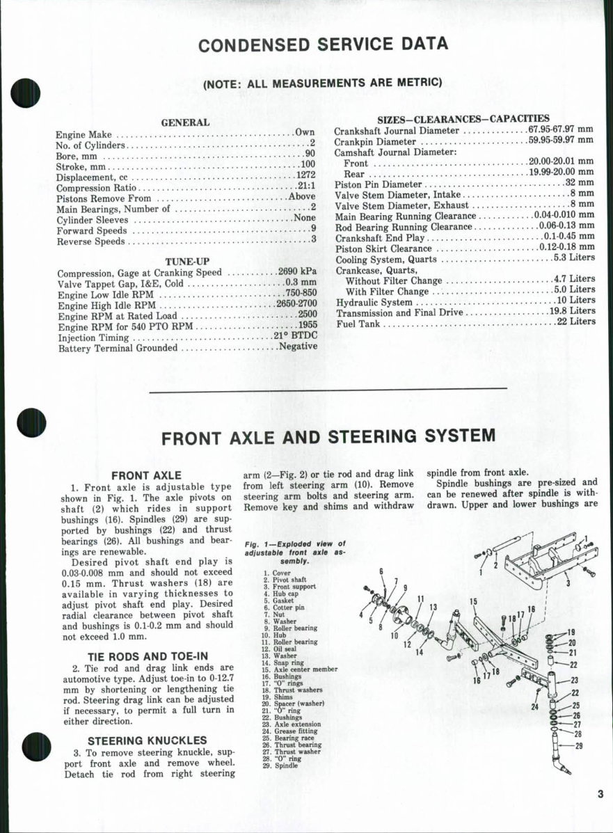
CONDENSED SERVICE DATA
(NOTE: ALL MEASUREMENTS ARE METRIC)
GENERAL
Engine Make Own
No. of Cylinders 2
Bore, mm ^^
Stroke, mm 100
Displacement, cc 1272
Compression Ratio 21:1
Pistons Remove From Above
Main Bearings, Number of 2
Cylinder Sleeves None
Forward Speeds 9
Reverse Speeds ^
TUNE-UP
Compression, Gage at Cranking Speed 2690 kPa
Valve Tappet Gap, I&E, Cold 0.3 mm
Engine Low Idle RPM 750-850
Engine High Idle RPM 2650-2700
Engine RPM at Rated Load • 2500
Engine RPM for 540 PTO RPM 1955
Injection Timing 21° BTDC
Battery Terminal Grounded Negative
SIZES-CLEARANCES-CAPACrriES
Crankshaft Journal Diameter 67.95-67.97 mm
Crankpin Diameter 59.95-59.97 mm
Camshaft Journal Diameter:
Front 20.00 20.01 mm
Rear . ! . * ' . . 19.99-20.00 mm
Piston Pin Diameter 32 mm
Valve Stem Diameter, Intake 8 mm
Valve Stem Diameter, Exhaust 8 mm
Main Bearing Running Clearance 0.04-0.010 mm
Rod Bearing Running Clearance 0.06-0.13 mm
Crankshaft End Play 0.1-0.45 mm
Piston Skirt Clearance 0.12-0.18 mm
Cooling System, Quarts 5.3 Liters
Crankcase, Quarts,
Without Filter Change 4.7 Liters
With Filter Change 5.0 Liters
Hydraulic System 10 Liters
Transmission and Final Drive 19.8 Liters
Fuel Tank 22 Liters
FRONT AXLE AND STEERING SYSTEM
FRONT AXLE
1. Front axle is adjustable type
shown in Fig. 1. The axle pivots on
shaft (2) which rides in support
bushings (16). Spindles (29) are sup-
ported by bushings (22) and thrust
bearings (26). All bushings and bear-
ings are renewable.
Desired pivot shaft end play is
0.03-0.008 mm and should not exceed
0.15 mm. Thrust washers (18) are
available in varying thicknesses to
adjust pivot shaft end play. Desired
radial clearance between pivot shaft
and bushings is 0.1-0.2 mm and should
not ekeeed 1.0 mm.
TIE RODS AND TOE-IN
2. Tie rod and drag link ends are
automotive type. Adjust toe-in to 0-12.7
mm by shortening or lengthening tie
rod. Steering drag link can be adjusted
if necessary, to permit a full turn in
either direction.
STEERING KNUCKLES
3. To remove steering knuckle, sup-
port front axle and remove wheel.
Detach tie rod from right steering
arm (2—Fig. 2) or tie rod and drag link
from left steering arm (10). Remove
steering arm bolts and steering arm.
Remove key and shims and withdraw
spindle from front axle.
Spindle bushings are pre-sized and
can be renewed after spindle is with-
drawn. Upper and lower bushings are
fig, t~Explod9d view of
adiustable front axte as-
sembly.
1. Cover
2. Pivot shaft
3. Front support
4. Hub cap
5. Gasket
6. Cotter pin
7. Nut
8. Washer
9. Roller bearing
10. Hub
11. Roller bearing
12. Oil seal
13. Washer
14. Snap ring
15. Axle center member
16. Bushings
17. "0" rings
18. Thrust washers
19. Shims
20. Spacer (washer)
21. "0" ring
22. Bushings
23. Axle extension
24. Grease fitting
25. Bearing race
26. Thrust bearing
27. Thrust washer
28. "0" ring
29. Spindle
Paragraphs 4-7
interchangeable. Install sufficient shims
(19—Fig. 1) to fill gap between steering
arm and spacer (20).
FORD
10
12
Fig. 2-^Expioded view of steering linkage.
1. Key
2. Steering arm, R.H.
3. Tie rod end
4. Tie rod extension
5. Pitman arm
6. Drag link end
7. Drag link
8. Tie rod
9. Drag link end
10. Steering arm, L.H.
11. Key
12. Tie rod end
FRONT SUPPORT
4. To remove front support, remove
hood, drain cooling system, disconnect
radiator hose and remove radiator.
Detach drag link from pitman arm and
place a support under clutch housing.
Unscrew twelve screws securing front
support to sides of engine, and roll
front axle assembly away from tractor.
Separate front support from front axle.
STEERING GEAR
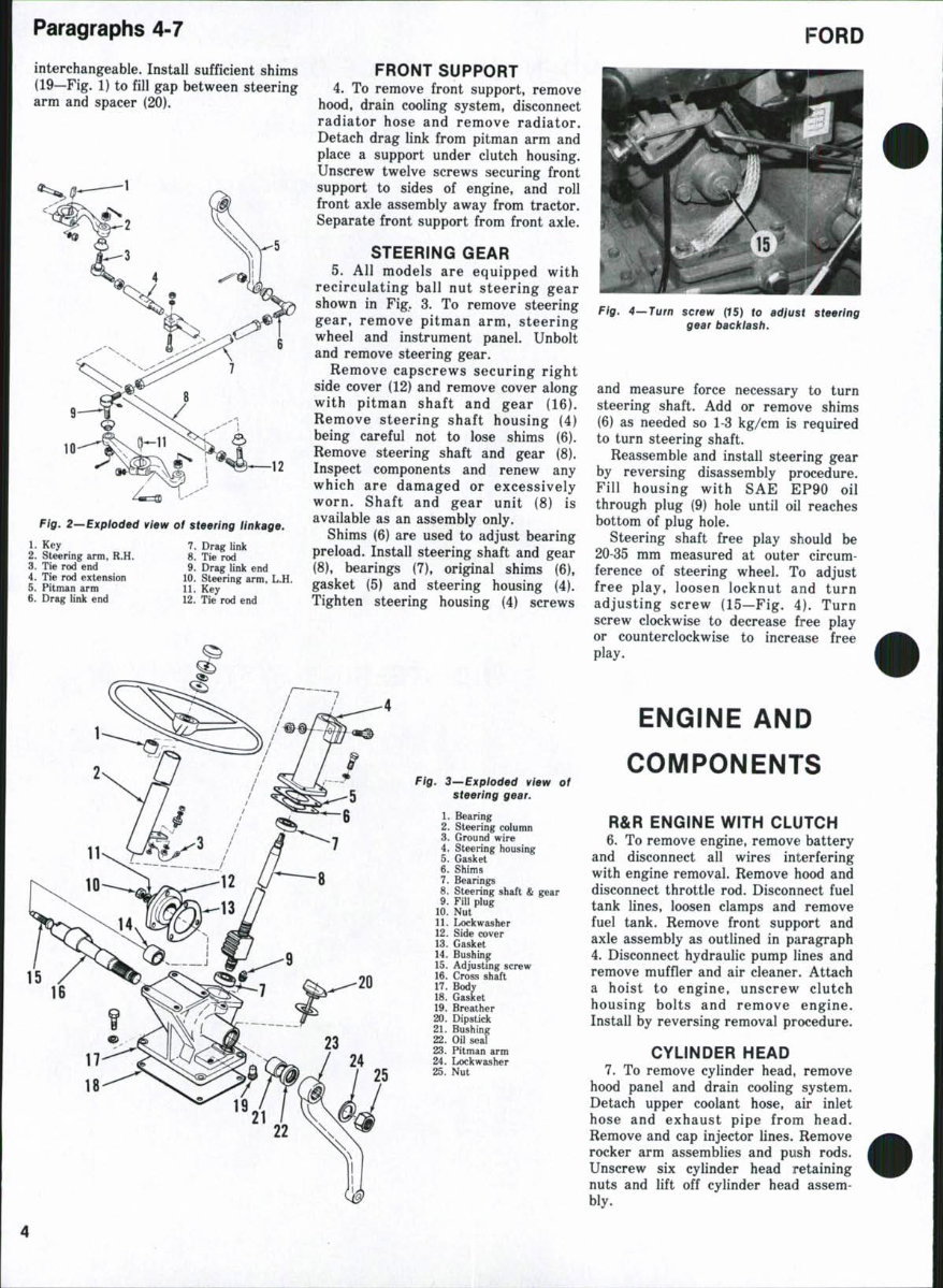
5. All models are equipped with
recirculating ball nut steering gear
shown in Fig. 3. To remove steering
gear, remove pitman arm, steering
wheel and instrument panel. Unbolt
and remove steering gear.
Remove capscrews securing right
side cover (12) and remove cover along
with pitman shaft and gear (16).
Remove steering shaft housing (4)
being careful not to lose shims (6).
Remove steering shaft and gear (8).
Inspect components and renew any
which are damaged or excessively
worn. Shaft and gear unit (8) is
available as an assembly only.
Shims (6) are used to adjust bearing
preload. Install steering shaft and gear
(8), bearings (7), original shims (6),
gasket (5) and steering housing (4).
Tighten steering housing (4) screws
Fig. 3—Expioded view of
steering gear.
1. Bearing
2. Steering column
3. Ground wire
4. Steering housing
5. Gasket
6. Shims
7. Bearings
8. Steering shaft & gear
9. Fill plug
10. Nut
11. Lockwasher
12. Side cover
13. Gasket
14. Bushing
15. Adjusting screw
16. Cross shaft
17. Body
18. Gasket
19. Breather
20. Dipstick
21. Bushing
22. Oil seal
23. Pitman arm
24. Lockwasher
25. Nut
Fig. 4—Turn screw {IS) to adjust steering
gear baciciash.
and measure force necessary to turn
steering shaft. Add or remove shims
(6) as needed so 1-3 kg/cm is required
to turn steering shaft.
Reassemble and install steering gear
by reversing disassembly procedure.
Fill housing with SAE EP90 oil
through plug (9) hole until oil reaches
bottom of plug hole.
Steering shaft free play should be
20-35 mm measured at outer circum-
ference of steering wheel. To adjust
free play, loosen locknut and turn
adjusting screw (15—Fig. 4). Turn
screw clockwise to decrease free play
or counterclockwise to increase free
play.
ENGINE AND
COMPONENTS
R&R ENGINE WITH CLUTCH
6. To remove engine, remove battery
and disconnect all wires interfering
with engine removal. Remove hood and
disconnect throttle rod. Disconnect fuel
tank lines, loosen clamps and remove
fuel tank. Remove front support and
axle assembly as outlined in paragraph
4. Disconnect hydraulic pump lines and
remove muffler and air cleaner. Attach
a hoist to engine, unscrew clutch
housing bolts and remove engine.
Install by reversing removal procedure.
CYLINDER HEAD
7. To remove cylinder head, remove
hood panel and drain cooling system.
Detach upper coolant hose, air inlet
hose and exhaust pipe from head.
Remove and cap injector lines. Remove
rocker arm assemblies and push rods.
Unscrew six cylinder head retaining
nuts and lift off cylinder head assem-
bly.
1000-1600 Paragraphs 8-16
NOTE: One cylinder head retaining
nut is iocated in air inlet passage.
Cylinder heat warpage should not
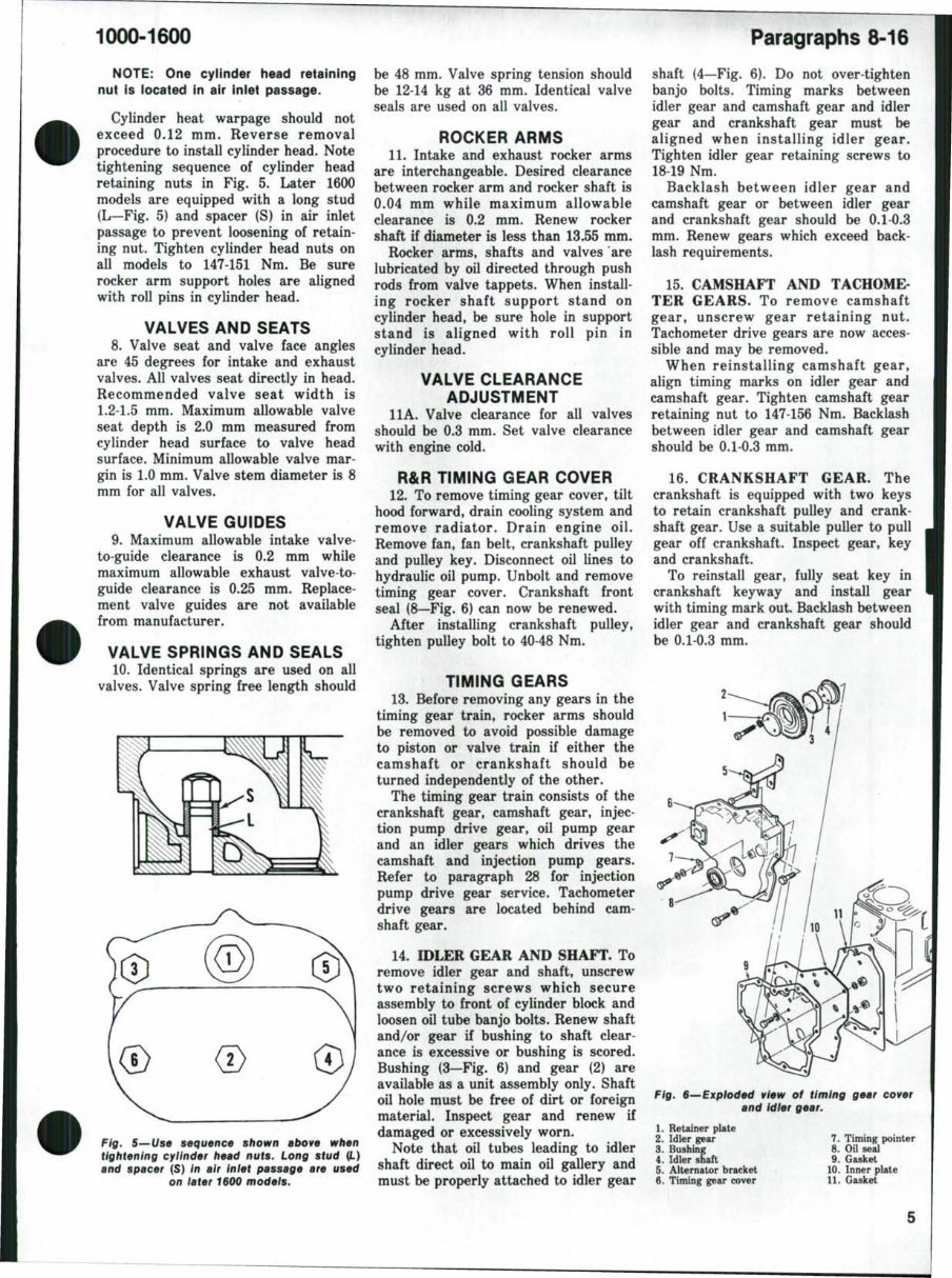
exceed 0.12 mm. Reverse removal
procedure to install cylinder head. Note
tightening sequence of cylinder head
retaining nuts in Fig. 5. Later 1600
models are equipped with a long stud
(L—Fig. 5) and spacer (S) in air inlet
passage to prevent loosening of retain-
ing nut. Tighten cylinder head nuts on
all models to 147-151 Nm. Be sure
rocker arm support holes are aligned
with roll pins in cylinder head.
VALVES AND SEATS
8. Valve seat and valve face angles
are 45 degrees for intake and exhaust
valves. All valves seat directly in head.
Recommended valve seat width is
1.2-1.5 mm. Maximum allowable valve
seat depth is 2.0 mm measured from
cylinder head surface to valve head
surface. Minimum allowable valve mar-
gin is 1.0 mm. Valve stem diameter is 8
mm for all valves.
VALVE GUIDES
9. Maximum allowable intake valve-
to-guide clearance is 0.2 mm while
maximum allowable exhaust valve-to-
guide clearance is 0.25 mm. Replace-
ment valve guides are not available
from manufacturer.
VALVE SPRINGS AND SEALS
10. Identical springs are used on all
valves. Valve spring free length should
Fig. 5—Use sequence sfiown above when
tightening cyiinder head nuts. Long stud (L)
and spacer (S) in air iniet passage are used
on later 1600 modeis.
be 48 mm. Valve spring tension should
be 12-14 kg at 36 mm. Identical valve
seals are used on all valves.
ROCKER ARMS
11. Intake and exhaust rocker arms
are interchangeable. Desired clearance
between rocker arm and rocker shaft is
0.04 mm while maximum allowable
clearance is 0.2 mm. Renew rocker
shaft if diameter is less than 13.55 mm.
Rocker arms, shafts and valves are
lubricated by oil directed through push
rods from valve tappets. When install-
ing rocker shaft support stand on
cylinder head, be sure hole in support
stand is aligned with roll pin in
cylinder head.
VALVE CLEARANCE
ADJUSTMENT
11 A. Valve clearance for all valves
should be 0.3 mm. Set valve clearance
with engine cold.
R&R TIMING GEAR COVER
12. To remove timing gear cover, tilt
hood forward, drain cooling system and
remove radiator. Drain engine oil.
Remove fan, fan belt, crankshaft pulley
and pulley key. Disconnect oil lines to
hydraulic oil pump. Unbolt and remove
timing gear cover. Crankshaft front
seal (8—Fig. 6) can now be renewed.
After installing crankshaft pulley,
tighten pulley bolt to 40-48 Nm.
TIMING GEARS
13. Before removing any gears in the
timing gear train, rocker arms should
be removed to avoid possible damage
to piston or valve train if either the
camshaft or crankshaft should be
turned independently of the other.
The timing gear train consists of the
crankshaft gear, camshaft gear, injec-
tion pump drive gear, oil pump gear
and an idler gears which drives the
camshaft and injection pump gears.
Refer to paragraph 28 for injection
pump drive gear service. Tachometer
drive gears are located behind cam-
shaft gear.
14. IDLER GEAR AND SHAFT. To
remove idler gear and shaft, unscrew
two retaining screws which secure
assembly to front of cylinder block and
loosen oil tube banjo bolts. Renew shaft
and/or gear if bushing to shaft clear-
ance is excessive or bushing is scored.
Bushing (3—Fig. 6) and gear (2) are
available as a unit assembly only. Shaft
oil hole must be free of dirt or foreign
material. Inspect gear and renew if
damaged or excessively worn.
Note that oil tubes leading to idler
shaft direct oil to main oil gallery and
must be properly attached to idler gear
shaft (4—Fig. 6). Do not over-tighten
banjo bolts. Timing marks between
idler gear and camshaft gear and idler
gear and crankshaft gear must be
aligned when installing idler gear.
Tighten idler gear retaining screws to
18-19 Nm.
Backlash between idler gear and
camshaft gear or between idler gear
and crankshaft gear should be 0.1-0.3
mm. Renew gears which exceed back-
lash requirements.
15. CAMSHAFT AND TACHOME-
TER GEARS. To remove camshaft
gear, unscrew gear retaining nut.
Tachometer drive gears are now acces-
sible and may be removed.
When reinstalling camshaft gear,
align timing marks on idler gear and
camshaft gear. Tighten camshaft gear
retaining nut to 147-156 Nm. Backlash
between idler gear and camshaft gear
should be 0.1-0.3 mm.
16. CRANKSHAFT GEAR. The
crankshaft is equipped with two keys
to retain crankshaft pulley and crank-
shaft gear. Use a suitable puller to pull
gear off crankshaft. Inspect gear, key
and crankshaft.
To reinstall gear, fully seat key in
crankshaft keyway and install gear
with timing mark out. Backlash between
idler gear and crankshaft gear should
be 0.1-0.3 mm.
Fig. e—Expioded view of timing gear cover
and idier gear.
1. Retainer plate
2. Idler gear
3. Bushing
4. Idler shaft
5. Alternator bracket
6. Timing gear cover
7. Timing pointer
8. Oil seal
9. Gasket
10. Inner plate
11. Gasket
Paragraphs 17-23 FORD
CONNECTING ROD AND
PISTON UNITS
17. Connecting rod and piston units
are removed from above after remov-
ing the cylinder head and oil pan. Be
sure to remove top ridge from cylinder
bores before attempting to withdraw
assemblies. Connecting rods should be
marked so assembly can be reinstalled
in original cylinder.
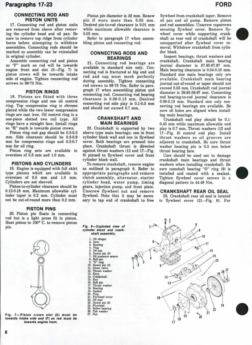
Assemble connecting rod and piston
so "F" mark on rod will be towards
engine front and slot (S—Fig. 7) in
piston crown will be towards intake
side of engine. Tighten connecting rod
screws to 69-73 Nm.
PISTON RINGS
18. Pistons are fitted with three
compression rings and one oil control
ring. Top compression ring is chrome
plated while the two lower compression
rings are cast iron. Oil control ring is a
one-piece slotted two rail type. All
rings have a straight face. Install rings
so "R" mark is towards piston crown.
Piston ring end gap should be 0.3-0.5
mm. Side clearance should be 0.3-0.9
mm for compression rings and 0.3-0.7
mm for oil ring.
Piston ring sets are available in
oversizes of 0.5 mm and 1.0 mm.
PISTONS AND CYLINDERS
19. Engine is equipped with full skirt
type pistons which are available in
oversizes of 0.5 mm and 1.0 mm.
Cylinders are not sleeved.
Piston-to-cylinder clearance should be
0.12-0.18 mm. Maximum allowable cyl-
inder taper is 0.2 mm. Cylinder must
not be out-of-round more than 0.2 mm.
PISTON PINS
20. Piston pin floats in connecting
rod but is a light press fit in piston.
Heat piston to 100*^ C. to remove piston
pin.
Piston pin diameter is 32 mm. Renew
pin if worn more than 0.05 mm.
Desired pin-to-rod clearance is 0.01 mm
while maximum allowable clearance is
0.05 mm.
Refer to paragraph 17 when assem-
bling piston and connecting rod.
CONNECTING RODS AND
BEARINGS
21. Connecting rod bearings are
available in standard size only. Con-
necting rod is fractured at big end and
rod and cap must mesh perfectly
during assembly. Tighten connecting
rod screws to 69-73 Nm. Refer to para-
graph 17 when assembling piston and
connecting rod. Connecting rod bearing
clearance is 0.06-0.13 mm. Desired
connecting rod side play is 0.1-0.3 mm
and should not exceed 0.7 mm.
CRANKSHAFT AND
MAIN BEARINGS
22. Crankshaft is supported by two
sleeve type main bearings; one in front
cylinder block wall and one in flywheel
cover. Both bearings are pressed into
place. Crankshaft thrust is directed
against thrust washers (12 and 17—Fig.
8) pinned to flywheel cover and front
cylinder block wall.
To remove crankshaft, remove engine
as outlined in paragraph 6. Refer to
appropriate paragraphs and remove
clutch assembly, alternator, starter
cylinder head, water pump, timing
gears, injection pump, and front plate.
Unscrew flywheel nut and remove
flywheel. Note that it may be neces-
sary to tap end of crankshaft to free
Fig. l—Piston crown siot (S) must be
towards intake side and (F) on rod must be
towards engine front.
Fig. B^Expioded view of
cyiinder biock and crank-
shaft assembiy.
1. Oil slinger
2. Gear
S. Bearing
4. Plug
5. Oil pan
6. Dowel pin (2)
7. Oil pressure sensor
8. Roll pin
9. "0" ring
10. Dowel pin (2)
11. Drain valve
12. Thrust washer
13. Keys
14. Crankshaft
15. Kev
16. RoU pin
17. Thrust washer
18. Bearing
19. Gasket
20. Plug
21. Flywheel cover
22. Oil seal
23. Dowel pin (2)
24. Flywheel
25. Roller bearing
26. Tab washer
27. Nut
flywheel from crankshaft taper. Remove
oil pan and oil pump. Remove piston
and rod assemblies. Unscrew capscrews
securing flywheel cover. Remove fly-
wheel cover while supporting crank-
shaft as rear end of crankshaft will be
unsupported after flywheel cover re-
mo vial. Withdraw crankshaft from cylin-
der block.
Inspect bearings, thrust washers and
crankshaft. Crankshaft main bearing
journal diameter is 67.95-67.97 mm.
Main bearing clearance is 0.04-0.10 mm.
Standard size main bearings only are
available. Crankshaft main bearing
journal out-of-round or taper should not
exceed 0.05 mm. Crankshaft rod journal
diameter is 59.95-59.97 mm. Connecting
rod bearing-to-rod journal clearance is
0.06-0.13 mm. Standard size only con-
necting rod bearings are available. Be
sure oil holes are aligned when install-
ing main bearings.
Crankshaft end play should be 0.1-
0.45 mm while maximum allowable end
play is 0.7 mm. Thrust washers (12 and
17—Fig. 8) control end play. Install
thrust washers so oil grooves are
adjacent to crankshaft. Be sure thrust
washer locating pin is 0.5 mm below
thrust bearing face.
Care should be used not to damage
crankshaft main bearings and thrust
washers when installing crankshaft. Be
sure camshaft bearing "0" ring (9) is
installed and coated with a sealant.
Tighten flywheel cover screws in a
diagonal pattern to 44-48 Nm.
CRANKSHAFT REAR OIL SEAL
23. Crankshaft rear oil seal is located
in flywheel cover (21—Fig. 8). For
24
H < 21
t9 20
22
1000-1600
access to rear oil seal, remove flywheel
cover as outlined in paragraph 22.
CAMSHAFT, BEARINGS
AND TAPPETS
24. Camshaft rides in two ball bear-
ings located in front and rear cylinder
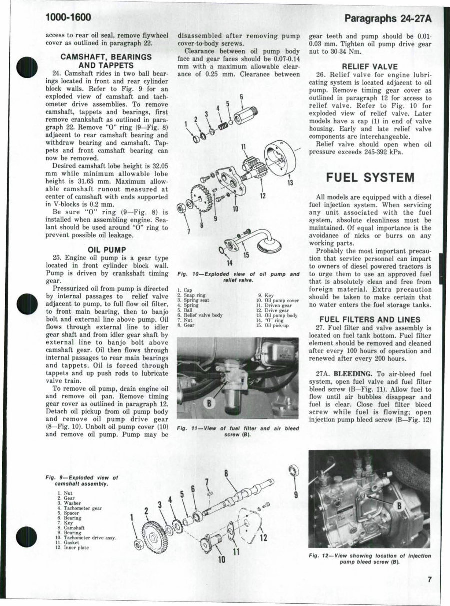
block walls. Refer to Fig. 9 for an
exploded view of camshaft and tach-
ometer drive assemblies. To remove
camshaft, tappets and bearings, first
remove crankshaft as outlined in para-
graph 22. Remove "0" ring (9—Fig. 8)
adjacent to rear camshaft bearing and
withdraw bearing and camshaft. Tap-
pets and front camshaft bearing can
now be removed.
Desired camshaft lobe height is 32.05
mm while minimum allowable lobe
height is 31.65 mm. Maximum allow-
able camshaft runout measured at
center of camshaft with ends supported
in V-blocks is 0.2 mm.
Be sure "0" ring (9—Fig. 8) is
installed when assembling engine. Sea-
lant should be used around "0" ring to
prevent possible oil leakage.
OIL PUMP
25. Engine oil pump is a gear type
located in front cylinder block wall.
Pump is driven by crankshaft timing
gear.
Pressurized oil from pump is directed
by internal passages to relief valve
adjacent to pump, to full flow oil filter,
to front main bearing, then to banjo
bolt and external line above pump. Oil
flows through external line to idler
gear shaft and from idler gear shaft by
external line to banjo bolt above
camshaft gear. Oil then flows through
internal passages to rear main bearings
and tappets. Oil is forced through
tappets and up push rods to lubricate
valve train.
To remove oil pump, drain engine oil
and remove oil pan. Remove timing
gear cover as outlined in paragraph 12.
Detach oil pickup from oil pump body
and remove oil pump drive gear
(8—Fig. 10). Unbolt oil pump cover (10)
and remove oil pump. Pump may be
disassembled after removing pump
cover to-body screws.
Clearance between oil pump body
face and gear faces should be 0.07-0.14
mm with a maximum allowable clear-
ance of 0.25 mm. Clearance between
Fig. lO^Exploded view of oii pump and
reiief valve.
1. Cap
2. Snap ring
3. Sprmg seat
4. Spring
5. Ball
6. Relief valve body
7. Nut
8. Gear
9. Key
10. Oil pump cover
11. Driven gear
12. Drive gear
13. Oil pump body
14. "0" ring
15. Oil pick up
Paragraphs 24-27A
gear teeth and pump should be 0.01-
0.03 mm. Tighten oil pump drive gear
nut to 30 34 Nm.
RELIEF VALVE
26. Relief valve for engine lubri-
cating system is located adjacent to oil
pump. Remove timing gear cover as
outlined in paragraph 12 for access to
relief valve. Refer to Fig. 10 for
exploded view of relief valve. Later
models have a cap (1) in end of valve
housing. Early and late relief valve
components are interchangeable.
Relief valve should open when oil
pressure exceeds 245-392 kPa.
FUEL SYSTEM
All models are equipped with a diesel
fuel injection system. When servicing
any unit associated with the fuel
system, absolute cleanliness must be
maintained. Of equal importance is the
avoidance of nicks or burrs on any
working parts.
Probably the most important precau-
tion that service personnel can impart
to owners of diesel powered tractors is
to urge them to use an approved fuel
that is absolutely clean and free from
foreign material. Extra precaution
should be taken to make certain that
no water enters the fuel storage tanks.
FUEL FILTERS AND LINES
27. Fuel filter and valve assembly is
located on fuel tank bottom. Fuel filter
element should be removed and cleaned
after every 100 hours of operation and
renewed after every 200 hours.
27A. BLEEDING. To air bleed fuel
system, open fuel valve and fuel filter
bleed screw (B—Fig. 11). Allow fuel to
flow until air bubbles disappear and
fuel is clear. Close fuel filter bleed
screw while fuel is flowing; open
injection pump bleed screw (B—Fig. 12)
Fig. H^View of fuel fiiter and air bleed
screw (6).
Fig. 9^ Expioded view of
camshaft assembiy.
1. Nut
2. Gear
3. Washer
4. Tachometer gear
5. Spacer
6. Bearing
7. Key
8. Camshaft
9. Bearing
10. Tachometer drive assy.
11. Gasket
12. Inner plate
12
Fig. 12^View showing location of injection
pump bleed screw (B).
Paragraphs 28-31
and allow fuel to flow until air bubbles
disappear, then close bleed screw.
Loosen high pressure fuel lines at
injectors, open throttle and crank
engine until fuel escapes from loosened
fuel line connections. Tighten fuel line
compression nuts.
INJECTION PUMP DRIVE GEAR
28. To remove injection pump drive
gear, remove timing cover as outlined
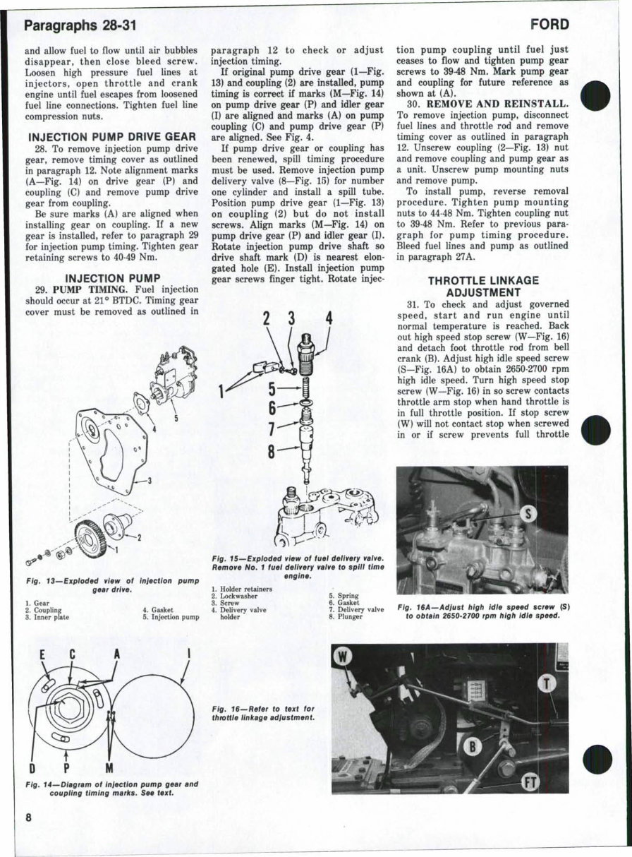
in paragraph 12. Note alignment marks
(A—Fig. 14) on drive gear (P) and
coupling (C) and remove pump drive
gear from coupling.
Be sure marks (A) are aligned when
installing gear on coupling. If a new
gear is installed, refer to paragraph 29
for injection pump timing. Tighten gear
retaining screws to 40-49 Nm.
INJECTION PUMP
29. PUMP TIMING. Fuel injection
should occur at 21 *» BTDC. Timing gear
cover must be removed as outlined in
Fig. IS—Expioded view of injection pump
gear drive.
1. Gear
2. Coupling 4. Gasket
3. Inner plate 5. Injection pump
paragraph 12 to check or adjust
injection timing.
If original pump drive gear (1—Fig.
13) and coupling (2) are installed, pump
timing is correct if marks (M—Fig. 14)
on pump drive gear (P) and idler gear
(I) are aligned and marks (A) on pump
coupling (C) and pump drive gear (P)
are aligned. See Fig. 4.
If pump drive gear or coupling has
been renewed, spill timing procedure
must be used. Remove injection pump
delivery valve (8—Fig. 15) for number
one cylinder and install a spill tube.
Position pump drive gear (1—Fig. 13)
on coupling (2) but do not install
screws. Align marks (M—Fig. 14) on
pump drive gear (P) and idler gear (I).
Rotate injection pump drive shaft so
drive shaft mark (D) is nearest elon-
gated hole (E). Install injection pump
gear screws finger tight. Rotate injec-
2 3
Fig. 15—Exploded view of fuel delivery valve.
Remove No. 1 fuel deiivery vaive to spiii time
engine.
FORD
tion pump coupling until fuel just
ceases to flow and tighten pump gear
screws to 3948 Nm. Mark pump gear
and coupling for future reference as
shown at (A).
30. REMOVE AND REINSTALL.
To remove injection pump, disconnect
fuel lines and throttle rod and remove
timing cover as outlined in paragraph
12. Unscrew coupling (2—Fig. 13) nut
and remove coupling and pump gear as
a unit. Unscrew pump mounting nuts
and remove pump.
To install pump, reverse removal
procedure. Tighten pump mounting
nuts to 44-48 Nm. Tighten coupling nut
to 39-48 Nm. Refer to previous para-
graph for pump timing procedure.
Bleed fuel lines and pump as outlined
in paragraph 27A.
THROTTLE LINKAGE
ADJUSTMENT
31. To check and adjust governed
speed, start and run engine until
normal temperature is reached. Back
out high speed stop screw (W—Fig. 16)
and detach foot throttle rod from bell
crank (B). Adjust high idle speed screw
(S—Fig. 16A) to obtain 2650-2700 rpm
high idle speed. Turn high speed stop
screw (W—Fig. 16) in so screw contacts
throttle arm stop when hand throttle is
in full throttle position. If stop screw
(W) will not contact stop when screwed
in or if screw prevents full throttle
1. Holder retainers
2. Lockwasher
3. Screw
4. Delivery valve
holder
5. Spring
6. Gasket
7. Delivery valve
8. Plunger
Fig. ISA--Adjust high idie speed screw (S)
to obtain 2650-2700 rpm high idie speed.
Fig. 4—Diagram of injection pump gear and
coupiing timing marks. See text.
Fig. 16'-Refer to text for
throttie iinkage adjustment.
1000-1600
opening, turn throttle rod turnbuckle
(T) to shorten or lengthen throttle rod.
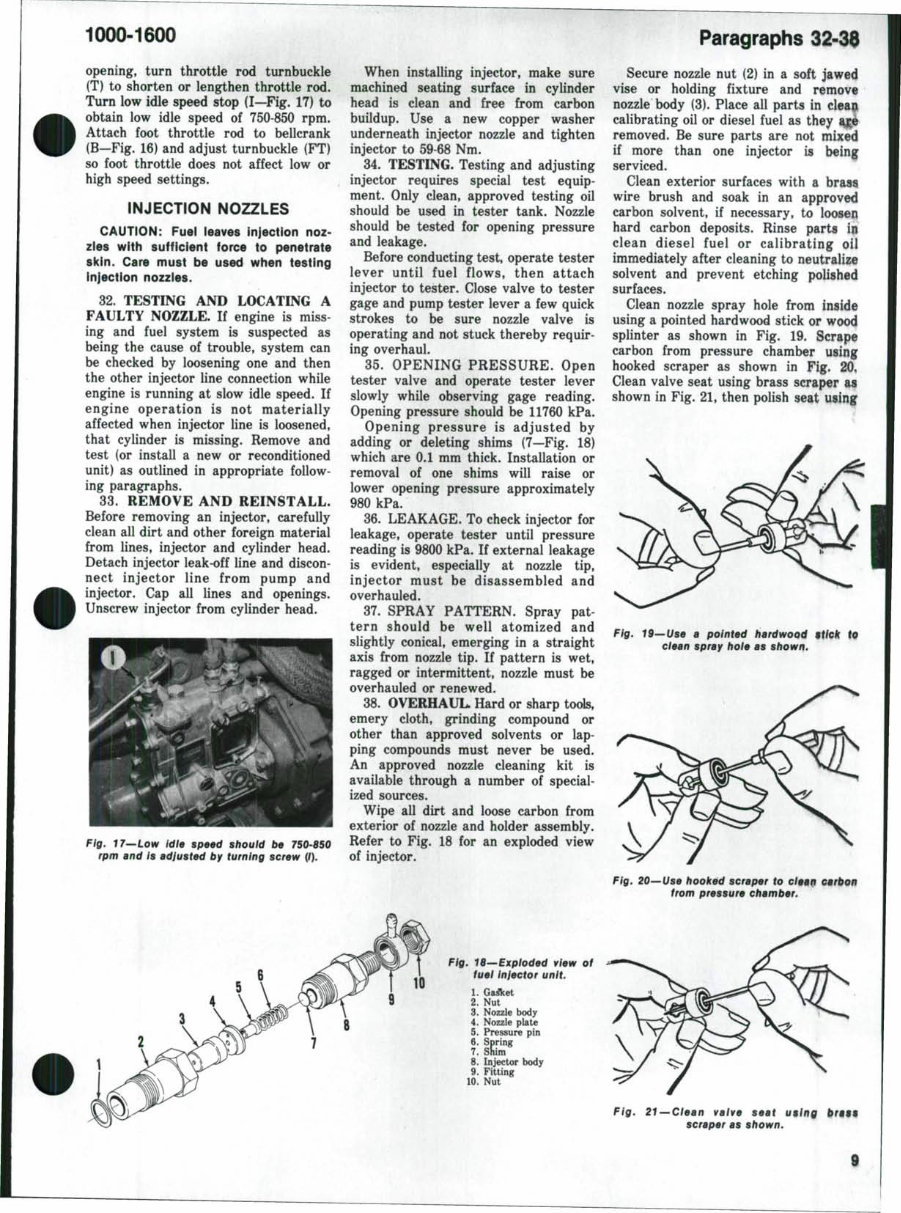
Turn low idle speed stop (I—Fig. 17) to
obtain low idle speed of 750-850 rpm.
Attach foot throttle rod to bellcrank
(B—Fig. 16) and adjust turnbuckle (FT)
so foot throttle does not affect low or
high speed settings.
INJECTION NOZZLES
CAUTION: Fuel leaves injection noz-
zles with sufficient force to penetrate
sicin. Care must be used when testing
injection nozzies.
32. TESTING AND LOCATING A
FAULTY NOZZLE. If engine is miss-
ing and fuel system is suspected as
being the cause of trouble, system can
be checked by loosening one and then
the other injector line connection while
engine is running at slow idle speed. If
engine operation is not materially
affected when injector line is loosened,
that cylinder is missing. Remove and
test (or install a new or reconditioned
unit) as outlined in appropriate follow-
ing paragraphs.
33. REMOVE AND REINSTALL.
Before removing an injector, carefully
clean all dirt and other foreign material
from lines, injector and cylinder head.
Detach injector leak-off line and discon-
nect injector line from pump and
injector. Cap all lines and openings.
Unscrew injector from cylinder head.
Fig. 17—Low idie speed shouid be 750-850
rpm and is adjusted by turning screw (/).
When installing injector, make sure
machined seating surface in cylinder
head is clean and free from carbon
buildup. Use a new copper washer
underneath injector nozzle and tighten
injector to 59-68 Nm.
34. TESTING. Testing and adjusting
injector requires special test equip-
ment. Only clean, approved testing oil
should be used in tester tank. Nozzle
should be tested for opening pressure
and leakage.
Before conducting test, operate tester
lever until fuel flows, then attach
injector to tester. Close valve to tester
gage and pump tester lever a few quick
strokes to be sure nozzle valve is
operating and not stuck thereby requir-
ing overhaul.
35. OPENING PRESSURE. Open
tester valve and operate tester lever
slowly while observing gage reading.
Opening pressure should be 11760 kPa.
Opening pressure is adjusted by
adding or deleting shims (7—Fig. 18)
which are 0.1 mm thick. Installation or
removal of one shims will raise or
lower opening pressure approximately
980 kPa.
36. LEAKAGE. To check injector for
leakage, operate tester until pressure
reading is 9800 kPa. If external leakage
is evident, especially at nozzle tip,
injector must be disassembled and
overhauled.
37. SPRAY PATTERN. Spray pat-
tern should be well atomized and
slightly conical, emerging in a straight
axis from nozzle tip. If pattern is wet,
ragged or intermittent, nozzle must be
overhauled or renewed.
38. OVERHAUL. Hard or sharp tools,
emery cloth, grinding compound or
other than approved solvents or lap-
ping compounds must never be used.
An approved nozzle cleaning kit is
available through a number of special-
ized sources.
Wipe all dirt and loose carbon from
exterior of nozzle and holder assembly.
Refer to Fig. 18 for an exploded view
of injector.
10
Fig. 18—Expioded view of
fuei injector unit.
1. Ga^et
2. Nut
3. Nozzle body
4. Nozzle plate
5. Pressure pin
6. Spring
7. Shim
8. Injector body
9. Fitting
10. Nut
Paragraphs 32-38
Secure nozzle nut (2) in a soft jawed
vise or holding fixture and remove
nozzle body (3). Place all parts in cleajf
calibrating oil or diesel fuel as they ig^
removed. Be sure parts are not mixed
if more than one injector is being
serviced.
Clean exterior surfaces with a bras4
wire brush and soak in an approved
carbon solvent, if necessary, to loosen
hard carbon deposits. Rinse parts in
clean diesel fuel or calibrating oil
immediately after cleaning to neutralize
solvent and prevent etching polished
surfaces.
Clean nozzle spray hole from inside
using a pointed hardwood stick or wood
splinter as shown in Fig. 19. Scrape
carbon from pressure chamber using
hooked scraper as shown in Fig. 20,
Clean valve seat using brass scraper as
shown in Fig. 21, then polish seat using
Fig. 19—Use a pointed hardwood Mtick to
dean spray hoie as shown.
Fig. 20—Use hooked scraper to c/Mfi
from pressure chamber.
Fig. 21 —dean vaive seat U9lng frrttf
scraper as shown.
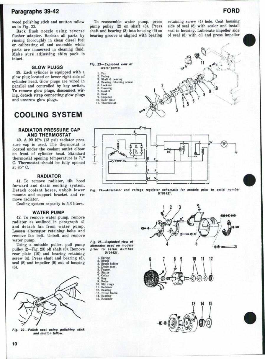
Paragraphs 39-42
wood polishing stick and mutton tallow
as in Fig. 22.
Back flush nozzle using reverse
flusher adapter. Reclean all parts by
rinsing thoroughly in clean diesel fuel
or calibrating oil and assemble while
parts are immersed in cleaning fluid.
Make sure adjusting shim pack is
intact.
GLOW PLUGS
39. Each cylinder is equipped with a
glow plug located on lower right side of
cylinder head. Glow plugs are wired in
parallel and controlled by key switch.
To remove glow plugs, disconnect wir-
ing, detach strap connecting glow plugs
and unscrew glow plugs.
COOLING SYSTEM
RADIATOR PRESSURE CAP
AND THERMOSTAT
40. A 90 kPa (13 psi) radiator pres-
sure cap is used. The thermostat is
located under the coolant outlet elbow
on front of cylinder head. Standard
thermostat opening temperature is 71**
C. Thermostat should be fully opened
at 85^ C.
RADIATOR
41. To remove radiator, tilt hood
forward and drain cooling system.
Detach coolant hoses, unbolt lower
mounts and support bracket and re-
move radiator.
Cooling system capacity is 5.3 liters.
WATER PUMP
42. To remove water pump, remove
radiator as outlined in paragraph 41
and detach fan from water pump.
Loosen alternator retaining bolts and
remove fan belt. Unbolt and remove
water pump.
Using a suitable puller, pull pump
pulley (2—Fig. 23) off shaft (3). Remove
rear plate (10) and bearing retaining
screw (4). Press shaft and bearing (3),
seal (8) and impeller (9) out of housing
(6).
To reassemble water pump, press
pump pulley (2) on shaft (3). Press
shaft and bearing (3) into housing (6) so
bearing groove is aligned with bearing
FORD
retaining screw (4) hole. Coat housing
side of seal (8) with sealer and install
seal in housing. Lubricate impeller side
of seal (8) with oil and press impeller
Fig. 23—Expioded view of
water pump.
1. Fan
2. PuUey
3. Shaft & bearing
4. Bearing retaining screw
5. Locknut
6. Housing
7. Gasket
8. Seal
9. Impeller
10. Rear plate
11. Thermostat
Fig. 24—Aiternator and voltage regulator schematic for modeis prior to serial number
U101421.
1 2 3
Fig. 25—Expioded view of
aiternator used on modeis
prior to seriai number
U101421.
1. Spring
2. Brush
3. Brush holder
4. Diode assy.
5. Frame
6. Stator
7. CoUar
8. Key
9. Rotor
10. Slip rings
11. Retainer
12. Bearing
13. Front frame
14. Bearing
15. Retainer
13
Fig. 22—Poiish seat using polishing stick
and mutton taliow.
10
1000-1600
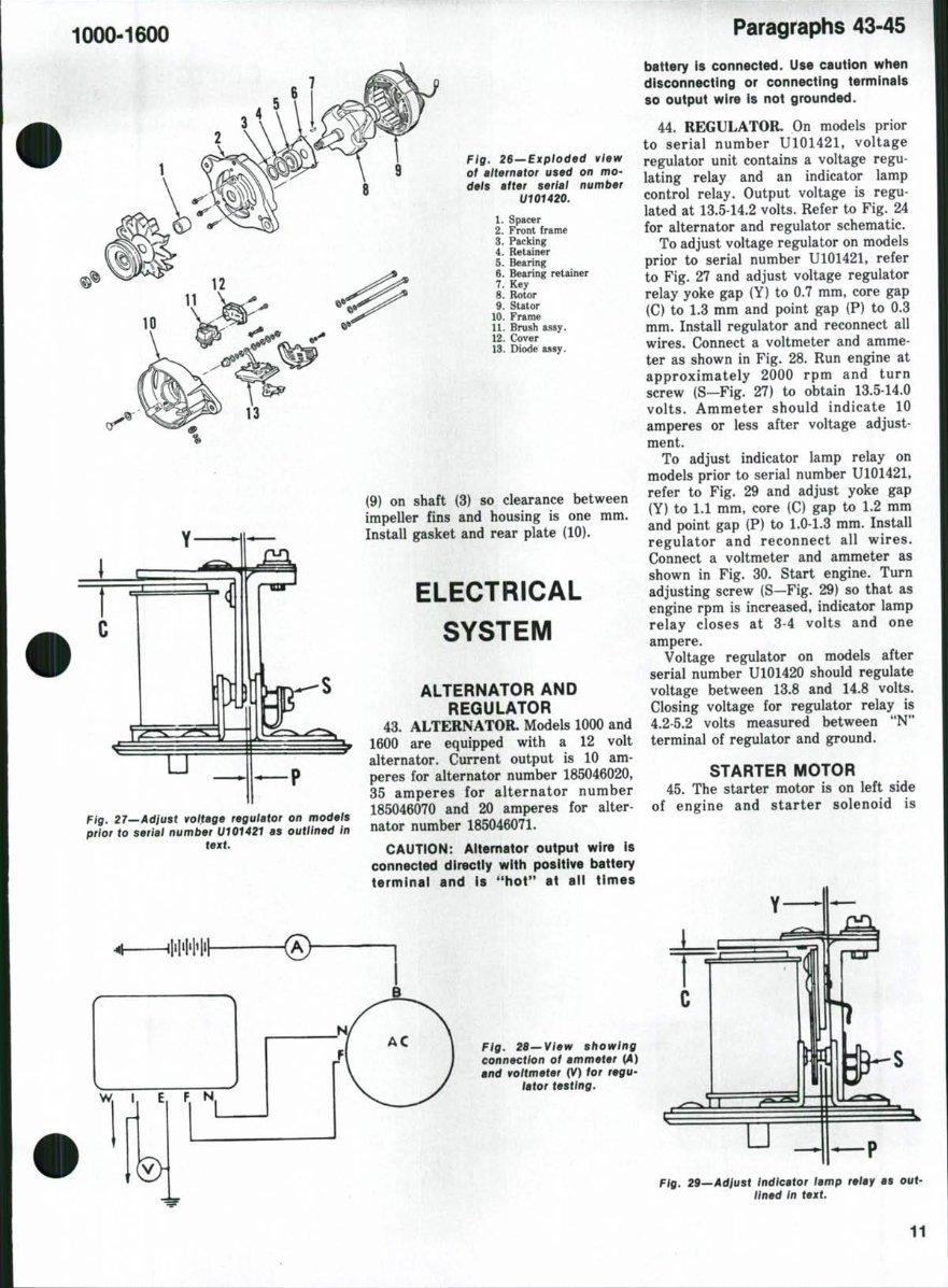
Fig, 26—Exploded view
of alternator used on mo-
deis after seriai number
U101420.
1. Spacer
2. Front frame
3. Packing
4. Retainer
5. Bearing
6. Bearing retainer
7. Key
8. Rotor
9. Stator
10. Frame
11. Brush assy.
12. Cover
13. Diode assy.
(9) on shaft (3) so clearance between
impeller fins and housing is one mm.
Install gasket and rear plate (10).
ELECTRICAL
SYSTEM
Fig. 27—Adjust voltage regulator on models
prior to seriai number U101421 as outlined in
text.
ALTERNATOR AND
REGULATOR
43. ALTERNATOR. Models 1000 and
1600 are equipped with a 12 volt
alternator. Current output is 10 am-
peres for alternator number 185046020,
35 amperes for alternator number
185046070 and 20 amperes for alter-
nator number 185046071.
CAUTION: Alternator output wire is
connected directly with positive battery
terminai and is "hot" at aii times
Paragraphs 43-45
battery is connected. Use caution when
disconnecting or connecting terminais
so output wire is not grounded.
44. REGULATOR. On models prior
to serial number U101421, voltage
regulator unit contains a voltage regu-
lating relay and an indicator lamp
control relay. Output voltage is regu-
lated at 13.5-14.2 volts. Refer to Fig. 24
for alternator and regulator schematic.
To adjust voltage regulator on models
prior to serial number U101421, refer
to Fig. 27 and adjust voltage regulator
relay yoke gap (Y) to 0.7 mm, core gap
(C) to 1.3 mm and point gap (P) to 0.3
mm. Install regulator and reconnect all
wires. Connect a voltmeter and amme-
ter as shown in Fig. 28. Run engine at
approximately 2000 rpm and turn
screw (S—Fig. 27) to obtain 13.5-14.0
volts. Ammeter should indicate 10
amperes or less after voltage adjust-
ment.
To adjust indicator lamp relay on
models prior to serial number U101421,
refer to Fig. 29 and adjust yoke gap
(Y) to 1.1 mm, core (C) gap to 1.2 mm
and point gap (P) to 1.0-1.3 mm. Install
regulator and reconnect all wires.
Connect a voltmeter and ammeter as
shown in Fig. 30. Start engine. Turn
adjusting screw (S—Fig. 29) so that as
engine rpm is increased, indicator lamp
relay closes at 3-4 volts and one
ampere.
Voltage regulator on models after
serial number U101420 should regulate
voltage between 13.8 and 14.8 volts.
Closing voltage for regulator relay is
4.2-5.2 volts measured between "N"
terminal of regulator and ground.
STARTER MOTOR
45. The starter motor is on left side
of engine and starter solenoid is
Fig. 28—View showing
connection of ammeter (A)
and voitmeter (V) for regu-
iator testing.
Fig. 29—Adjust indicator lamp relay as out-
lined in text.
11
You're Reading a Preview
What's Included?
 Lifetime Access
Fast Download Speeds
Online & Offline Access
Access PDF Contents & Bookmarks
Full Search Facility
Print one or all pages of your manual
$32.99
Ford Series 1000-1600 Tractors OEM Service & Repair Manual
Viewed 40 Times Today

What's Included?
Lifetime Access
Fast Download Speeds
Online & Offline Access
Access PDF Contents & Bookmarks
Full Search Facility
Print one or all pages of your manual
$32.99

Secure transaction
What's Included?
Lifetime Access
Fast Download Speeds
Online & Offline Access
Access PDF Contents & Bookmarks
Full Search Facility
Print one or all pages of your manual
Description
Ford Series 1000-1600 Tractors OEM Service & Repair Manual is a comprehensive guide designed explicitly for the maintenance and repair of Ford Series 1000-1600 tractors. It serves as an essential resource for both professional mechanics and DIY enthusiasts, providing detailed procedures and technical data to keep your tractor running at its optimum performance.
This manual is available in PDF format and is compatible with all versions of Windows and Mac operating systems. It includes in-depth coverage of important tractor systems including:
- Brakes
- Clutch
- Cooling System
- Diesel Fuel System
- Differential
- Electrical System
- Engine
- Final Drive
- Front System
- Hydraulic System
- Power Take-Off
- Transmission
- Wiring
Written in English, this manual requires Adobe Reader and WinZip for PDF access. It offers a cost-effective solution for maintaining your Ford Series 1000-1600 tractor's performance and reliability.


