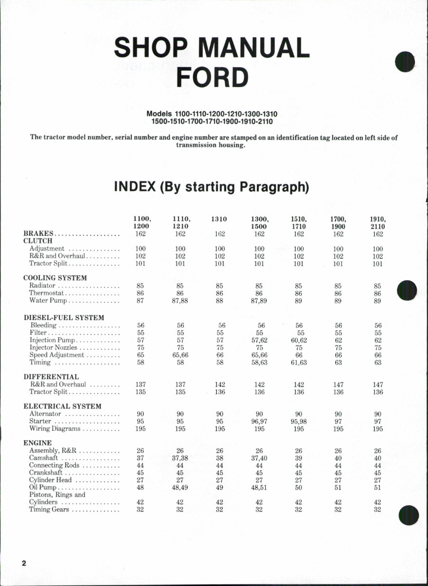
1100, 1200 FINALDRIVE 152 FRONT AXLE AND STEERING Axle (2 Wheel Drive) 1 Axle (4 Wheel Drive) 3 Manual Steering Gear 15 Power Steering HYDRAULIC SYSTEM Adjustments. 175 Control Valve 185 Filter 170 Lift Arm Housing 180 Pump 174 Testing 172 Trouble-Shooting 171 POWER TAKE-OFF 163 TRANSMISSION Hydrostatic Nonsynchromesh 105 Synchromesh INDEX (CONT.) 1110, 1210 152 1 8 15 175 185 170 180 174 173 171 1300 154 1 8 15 20 175 185 170 180 174 173 • 171 1300, 1500 154 1 3 15 175 185 170 180 174 172 171 1510, 1710 154, 156 1 8 15 20 175 185 170 180 174 172, 173 171 1700, 1900 158 1 3 15 20 175 185 170 180 174 172 171 1910, 2110 158 1 8 15 20 175 185,187 170 180 174 173 171 163 110 105 165 120 130 165 120 165 120 130 166 166 123, 12(> 126 130 DUAL DIMENSIONS This service manuai provides specifications in both the Metric (SI) and U.S. Customary systems of measurement. The first specification is given in the measuring system used during manufacture, whiie the second specification (given in parenthesis) is the converted measurement. For instance, a specification of "0.28 mm (0.011 inch)" wouid indicate that the equipment was manufactured using the metric system of measurement and the U.S. equivaient of 0.28 mm is 0.011 inch. CONDENSED SERVICE DATA 1100 GENERAL Engine Make Engine Model LEK752C2 Number of Cylinders 2 Bore 75 mm (2.95 in.) Stroke 80 mm (3.15 in.) Displacement 706 cc (43.1 cu. in.) Compression Ratio 23:1 TUNE-UP Firing Order 2-1 Valve Clearance-Cold Intake 0.30 mm (0.012 in.) Exhaust 0.30 mm (0.012 in.) Valve Face Angle Valve Seat Angle Injection Timing, Static-BTDC 23''-24° Injector Opening Pressure 11760 kPa (1705 psi) 1110 1200 1210 LEK757C 2 75 mm (2.95 in.) 80 mm (3.15 in.) 706 cc (43.1 cu. in.) 23:1 LEK802D 2 80 mm (3.15 in.) 80 mm (3.15 in.) 804 cc (49.1 cu. in.) 23:1 S723 3 72 mm (2.83 in.) 72 mm (2.83 in.) 879 cc (53.6 cu. in.) 24:1 2-1 0.20 mm (0.008 in.) 0.20 mm (0.008 in.) -45° -45° 2-1 0.30 mm (0.012 in.) 0.30 mm (0.012 in.) 11760 kPa (1705 psi) 11760 kPa (1705 psi) 1-2-3 0.20 mm (0.008 in.) 0.20 mm (0.008 in.) 24° 11760 kPa (1705 psi)
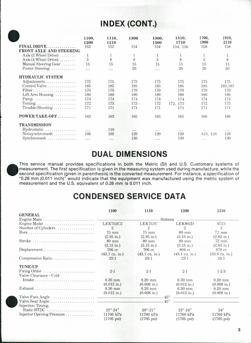
CONDENSED SERVICE DATA (CONT.) TUNE-UP (CONT.) Governed Speeds - Engine Rpm Low Idle 750-850 High Idle (No Load) 2750-2800 Rated (Full Load) 2600 Power Rating at Pto Shaft 8.2 kW (11 hp) Battery Volts Ground Polarity CAPACITIES Cooling System 3.0 L (3.2 U.S. qt.) Crankcase* 3,3 L (3.5 U.S. qt.) Fuel Tank 14 L (3.7 U.S. gal.) Standard Transmission & Rear Axle 18.9 L (20 U.S. qt.) Hydrostatsic Transmission & Rear Axle Front Axle Differential Case 1.5 L (1.6 U.S. qt) Front Axle Reduction Case(Each) 0.2 L (0.21 U.S. qt) *With filter change. SPECIAL TORQUES Connecting Rod Caps 24-27 N-m (18-20 ft.-lbs.) Main Bearing Holders Crankshaft Rear Plate 46-54 N-m (34-40 ft.-lbs.) Flywheel 343-441 N-m (253-325 ft.-lbs.) Cylinder Head 146-152 N-m (108-112 ft.-lbs.) 1110 750-850 2750-2800 2600 8.6 kW (11.5 hp) 1200 750-850 2850-2900 2700 10 kW (13.5 hp) -12 - Negative 1210 750-850 2850-2900 2700 10 kW 13.5 hp) 2.5 L (2.6 U.S. qt) 3.3 L (3.5 U.S. qt) 18 L (4.8 U.S. gal.) 17 L (18 U.S. qt) 15.5 L (16.4 U.S. qt) 1.5 L (1.6 U.S. qt) 0.2 L (0.21 U.S. qt) 24-27 N-m (18-20 ft.-lbs.) • • •* 46-54 N-m (34-40 ft.-lbs.) 343-441 N-m (253-325 ft.-lbs.) 128 N-m (94 ft.-lbs.) 4.0 L (4.2 U.S. qt) 4.0 L (4.2 U.S. qt) 14 L (3.7 U.S. gal.) 18.9 L (20 U.S. qt.) 1.5 L (L6 U.S. qt) 0.2 L (0.21 U.S. qt) 24-27 N-m (18-20 ft.-lbs.) 71-81 N-m (52-60 ft.-lbs.) 343-441 N-m (253-325 ft.-lbs.) 150-155 N-m (110-114 ft-lbs.) 2.3 L (2.5 U.S. qt) 3.3 L (3.5 U.S. qt) 18 L (4.8 U.S. gal) 17 L (18 U.S. qt) 15.5 L (16.4 U.S. qt) 1.5 L (1.6 U.S. qt) 0.2 L (0.21 U.S. qt) 29-34 N-m (22-25 ft.-lbs.) 25-29 N-m (18-25 ft.-lbs.) 56-69 N-m (43-51 ft.-lbs.) 48 N-m (35 ft.-lbs.)
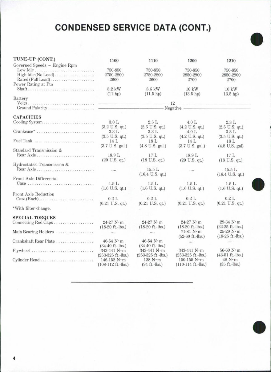
CONDENSED SERVICE DATA 1300 GENERAL Engine Make Engine Model LEK802D Number of Cylinders 2 Bore 80 mm (3.15 in.) Stroke 80 mm (3.15 in.) Displacement 804 cc (49.1 cu. in.) Compression Ratio 23:1 TUNE-UP Firing Order 2-1 Valve Clearance-Cold Intake 0.30 mm (0.012 in.) Exhaust 0.30 mm (0.012 in.) Valve Face Angle Valve Seat Angle Injection Timing, Static-BTDC 23°-24° Injector Opening Pressure 11760 kPa (1705 psi) Governed Speeds-Engine Rpm Low Idle 750-850 High Idle (No Load) 2900-2950 Rated (Full Load) 2700 Power Rating at Pto Shaft 10 kW (13.5 hp) Battery Volts Ground Polarity CAPACITIES Cooling System 4.0 L (4.2 U.S. qt) Crankcase* 4.'^ L (4.5 U.S. qt) Fuel Tank 22 L (5.8 U.S. gal.) Transmission, Rear Axle & Hydraulic System 20 L (21 U.S. qt) . Front Axle Differential Case 1.5 L (1.6 U.S. qt) Front Axle Reduction Case(Each) 0.18 L (0.19 U.S. qt) *With filter change. SPECIAL TORQUES Connecting Rod Caps 25-28 N-m (18-20 ft.-lbs.) Main Bearing Holders Crankshaft Rear Plate 46-54 N-m (34-40 ft.-lbs.) Flywheel 343-441 N-m (253-325 ft.-lbs.) 1310 1500 S753 3 75 mm (2.95 in.) 72 mm (2.83 in.) 954 cc (58.2 cu. in.) 23:1 1-2-3 0.20 mm (0.008 in.) 0.20 mm (0.008 in.) Shibura -45° -45° LET862C 2 85 mm (3.35 in.) 100 mm (3.94 in.) 1134 cc (69.2 cu. in.) 21:1 24 0.30 mm (0.012 in.) 0.30 mm (0.012 in.) 11760kPa (1705 psi) 750-850 2950-3000 2800 12.3 kW (16.5 hp) 11760 kPa (1705 psi) 750-850 2650-2700 2500 12.7 kW (17 hp) 12- Negative 1510 K773 3 77 mm (8.03 in.) 80 mm (3.15 in.) 1117CC (B8.2 cu. in.) 23:1 1-2-3 0.20 mm (0.008 in.) 0.20 mm (0.008 in.) 22° 117H0kPa (1705 psi) 750-850 8000-3050 2800 14.7 kW (19.7 hp) 2.7 L (2.8 U.S. qt) 3.8 L (4.0 U.S. qt) 2f).6 L (7 U.S. gal.) 18 L (19 U.S. qt) 2.4 L (2.5 U.S. qt) 0.22 L (0.23 U.S. qt) 30-34 N-m (22-25 ft.-lbs.) 25-29 N-m (18-22 ft.-lbs.) 27-33 N-m (20-24 ft.-lbs.) 59-69 N-m (44-50 ft-lbs.) 5.3 L (5.6 U.S. qt) 4.3 L (4.5 U.S. qt) 22 L (5.8 U.S. gal.) 20 L (21 U.S. qt) 2.4 L (2.5 U.S. qt) 0.22 L (0.23 U.S. qt) 80-85 N-m (59-63 ft.-lbs.) 46-54 N-m (34-40 ft.-lbs.) 343-441 N-m (253-325 ft.-lbs.) 8.0 L (8.2 U.S. qt) 4.0 L (4.2 U.S. qt) 26.6 L (7 U.S. gal.) 18 L (19 U.S. qt) 2.4 L (2.5 U.S. qt) 0.22 L (0.28 U.S. qt.) 25-27 N-m (18-20 ft-lbs.) 48-53 N-m (36-39 ft.-lbs.) 46-54 N-m (34-40 ft.-lbs.) 59-69 N-m (44-50 ft.-lbs.)
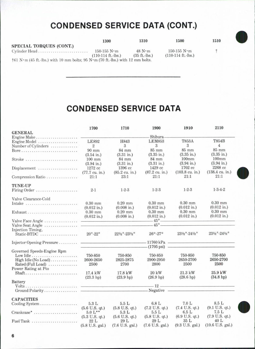
CONDENSED SERVICE DATA (CONT.) 1300 1310 SPECIAL TORQUES (CONT.) Cylinder Head 150-155 N-m 48 N-m (110-114 ft-lbs.) (35 ft-lbs.) t61 N-m (45 ft.-lbs.) with 10 mm bolts; 95 N-m (70 ft.-lbs.) with 12 mm bolts. 1500 1510 150-155 N-m t (110-114 ft-lbs.) CONDENSED SERVICE DATA LE892 2 90 mm (3.54 in.) 100 mm (3.94 in.) 1272 cc (77.7 cu. in.) 21:1 H843 3 84 mm (3.31 in.) 84 mm (3.31 in.) 1396 cc (85.2 cu. in.) 23:1 Shihura LEM853 3 85 mm (3.35 in.) 84 mm (3.31 in.) 1429 cc (87.2 cu. in.) 21:1 T853A 3 85 mm (3.35 in.) 100mm (3.94 in.) 1702 cc (103.8 cu. in.) 21:1 T854B 4 85 mm (3.35 in.) 100mm (3.94 in.) 2268 cc (138.4 cu. in.) 21:1 1700 1710 1900 1910 2110 GENERAL Engine Make Engine Model Number of Cylinders Bore Stroke Displacement Compression Ratio TUNE-UP Firing Order 2-1 1-2-3 1-2-3 1-2-3 1-3-4-2 Valve Clearance-Cold Intake 0.30 mm 0.20 mm 0.30 mm 0.30 mm 0.30 mm (0.012 in.) (0.008 in.) (0.012 in.) (0.012 in.) (0.012 in.) Exhaust 0.30 mm 0.20 mm 0.30 mm 0.30 mm 0.30 mm (0.012 in.) (0.008 in.) (0.012 in.) (0.012 in.) (0.012 in.) Valve Face Angle 45° Valve Seat Angle 45*^ Injection Timing, Static-BTDC 20°-22 Injector Opening Pressure Governed Speeds-Engine Rpm Low Idle 750-850 750-850 750-850 750-850 750-850 High Idle (No Load) 2600-2650 2825-2875 2900-2950 2650-2700 2650-2700 Rated (Full Load) 2500 2700 2800 2500 2500 Power Rating at Pto Shaft 17.4 kW 17.8 kW 20 kW 21.3 kW 25.9 kW (23.3 hp) (23.9 hp) (26.9 hp) (28.6 hp) (34.8 hp) Battery Volts 12 Ground Polarity Negative CAPACITIES CoolingSystem 5.3 L 5.5 L 6.8 L 7.0 L 8.5 L (5.6 U.S. qt) (5.8 U.S. qt) (7.2 U.S. qt) (7.4 U.S. qt) (9.1 U.S. qt) Crankcase* 5.0 L** 5.3 L 5.5 L 6.5 L 7.5 L (5.3 U.S. qt) (5.6 U.S. qt) (5.8 U.S. qt) (6.9 U.S. qt) (7.9 U.S. qt) Fuel Tank 22 L 29 L 29 L 35 L 40 L (5.8 U.S. gal.) (7.6 U.S. gal.) (7.6 U.S. gal.) (9.3 U.S. gal.) (10.6 U.S. gal.) 23V2°-24V2° 11760 kPa -(1705 psi) 23V2°-24V2°
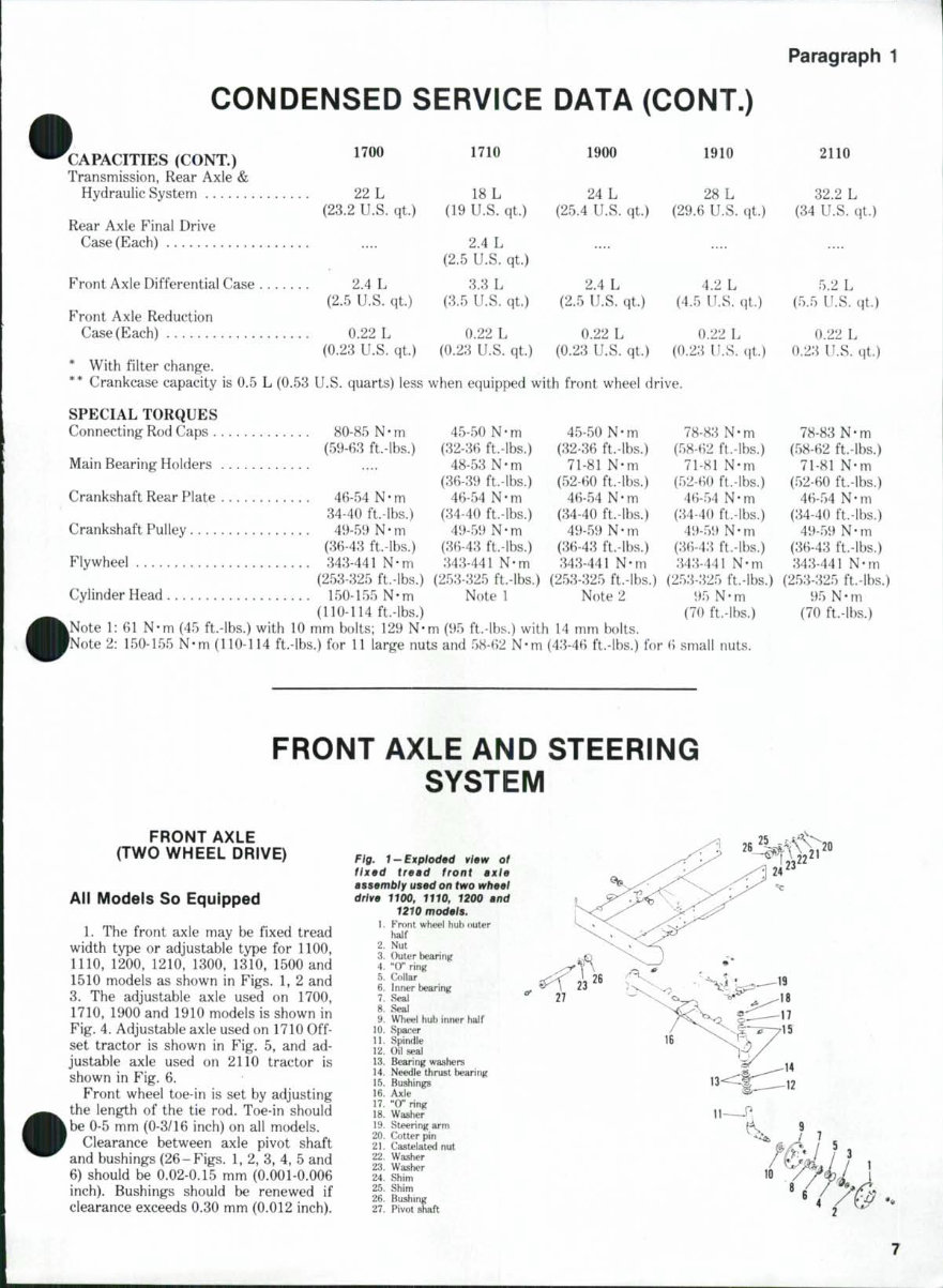
Paragraph 1 CONDENSED SERVICE DATA (CONT.) 'CAPACITIES (CONT.) "00 ^™ ^^^ 191" 2110 Transmission, Rear Axle & Hydraulic System 22 L 18 L 24 L 28 L 32.2 L (23.2 U.S. qt.) (19 U.S. qt.) (25.4 U.S. qt) (29.6 U.S. qt.) (34 U.S. qt.) Rear Axle Final Drive Case (Each) .... 2.4 L (2.5 U.S. qt) Front Axle Differential Case 2.4 L 3.3 L 2.4 L 4.2 L 5.2 L (2.5 U.S. qt) (3.5 U.S. qt.) (2.5 U.S. qt) (4.5 U.S. qt) (5.5 U.S. qt) Front Axle Reduction Case(Each) 0.22 L 0.22 L 0.22 L 0.22 L 0.22 L (0.23 U.S. qt) (0.28 U.S. qt.) (0.23 U.S. qt.) (0.28 U.S. qt) 0.28 U.S. qt.) * With filter change. ** Crankcase capacity is 0.5 L (0.53 U.S. quarts) less when equipped with front wheel drive. SPECIAL TORQUES Connecting Rod Caps 80-85 N • m 45-50 N • m 45-50 N - m 78-88 N - m 78-88 N - m (59-68 ft.-lbs.) (82-36 ft.-lbs.) (32-86 ft.-lbs.) (58-62 ft.-lbs.) (58-62 ft.-lbs.) Main Bearing Holders .... 48-58N-m 71-81 N-m 71-81 N-m 71-81 N-m (86-39 ft.-lbs.) (52-60 ft.-lbs.) (52-60 ft-lbs.) (52-60 ft.-lbs.) Crankshaft Rear Plate 46-54 N-m 46-54 N-m 46-54 N-m 46-54 N-m 46-54 N-m 84-40 ft-lbs.) (34-40 ft.-lbs.) (84-40 ft.-lbs.) (84-40 ft.-tbs.) (84-40 ft.-lbs.) Crankshaft Pulley 49-59 N - m 49-59 N - m 49-59 N - m 49-59 N - m 49-59 N - m (86-48 ft.-lbs.) (86-48 ft.-lbs.) (86-48 ft.-lbs.) (8(>48 ft-lbs.) (86-48 ft.-lbs.) Flywheel 348-441 N-m 848-441 N-m 848-441 N-m 848-441 N-m 848-441 N-m (258-325 ft.-lbs.) (258-825 ft.-lbs.) (258-825 ft-lbs.) (258-825 ft.-lbs.) (258-825 ft-lbs.; Cylinder Head 150-155 N-m Note 1 Note 2 95 N-m 95 N-m • (110-114 ft.-lbs.) (70 ft.-lbs.) (70 ft.-lbs.) Note 1: 61 N-m (45 ft.-lbs.) with 10 mm bolts; 129 N-m (95 ft-lbs.) with 14 mm bolts. Note 2: 150-155 N-m (110-114 ft.-lbs.) for 11 large nuts and 58-62 N-m (48-46 ft.-lbs.) for 6 small nuts. FRONT AXLE AND STEERING SYSTEM FRONT AXLE (TWO WHEEL DRIVE) All Models So Equipped 1. The front axle may be fixed tread width type or adjustable type for 1100, 1110, 1200, 1210, 1300, 1810, 1500 and 1510 models as shown in Figs. 1, 2 and 3. The adjustable axle used on 1700, 1710, 1900 and 1910 models is shown in Fig. 4. Adjustable axle used on 1710 Off- set tractor is shown in Fig. 5, and ad- justable axle used on 2110 tractor is shown in Fig. 6. Front wheel toe-in is set by adjusting the length of the tie rod. Toe-in should be 0-5 mm (0-3/16 inch) on all models. Clearance between axle pivot shaft and bushings (26-Figs. 1, 2, 8, 4, 5 and 6) should be 0.02-0.15 mm (0.001-0.006 inch). Bushings should be renewed if clearance exceeds 0.30 mm (0.012 inch). Fig. 1-exploded view of ftxed tread front axle assembly used on two wheel drtve 1100, 1110, 1200 and 1210 models. 1. Front wheel hub outer half 2. Nut 3. Outer bearinjj 4. "0" ring 5. Collar 6. Inner bearing 7. Seal 8. Seal 9. Wheel hub inner half 10. Spacer U. Spindle 12. Oil seal 13. Bearing washers 14. Needle thrust bearing 15. Bushings 16. Axle 17. "0" ring 18. Washer 19. Steering arm 20. Cotter pin 21. Castelated nut 22. Washer 23. Washer 24. Shim 25. Shim 26. Bushing 27. Pivot shaft
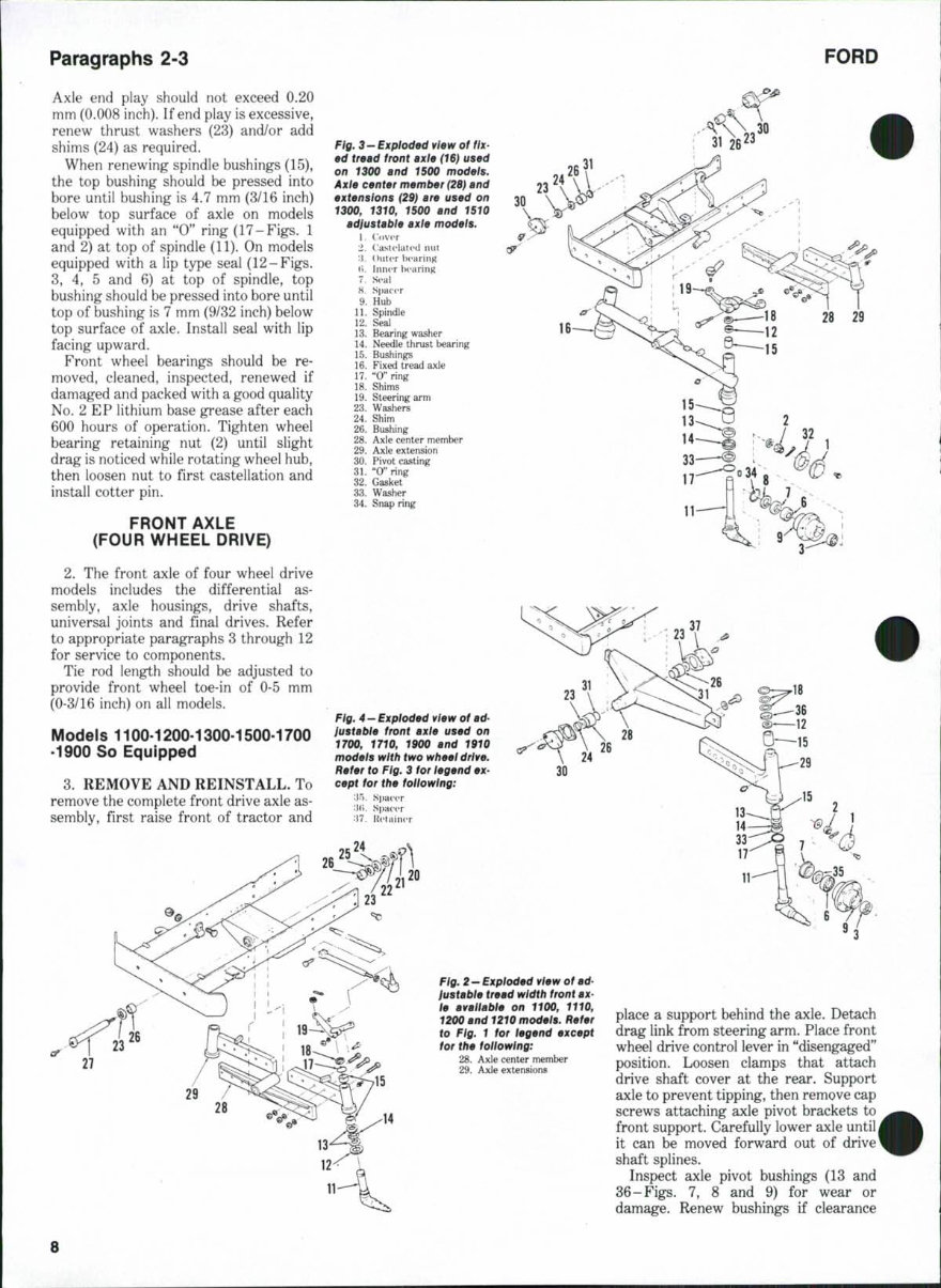
Paragraphs 2-3 FORD Axle end play should not exceed 0.20 mm (0.008 inch). If end play is excessive, renew thrust washers (23) and/or add shims (24) as required. When renewing spindle bushings (15), the top bushing should be pressed into bore until bushing is 4.7 mm (3/16 inch) below top surface of axle on models equipped with an "0" ring (17-Figs, 1 and 2) at top of spindle (11). On models equipped with a lip type seal (12-Figs. 3, 4, 5 and 6) at top of spindle, top bushing should be pressed into bore until top of bushing is 7 mm (9/32 inch) below top surface of axle. Install seal with lip facing upward. Front wheel bearings should be re- moved, cleaned, inspected, renewed if damaged and packed with a good quality No. 2 EP lithium base grease after each 600 hours of operation. Tighten wheel bearing retaining nut (2) until slight drag is noticed while rotating wheel hub, then loosen nut to first castellation and install cotter pin. FRONT AXLE (FOUR WHEEL DRIVE) 2. The front axle of four wheel drive models includes the differential as- sembly, axle housings, drive shafts, universal joints and final drives. Refer to appropriate paragraphs 3 through 12 for service to components. Tie rod length should be adjusted to provide front wheel toe-in of 0-5 mm (0-3/16 inch) on all models. Models 1100-1200-1300-1500-1700 -1900 So Equipped 3. REMOVE AND REINSTALL. To remove the complete front drive axle as- sembly, first raise front of tractor and Fig. 3-Exploded view of fix- ed tread front axle (16) used an 1300 and 1500 models. Axle center member (2S) and extensions (29} are used on 1300, 1310, 1500 and 1510 adiustable axie modeis. 1. Cover 2. llastelatcd nut :i. Outer b(»aring (i. Inner iH'aring 7. Seal 8. Spacer 9. Hub 11. Spindle 12. Seal 13. Bearing washer 14. Needle thrust bearing 15. Bushings 16. Fixed tread axle 17. "0" ring 18. Shims 19. Steering arm 23. Washers 24. Shim 26. Bushing 28. Axle center member 29. Axle extension 30. Pivot casting 31. "0" ring 32. Gasket 33. Washer 34. Snap ring 30 37 18 Ftg. 4 — Expioded view of ad- iustabie front axle used on 1700, 1710, 1900 and 1910 models with two wheei drive. Refer to Fig. 3 for iegend ex- cept for the foiiowing: '•\^y. Spacer '•\i\. Spacer 'M. Retainer Fig. 2-Exploded view of ad- iustabie tread width front ax- le avaliabie on 1100, 1110, 1200 and 1210 models. Refer to Fig. 1 for legend except for the foltowtng: 28. Axle center member 29. Axle extensions place a support behind the axle. Detach drag link from steering arm. Place front wheel drive control lever in "disengaged" position. Loosen clamps that attach drive shaft cover at the rear. Support axle to prevent tipping, then remove cap screws attaching axle pivot brackets to front support. Carefully lower axle until it can be moved forward out of drive shaft splines. Inspect axle pivot bushings (13 and 36-Figs. 7, 8 and 9) for wear or damage. Renew bushings if clearance
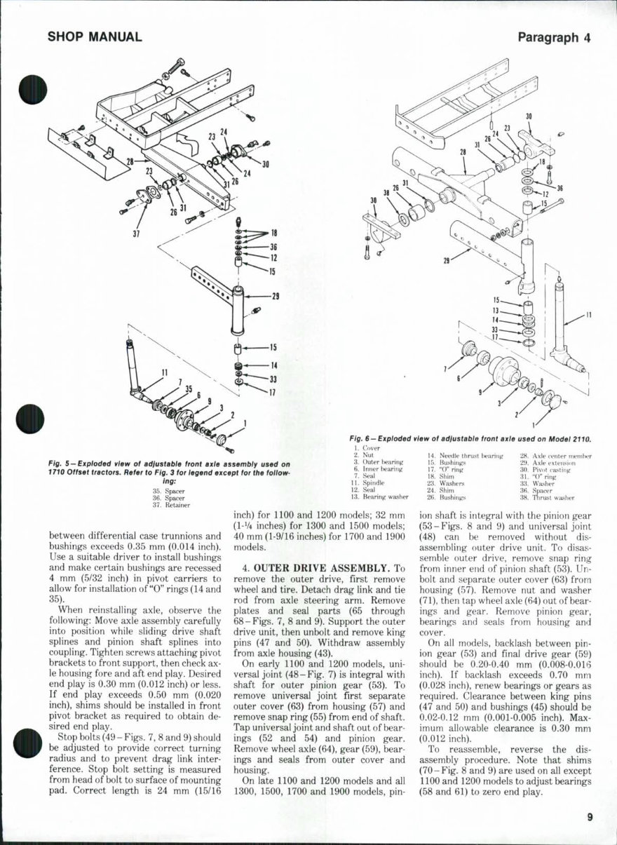
SHOP MANUAL Paragraph 4 Fig. 5 - Exploded view of adiustabie front axie assembiy used on 1710 Offset tractors. Refer to Fig. 3 for iegend except for the follow- ing: 35. Spacer 36. Spacer 37. Retainer inch) for 1100 and 1200 models; 82 mm (I-V4 inches) for 1300 and 1500 models; between differential case trunnions and Fig. 6 —Expioded view of adiustable front axle used on Model 2110. 1. Cover 2. Nut 14. Needle thrust l)earirig 28. Axle tenter ?nemU?r 3. Outer tearing 15. Bushings 21>. Axle extension 6. Injier hearing 17. "0" ring 30. Pivot casting 7. Seal 18. Shim 31. "()" ring 11. Spindle 23. Washers 33. Washer 12. Seal 24. Shim 3fi. Spacer 13. Bearing washer 2H. Bushings 38. Thrust washer bushings exceeds 0.35 mm (0.014 inch). Use a suitable driver to install bushings and make certain bushings are recessed 4 mm (5/32 inch) in pivot carriers to allow for installation of "0" rings (14 and 35). When reinstalling axle, observe the following: Move axle assembly carefully into position while sliding drive shaft splines and pinion shaft splines into coupling. Tighten screws attaching pivot brackets to front support, then check ax- le housing fore and aft end play. Desired end play is 0.30 mm (0.012 inch) or less. If end play exceeds 0.50 mm (0.020 inch), shims should be installed in front pivot bracket as required to obtain de- sired end play. Stop bolts (49 - Figs. 7, 8 and 9) should be adjusted to provide correct turning radius and to prevent drag link inter- ference. Stop bolt setting is measured from head of bolt to surface of mounting pad. Correct length is 24 mm (15/16 40 mm (1-9/16 inches) for 1700 and 1900 models. 4. OUTER DRIVE ASSEMBLY. To remove the outer drive, first remove wheel and tire. Detach drag link and tie rod from axle steering arm. Remove plates and seal parts (65 through 68-Figs. 7, 8 and 9). Support the outer drive unit, then unbolt and remove king pins (47 and 50). Withdraw assembly from axle housing (43). On early 1100 and 1200 models, uni- versal joint (48-Fig. 7) is integral with shaft for outer pinion gear (53). To remove universal joint first separate outer cover (63) from housing (57) and remove snap ring (55) from end of shaft. Tap universal joint and shaft out of bear- ings (52 and 54) and pinion gear. Remove wheel axle (64), gear (59), bear- ings and seals from outer cover and housing. On late 1100 and 1200 models and all 1300, 1500, 1700 and 1900 models, pin- ion shaft is integral with the pinion gear (53-Figs. 8 and 9) and universal joint (48) can be removed without dis- assembling outer drive unit. To disas- semble outer drive, remove snap ring from inner end of pinion shaft (53). Un- bolt and separate outer cover (63) from housing (57). Remove nut and washer (71), then tap wheel axle (64) out of bear- ings and gear. Remove pinion gear, bearings and seals from housing and cover. On all models, backlash between pin- ion gear (53) and final drive gear (59) should be 0.20-0.40 mm (0.008-0.016 inch). If backlash exceeds 0.70 mm (0.028 inch), renew bearings or gears as required. Clearance between king pins (47 and 50) and bushings (45) should be 0,02-0.12 mm (0.001-0.005 inch). Max- imum allowable clearance is 0.30 mm (0.012 inch). To reassemble, reverse the dis- assembly procedure. Note that shims (70-Fig. 8 and 9) are used on all except 1100 and 1200 models to adjust bearings (58 and 61) to zero end play. 9
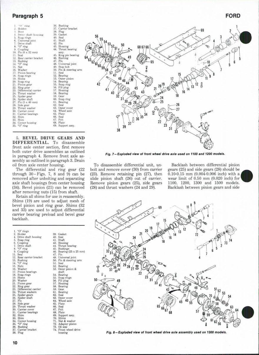
Paragraph 5 FORD 1. "(»• liufi 2 Ilolder l Huol -t. Drive shall housing 5. Snap rings 6. Universal joint 7. Drive shaft 8. "0" ring 9. Coupling 10. Pin (6x32 mm) 11. Seal 12. Rear carrier bracket 13. Bushing 14. "0" ring 15. Nut 16. Washer 17. Pinion bearing 18. Snap rings 19. Shims 20. Snap ring 21. Pinion gear 22. Ring gear 23. Differential carrier 24. Thrust washer 25. Spider gear 26. Spider shaft 27. Pin (5 X 40 mm) 28. Side gear 29. Thrust washer 30. Carrier cover 31. Carrier hearings 32. Shim 33. Shim 34. Center housing 35. "0" ring 36. Bushing 37. Carrier bracket 38. Plug 39. Gasket 40. Seal 41. Shaft 42. Pin 43. Housing 44. Thrust bearing assy. 45. King pin bearing 46. Bushing 1 47. Pin 48. Universal joint 49. Stop bolt 50. Pin & steering arm 51. Seal 52. Bearing 53. Outer pinion 54. Bearing 55. Snap ring 56. Fill plug 57. Housing 58. Bearing 59. Gear 60. Snap ring 61. Bearing 62. Seal 63. Outer cover 64. Wheel axie 65. Plate 66. Seal 67. Felt 68. Plate 69. Support assy. 5. BEVEL DRIVE GEARS AND DIFFERENTIAL. To disassemble front axle center section, first remove both outer drive assemblies as outlined in paragraph 4. Remove front axle as- sembly as outlined in paragraph 3. Drain oil from axle center housing. The differential and ring gear (22 through 30-Figs. 7, 8 and 9) can be removed after unbolting and separating axle shaft housings from center housing (34). Bevel pinion (21) can be removed after removing nuts (15) from shaft. Retain all shims for use in reassembly. Shims (19) are used to adjust mesh of bevel pinion and ring gear. Shims (32 and 33) are used to adjust differential carrier bearing preload and bevel gear backlash. 1. "0" rings 2. Holder 4. Drive shaft housing 5. Snap ring 6. Coupling 7. Drive shaft 8. "0" ring 9. Coupling 11. Seal 12. Rear carrier bracket 13. Bushing 14. "0" ring 15. Nuts 16. Washer 17. Pinion bearings 18. Snap rings 19. Shims 20. Washer 21. Pinion gear 22. Ring gear 23. Differential carrier 24. Thrust washers 25. Spider gears 26. Spider shaft 27. Pin 28. Side gear 29. Thrust washer 30. Carrier cover 31. Carrier bearings 32. Shim 33. Shim 34. Center housing 35. "0" ring 36. Bushing 37. Carrier bracket 38. Plug 39. Gasket 40. Seal 41. Shaft 43. Housing 44. Thrust bearing 45. Bushings 46. Bearing (25 x 25 mm) 47. Pin 48. Universal joint 50. Pin & steering arm 51. Seal 52. Bearing 53. Outer pinion & shaft 54. Bearing 55. Snap rings 56. Fill plug 57. Housing 58. Bearing 59. Gear 61. Bearing 62. Seal 63. Outer cover 64. Wheel axle 65. Plate 66. Seal 67. Felt 68. Plate 69. Support assy. 70. Shims 71. Nut & washer 72. Adapter plates 73. Oil seal 74. Front wheel drive housing Fig. 7-Exploded vtew of front wheei drive axie used on 1100 and 1200 models. To disassemble differential unit, un- bolt and remove cover (30) from carrier (23). Remove retaining pin (27), then slide pinion shaft (26) out of carrier. Remove pinion gears (25), side gears (28) and thrust washers (24 and 29), Backlash between differential pinion gears (25) and side gears (28) should be 0.10-0.15 mm (0.004-0.006 inch) with a wear limit of 0.50 mm (0.020 inch) for 1100, 1200, 1300 and 1500 models. Backlash between pinion gears and side Fig. 8—Expioded vtew of front wheel drive axle assembly used on 1300 models. 10
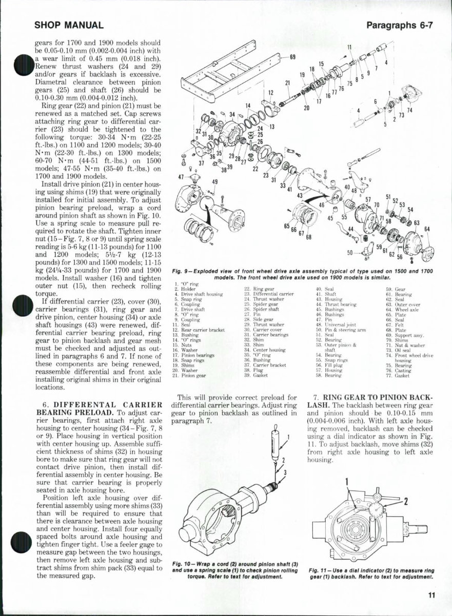
SHOP MANUAL Paragraphs 6-7 gears for 1700 and 1900 models should be 0.05-0.10 mm (0.002-0.004 inch) with a wear limit of 0.45 mm (0.018 inch). 'Renew thrust washers (24 and 29) and/or gears if backlash is excessive. Diametral clearance between pinion gears (25) and shaft (26) should be 0.10-0.30 mm (0.004-0.012 inch). Ring gear (22) and pinion (21) must be renewed as a matched set. Cap screws attaching ring gear to differential car- rier (23) should be tightened to the following torque: 30-34 N-m (22-25 ft.-lbs.) on 1100 and 1200 models; 30-40 N-m (22-30 ft.-lbs.) on 1300 models; 60-70 N-m (44-51 ft.-lbs.) on 1500 models; 47-55 N-m (35-40 ft.-lbs.) on 1700 and 1900 models. Install drive pinion (21) in center hous- ing using shims (19) that were originally installed for initial assembly. To adjust pinion bearing preload, wrap a cord around pinion shaft as shown in Fig. 10. Use a spring scale to measure pull re- quired to rotate the shaft. Tighten inner nut (15-Fig. 7, 8 or 9) until spring scale reading is 5-6 kg (11-13 pounds) for 1100 and 1200 models; 5V2-7 kg (12-13 pounds) for 1300 and 1500 models; 11-15 kg (24V4-33 pounds) for 1700 and 1900 models. Install washer (16) and tighten outer nut (15), then recheck rolling torque. If differential carrier (23), cover (30), carrier bearings (31), ring gear and drive pinion, center housing (34) or axle shaft housings (43) were renewed, dif- ferential carrier bearing preload, ring gear to pinion backlash and gear mesh must be checked and adjusted as out- lined in paragraphs 6 and 7. If none of these components are being renewed, reassemble differential and front axle installing original shims in their original locations. 6. DIFFERENTAL CARRIER BEARING PRELOAD. To adjust car- rier bearings, first attach right axle housing to center housing (34-Fig. 7, 8 or 9). Place housing in vertical position with center housing up. Assemble suffi- cient thickness of shims (32) in housing bore to make sure that ring gear will not contact drive pinion, then install dif- ferential assembly in center housing. Be sure that carrier bearing is properly seated in axle housing bore. Position left axle housing over dif- ferential assembly using more shims (33) than will be required to ensure that there is clearance between axle housing and center housing. Install four equally spaced bolts around axle housing and tighten finger tight. Use a feeler gage to measure gap between the two housings, then remove left axle housing and sub- tract shims from shim pack (33) equal to the measured gap. Fig. 9—Exploded view of front wh99l drtve axle assembly typical of type models. The front wheel drive axle used on 1900 models is 1. "0" rinp 2. Holder 22. Ring gear 4. Drive shaft housing 23. Differential carrier S i 24. Thrust washer 25. Spider gear 26. Spider shaft 27. Pin 28. Side gear 29. Thrust washer 30. Carrier cover 31. Carrier bearings 32. Shinn 33. Shim 34. Center housing 35. "O" ring 36. Bushing 37. Carrier bracket 38. Plug 39. Gasket used on 1500 and 1700 similar. 5. Snap ring 6. Coupling: 7. Drive shaft 8. "0" ring 9. Coupling 11. Seal 12. Rear carrier bracket 13. Bushing 14. "0" rings 15. Nuts 16. Washer 17. Pinion l)earings 18. Snap rings 19. Shims 20. Washer 21. Pinion gear 40. Seal 41. Shaft 43. Housing 44. Thrust hearing 45. Bushings 46. Bushings 47. Pin 48. Universal j(tint 50. Pin & steering arm 51. Seal 52. Bearing 53. Outer pinion & shaft 54. Bearing 55. Snap rings 56. Fill plug 57. Housing 58. Bearing 59. 61. 62. 63. 64. 65. 66. 67. 68. 69. 70. 71. 73. 74. 75. 76. 77. CJear Bearing Seal Outer cover Wheel axle Plate Seal Felt Plate Support assy- Shims Nut & washer Oil seal Front wheel dri\e housing Bearing Casting Gasket This will provide correct preload for differential carrier bearings. Adjust ring gear to pinion backlash as outlined in paragraph 7, 7. RING GEAR TO PINION BACK- LASH. The backlash between ring gear and pinion should be 0.10-0.15 mm (0.004-0.006 inch). With left axle hous- ing removed, backlash can be checked using a dial indicator as shown in Fig. 11. To adjust backlash, move shims (32) from right axle housing to left axle housing. Fig. 10— Wrap a cord (2) around pinion shaft (3) and use a spring scale (1} to check pinion rolling torque. Refer to text for adiustment. Fig. 11 — Use a dial Indicator (2) to measure ring gear (1) backlash. Refer to text for adjustment
This is the complete official full factory service repair manual for the Ford 1100 1110 Tractor. It contains hundreds of pages that allow you to print it out in its entirety or just the pages you need. All styles are covered.
This Ford 1100 1110 Tractor manual is an actual genuine repair service factory manual, not third-party manuals. It will guide you through the fundamentals of maintaining and repairing, step-by-step, to teach you what the factory trained technicians already know by heart. By applying the knowledge in this Ford 1100 1110 Tractor service repair manual, any owner should be able to make the right decisions about what they need to do to maintain and repair the Ford 1100 1110 Tractor.
The manual covers:
Ford 1100 1110 Tractor Engine
Ford 1100 1110 Tractor Lubrication System
Ford 1100 1110 Tractor Cooling System
Ford 1100 1110 Tractor Fuel System
Ford 1100 1110 Tractor Disassembly and Servicing
Ford 1100 1110 Tractor General
Ford 1100 1110 Tractor Separation
Ford 1100 1110 Tractor Clutch
Ford 1100 1110 Tractor Transmission
Ford 1100 1110 Tractor Drive Chain & Sprockets
Ford 1100 1110 Tractor Rear Axle
Ford 1100 1110 Tractor Brakes
Ford 1100 1110 Tractor Front Axle
Ford 1100 1110 Tractor Steering
Ford 1100 1110 Tractor Shocks
Ford 1100 1110 Tractor Body Work
Ford 1100 1110 Tractor Intake & Exhaust
Ford 1100 1110 Tractor Hydraulic System
Ford 1100 1110 Tractor Electrical System
Ford 1100 1110 Tractor Routine Maintenance
Ford 1100 1110 Tractor Advanced Troubleshooting
Ford 1100 1110 Tractor Wiring Diagram
The Ford 1100 1110 Tractor Factory Service Repair Manual contains all necessary illustrations, diagrams, and specifications to guide the mechanic through any repair procedure. It also contains an advanced troubleshooting guide to help diagnose and correct any problem.
This highly detailed Ford 1100 1110 Tractor Factory Service Repair Manual contains everything you will ever need to repair, maintain, rebuild, refurbish, or restore your vehicle. All diagnostic and repair procedures are covered in great detail. This Ford 1100 1110 Tractor Factory Service Repair Manual covers the same information that professional technicians and mechanics have.
You can view and print out the complete repair procedures with this easy to use Ford 1100 1110 Tractor Factory Service Repair Manual - you do not need to be skilled with a computer! Once you have found your information, just print it out and start work. No more messy manuals that you have to keep replacing or can't use anymore due to wear and tear.
Simply print out the pages you need or print the entire manual as a whole!!!
Detailed substeps expand on repair procedure information. Notes, cautions, and warnings throughout each chapter pinpoint critical information. Numbered instructions guide you through every repair procedure step by step. Bold figure numbers help you quickly match illustrations with instructions. Detailed illustrations, drawings, and photos guide you through every procedure. Enlarged inset helps you identify and examine parts in detail. Numbered table of contents is easy to use so that you can find the information you need fast.
This Ford 1100 1110 Tractor service manual also makes it easy to diagnose and repair problems with your machine's electrical system. Troubleshooting and electrical service procedures are combined with detailed wiring diagrams for ease of use.
Ford 1100 1110 Tractor SERVICE MANUAL!!
PRODUCT DETAILS:
File Format: .PDF or .OVA
Language: English
Printable: without any restriction
Delivery: link will appear on the checkout page after payment is complete
Requirements: Adobe Reader
Complete comes in format which can work under all PC based windows operating system and Mac also. It saves to your hard-drive and can be burned to CD-ROM. All pages are printable. No need to pay for shipping and wait for the overpriced paper textbook or CD-ROM to arrive via snail mail.
Save $50 - $60 per hour on shop labor costs. You will be able to do all of the servicing yourself with this Ford 1100 1110 Tractor Factory service manual. This high-resolution able manual is fully printable, you can print 1 page, 1 chapter, or the whole thing. A wealth of indispensable information for any serious owner. View and print any page or diagram that you want.
You can easily find what you need using the search function and then print out only the pages you need. This is the Ford 1100 1110 Tractor service manual you have been waiting for. Incredibly detailed, step-by-step instructions and photos to guide you through all service, maintenance, repairs, and tuning.
Recently Viewed
5,521,897Happy Clients
2,594,462eManuals
1,120,453Trusted Sellers
15Years in Business
Price:
Actual Price:
Ford 1100 1110 Tractor Factory Service Repair Manual