




introduction
This publication is intended for the trained technician who must operate on our tractors.
It contains all general information relating to our tractor range, and in particular it highlights the inspection, overhauling
and adjustment procedures as well as the main instructions for dismantling and reassembling operations.
The workshop manual is a natural summary for the mechanic who has attended the vocational training and specializa-
tion courses, which are held every year at our Service School, to permit him to perform a precise and qualified work on
tractor.
Its contents are therefore an exhaustive reference book for the experienced mechanic who desires to refresh his me-
mory on the sequence of the operations to be done. It is then good practice for every authorized dealer mechanic to
have at his disposal this publication, so that it may be consulted quickly when necessary.
We wish to thank in advance for the cooperation all thos people, who will let us have their suggestions in order to make
this publication more complete.
1
WORKSHOP MANUAL

List of contents
Tractor configurations AGROPLUS 60 - 70 - 80 ......................................................................................................6
Dimensions and weights...........................................................................................................................................7
Prescribed lubricants and capacities ........................................................................................................................8
Conversion tables .....................................................................................................................................................9
Parts .......................................................................................................................................................................10
1 - ENGINE
................................................................................................................................................................................ 11
2 - CLUTCH
Gearshift clutch.......................................................................................................................................................12
General specifications ............................................................................................................................................ 12
Cecking clutch ........................................................................................................................................................ 16
Adjusting clutch control pedal .................................................................................................................................16
Bleeding air from the hydraulic circuit .....................................................................................................................16
Stripping the slave cylinder .....................................................................................................................................17
Stripping the master cylinder ..................................................................................................................................18
Diagnosing malfunctions ........................................................................................................................................ 20
POWERSHIFT unit, general specifications ............................................................................................................21
POWERSHIFT unit detach from the gear box ........................................................................................................24
Assembly of POWERSHIFT unit ...........................................................................................................................35
Re-assembly of the POWERSHIFT unit. ...............................................................................................................37
Fitting the oil manifolds of the POWERSHIFT unit ................................................................................................39
Diagnosing malfunctions ........................................................................................................................................ 44
3 - TRANSMISSION
General specifications ............................................................................................................................................ 45
Technical specifications .......................................................................................................................................... 45
Speed change configurations .................................................................................................................................47
Section through transmission .................................................................................................................................51
Section through transmission with POWERSHIFT unit ..........................................................................................52
Separating the front gearbox from the engine ........................................................................................................61
Dismantling the gearbox .........................................................................................................................................62
Removal of the gearbox input and P.T.O. shafts ....................................................................................................62
Separating the POWERSHIFT unit from the gearbox ........................................................................................... 62
Removal of the gear train positioned in the front gearbox ......................................................................................63
Disassembly of the inversor control rods and forks ................................................................................................64
Dismantling of the gearchange rod and fork assembly ..........................................................................................65
Dismantling of the gearchange selector rods and forks assembly ......................................................................... 66
Removal of the shaft with the actuator for engagement/disengagement of the front-wheel drive ..........................67
Removal of the range gear shaft ........................................................................................................................... 67
Examining parts removed .......................................................................................................................................68
Adjusting play of the gearbox shafts by means of the thrust plates on the mini/inversor
shaft and the secondary shaft ...............................................................................................................................69
Warnigns related to assembly of the gears of the P.T.O. unit, the range reduction unit and synchronised
P.T.O. shaft ............................................................................................................................................................ 73
Assembly of the P.T.O. .......................................................................................................................................... 73
Installation of the range reduction unit, the gear for the front-wheel drive shaft
and the parking brake discs...................................................................................................................................73
Points where sealant is to be used .........................................................................................................................75
Tightening torques .................................................................................................................................................. 78
Bevel drive adjustment ...........................................................................................................................................81
Servicing operations ...............................................................................................................................................82
Rear power take-off ................................................................................................................................................ 83
P.T.O. clutch ...........................................................................................................................................................88
Technical specifications .......................................................................................................................................... 89
Correct positions of P.T.O. sensors and cables ..................................................................................................... 89
Clutch inspection .................................................................................................................................................... 91
Checking clutch hydraulic pressures ......................................................................................................................92
Checking the end-play of the front shaft of the P.T.O. clutch ................................................................................. 93
Renewal of the rear P.T.O. clutch ..........................................................................................................................94
Main operations for removal of the rear P.T.O. unit ............................................................................................... 95
Diagnosing malfunctions ...................................................................................................................................... 100
2

4 - AXLES
Rear axle .............................................................................................................................................................. 101
Installing the rear half-shafts ...............................................................................................................................102
Removal and disassembly of the epicyclic reduction unit ......................................................................................... 104
Fitting lateral stub axles of the wheel ...................................................................................................................105
2WD extendible axle.............................................................................................................................................106
Removing the axle from the front support ............................................................................................................ 108
Centre steering lever ............................................................................................................................................ 111
Wheel hub ............................................................................................................................................................ 112
End float adjustment .............................................................................................................................................114
Front-wheel drive.................................................................................................................................................. 115
Specifications .......................................................................................................................................................115
Epicyclic reduction unit .........................................................................................................................................119
Side hubs.............................................................................................................................................................. 121
Tightening torques................................................................................................................................................ 122
Adjusting bevel gears ...........................................................................................................................................124
Adjustment of the internal control of the mechanical differential lock ................................................................... 125
Installing the differential assembly into the drive axle .......................................................................................... 125
Diagnosing malfunctions ...................................................................................................................................... 126
5 - VEHICLE
Brakes - General information................................................................................................................................ 127
Hydraulic pump.....................................................................................................................................................128
Assembly of brake master cylinder ...................................................................................................................... 130
Checking the front brake disks on 2WD and 4WD front axles and the rear brake disks ...................................... 131
Adjusting service brake pedals .............................................................................................................................131
Correct installation of inspection cover for parking brake discs............................................................................ 132
Checking parking brake pads ...............................................................................................................................134
Bleeding air from the brake hydraulic system....................................................................................................... 135
“Separate Brakes” valve .......................................................................................................................................136
Diagnosing malfunctions ...................................................................................................................................... 140
Hydraulic lift with “load sensing” ...........................................................................................................................141
Installing the lift and front cover plate of the gearbox ........................................................................................... 142
Lift mechanism .....................................................................................................................................................142
Checking the safety valves ...................................................................................................................................142
Checking the protrusion of the non-return valve................................................................................................... 143
Adjusting the lift .................................................................................................................................................... 145
Lift hydraulic circuit ...............................................................................................................................................147
Sensing arm assemblyMontaggio dell'organo sensibile ....................................................................................... 154
Power-lift distributor valve spring setting specifications ....................................................................................... 155
Electronic lift .........................................................................................................................................................156
Control panel ........................................................................................................................................................ 157
Control level or depth control knob .......................................................................................................................157
Mix position/draft control .......................................................................................................................................157
Lowering speed control knob................................................................................................................................ 158
Maximum lift height control knob .......................................................................................................................... 158
Up/Down control switch ........................................................................................................................................ 158
Up control .............................................................................................................................................................158
Control/Float mode ...............................................................................................................................................158
Lift status indicator light ........................................................................................................................................ 158
Remote pushbuttons for lift operation from ground .............................................................................................. 159
Lift operation .........................................................................................................................................................160
List of electronic lift tests ...................................................................................................................................... 164
Precautions for electronic equipment ...................................................................................................................173
Checking the electronics system .......................................................................................................................... 173
Checking mechanical components .......................................................................................................................173
Front hydraulic liftSollevatore idraulico anteriore.................................................................................................. 174
Hydraulic accumulator and antishock valve for front lift ....................................................................................... 176
Front power take-off - General information........................................................................................................... 177
Section of the P.T.O. ............................................................................................................................................ 178
Fitting the "RING-FEEDER" rings .........................................................................................................................182
Checking the clutch .............................................................................................................................................. 183
Diagnosing malfuntions ........................................................................................................................................ 184
Spring specifications.............................................................................................................................................184
3

6 - CONTROLS
Hydrostatic steering .............................................................................................................................................. 185
Inspections and checks ........................................................................................................................................ 186
Steering pump ...................................................................................................................................................... 186
Directional control valve .......................................................................................................................................186
Check the setting of the pressure relief valve....................................................................................................... 186
Bleeding the hydraulic circuit ................................................................................................................................186
Assembly of orbital pump unit ..............................................................................................................................186
Teering wheel shaft and steering cylinders ......................................................................................................... 187
Instructions for the hydrostatic steering distributor assembly ............................................................................... 189
Diagnosing malfuntions ........................................................................................................................................ 192
Mechanical controls .............................................................................................................................................. 196
Electro-hydraulic controls .....................................................................................................................................197
Front P.T.O. clutch engagement control ...............................................................................................................202
Rear P.T.O. clutch engagement control ...............................................................................................................202
Differential lock engagement control ....................................................................................................................202
Front-wheel drive engagement control .................................................................................................................202
Rear P.T.O. engagement control ..........................................................................................................................202
Gearbox ................................................................................................................................................................ 202
Front and rear lift .................................................................................................................................................. 202
Hydraulic circuit diagram ...................................................................................................................................... 202
Solenoid valve - Specifications .............................................................................................................................207
Adjustment of front and rear differential lock control ............................................................................................214
7 - BODYWORK
Platform ................................................................................................................................................................ 215
Cab - General information .................................................................................................................................... 216
Cab air filter .......................................................................................................................................................... 218
Screen wash .........................................................................................................................................................218
Screen wipers (front and rear) ..............................................................................................................................218
Removing the driving platform complete with cab ................................................................................................219
Breakage of the top hood release cable ...............................................................................................................220
High visibility cab roof ...........................................................................................................................................222
8 - SYSTEMS
Ventilation .............................................................................................................................................................223
Heating System .................................................................................................................................................... 223
Air conditioning unit for cabs ................................................................................................................................227
Operation and maintenance of the air-conditioning system ................................................................................. 228
Water dripping from the points at which condensate drain lines are connected to the conditioning unit ............229
Checking system .................................................................................................................................................. 231
System safety elements .......................................................................................................................................231
Temperature regulation ........................................................................................................................................ 231
Charging the system.............................................................................................................................................232
Filling the metering unit ........................................................................................................................................ 232
Refilling the system with oil ..................................................................................................................................232
Verifying operation of the system after recharging ............................................................................................... 234
Directions for tightening air conditioning system pipeline fittings ......................................................................... 234
Diagnosing malfuntions ........................................................................................................................................ 241
Hydraulic system .................................................................................................................................................. 242
Oil filters ................................................................................................................................................................ 243
Hydraulic pumps ...................................................................................................................................................243
Checking the relief valves of the hydraulic lift system ..........................................................................................243
Stripping the hydraulic pump ................................................................................................................................244
Auxiliary hydraulic spool valves ............................................................................................................................247
Checking the pressure relief valve setting ............................................................................................................250
Checking the operating pressure ..........................................................................................................................250
Conversion of auxiliary spool valves from double acting to single acting operation ............................................. 250
Checking the surface of the valve spools .............................................................................................................250
Trailer hydraulic braking system ...........................................................................................................................251
Use of the tractor with CUNA 341/01 hydraulic trailer braking ............................................................................. 253
Installing the hydraulic braking valve for trailers equipped with “safety brake”
( ITALIAN version) ................................................................................................................................................ 258
Electrical system AGROPLUS 60 (up serial number1017) - 70 (up serial number 2773) - 80 ............................. 261
Electrical system AGROPLUS 60 (under serial number 1016) - 70 (under serial number 2772) ........................445
4

General safety directions...................................................................................................................................... 446
Jump start utilizing another battery.......................................................................................................................447
Recharge system.................................................................................................................................................. 449
Heating system .....................................................................................................................................................450
Starting system .....................................................................................................................................................450
Ignition key ...........................................................................................................................................................452
Ventilation control .................................................................................................................................................452
Push button control ...............................................................................................................................................452
Beacon push button.............................................................................................................................................. 454
Work ligths............................................................................................................................................................ 454
2-Speed windscreen wiper switch ........................................................................................................................ 454
Relay .................................................................................................................................................................... 455
Electronic flasher unit ...........................................................................................................................................455
Switch controlling.................................................................................................................................................. 456
Switch controlling: differential lock - P.T.O. clutch - 4RM - 540 1000 rpm/min P.T.O. speed selector -
Economy P.T.O. - Live P.t.o. - electric starter system......................................................................................... 456
Switch for emergency brake .................................................................................................................................456
Fuse box ...............................................................................................................................................................457
Instrument panel with digital display .....................................................................................................................458
Operation of the broken belts alarm control unit ................................................................................................... 460
Engine stop operation with a type 2MH engine control unit ................................................................................. 462
Electrical wiring.....................................................................................................................................................465
9 - APPENDIX
Power lift tester version 1.24a ...................................................................................................................................I
5

TRACTOR CONFIGURATIONS:
CAB
- ventilation
- ventilation + heating
- ventilation + heating + air conditioning
GEARBOX
Fully synchronised:
20 Forward + 10 Reverse: 5 speeds x 2 ranges (Hair-Tortoise)
+ SYNCHROSPLIT (H/fast-L/slow-R/rearward)
30 Forward + 15 Reverse: 5 speeds x 3 ranges (Hair-Tortoise-Snail)
+ SYNCHROSPLIT (H/fast-L/slow-R/rearward)
45 Forward + 45 Reverse: 5 speeds x 3 ranges (Hair-Tortoise-Snail)
+ shuttle + version POWERSHIFT - -
CONTROLS
- rear P.T.O. clutch with electro-hydraulic control
- 4WD with mechanical control or optional electro-hydraulic control
- electronic engine throttle
MECHANICALLY OPERATED REAR POWER-LIFT
- with supplementary rams
- without supplementary rams
MAIN EQUIPMENT
- front P.T.O.
- front lift
- hydraulic pump capacities increased by 27 l/min (for hydrostatic steering, electro-hydraulic control
unit and gearbox lubrication) and by 47 l/min (for trailer braking, auxiliary control valves and lift).
- hydraulic trailer braking
- 4-way or 6-way control valves with “Flow Divider”
- etc.
6
AGROPLUS 60 - 70 - 80 2RM WITH PLATFORM
2RM WITH CAB
4RM WITH PLATFORM
4RM WITH CAB
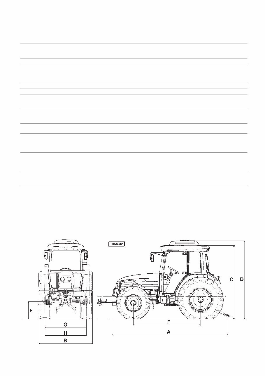
DIMENSIONS AND WEIGHTS
AGROPLUS 60 AGROPLUS 70 -80
2 WD 4 WD 2 WD 4 WD
Length max:
- without linkage (A) mm 3800 3835 3930 3985
- with front and rear linkage (A) mm - 4350 - 4480
Width min./max. (B) mm 1920 -2320 1920-2320 1920-2320 1920-2320
Height:
- al telai di sicurezza (C) mm 2420 2420 1490
- at cab (standard) (C) mm 2430 2430 1700
- at cab (with air conditioning) (D) mm 2595 2595 2360
Ground clearance (E) mm 345 345 365 365
Wheel base (F) mm 2162 2112 2292 2242
Front track
base (G) mm 1400 1440 1400 1440
min./max. 1300-1600 1340-1740 1300-1600 1340-1740
Rear track
base (H) mm 1500 1500 1500 1500
min./max. 1400-1900 1400-1900 1400-1900 1400-1900
Min. turning radius
without brakes (mm) 3500 4050 3700 4300
Operating weight
(without front lift)
- with plataform kg 2355 2705 2555 2905
- with cab kg 2550 2900 2750 3100
Max. permissible load
- front kg 240 240 240 240
- rear kg 200 200 200 200
- block kg - 250 - 250
Tyres
- front 7.50-16 12.4R 20 7.50-16 11.2R 24
- rear 14.9R30 14.9R30 16.9R30 16.9R30
7
PRESCRIBED LUBRICANTS AND FUELS
8
PRESCRIBED LUBRICANTS AND FUELS AGROPLUS 60/70/80
Part to be supplied
Litres
(US gal)
Produc
t
Specificati
ons
SDFG
change
hours
Engine AGROPLUS 60
9.5**
(2.5)
Engine AGROPLUS 70/80
11**
(2.9)
AKROS TURBO
15W40
Sae 15w40
ACEA E3-96
API CF
SDFG OM-1991
MIL-L-2104 E level
MB 228.3 level
500*
Gearbox and rear axle
41
(10.8)
AKROS MULTI
Sae 10w30
Sae 20w30
UTTO API GL4
SDFG OT-1891
1200
Central axle
6 (6.3)
Side reductions
1.5x2
(1.6x2)
Front PTO
2.5 (2.6)
AKROS MULTI
Sae 10w30
Sae 20w30
UTTO API GL4
SDFG OT-1891
1200
Brakes and clutch control
MAX
AKROS MATIC
ATF DEXRON II D
SDFG OF-1691
Lubrification points
AKROS GREASE T2
NLGI 2 - LITIO
SDFG GR-1202 L
50
(*)1
°
replace after 50 hours
(**) With filter + 1.5 litre
s

CONVERSION TABLE FROM
FROM TO multiply by:
inch cm 2.540
cm inch 0.394
foot m 0.305
m foot 3.281
yard m 0.914
m yard 1.094
Eng. miles km 1.609
km Eng. miles 0.622
Sq.in. cm2 6.452
cm2 Sq.ft. 0.155
Sq.ft. m2 0.093
m2 Sq.ft. 10.77
Sq.yard m2 0.835
m2 Sq.yard 1.197
Cu.in. cm3 16.39
cm3 Cu.in. 0.061
Cu.ft. Liter 28.36
Liter Cu.ft. 0.035
Cu.yard m3 0.763
m3 Cu.yard 1.311
Imp.gall. Liter 4.547
Liter Imp.gall. 0.220
US gall. Liter 3.785
Liter US gall. 0.264
pint Liter 0.568
Liter pint 1.762
quart Liter 1.137
Liter quart 0.880
oz. kg 0.028
kg oz. 35.25
lb. kg 0.454
kg lb. 2.203
lb.ft. kgm 0.139
kgm lb.ft. 7.233
lb/in. kg/m 17.87
kg/m lb/in. 0.056
lb./sq.in. kg/cm2 0.070
kg/cm2 lb/sq.in. 14.22
lb./Imp.gall. kg/l 0.100
kg/l lb./Imp.gall. 10.00
lb./US gall. kg/l 0.120
kg/l lb./US gall. 8.333
lb./cu.ft. kg/m3 16.21
kg/m3 lb./cu.ft. 0.062
cu.ft./lb. m3/kg 0.062
m3/kg cu.ft./lb. 16.21
Nm kgm 0.102
kgm Nm 9.81
kW PS 1.36
PS kW 0.736
bar kg/cm2 1.014
kg/cm2 bar 0.981
dm3 l 1
l dm3 1
9
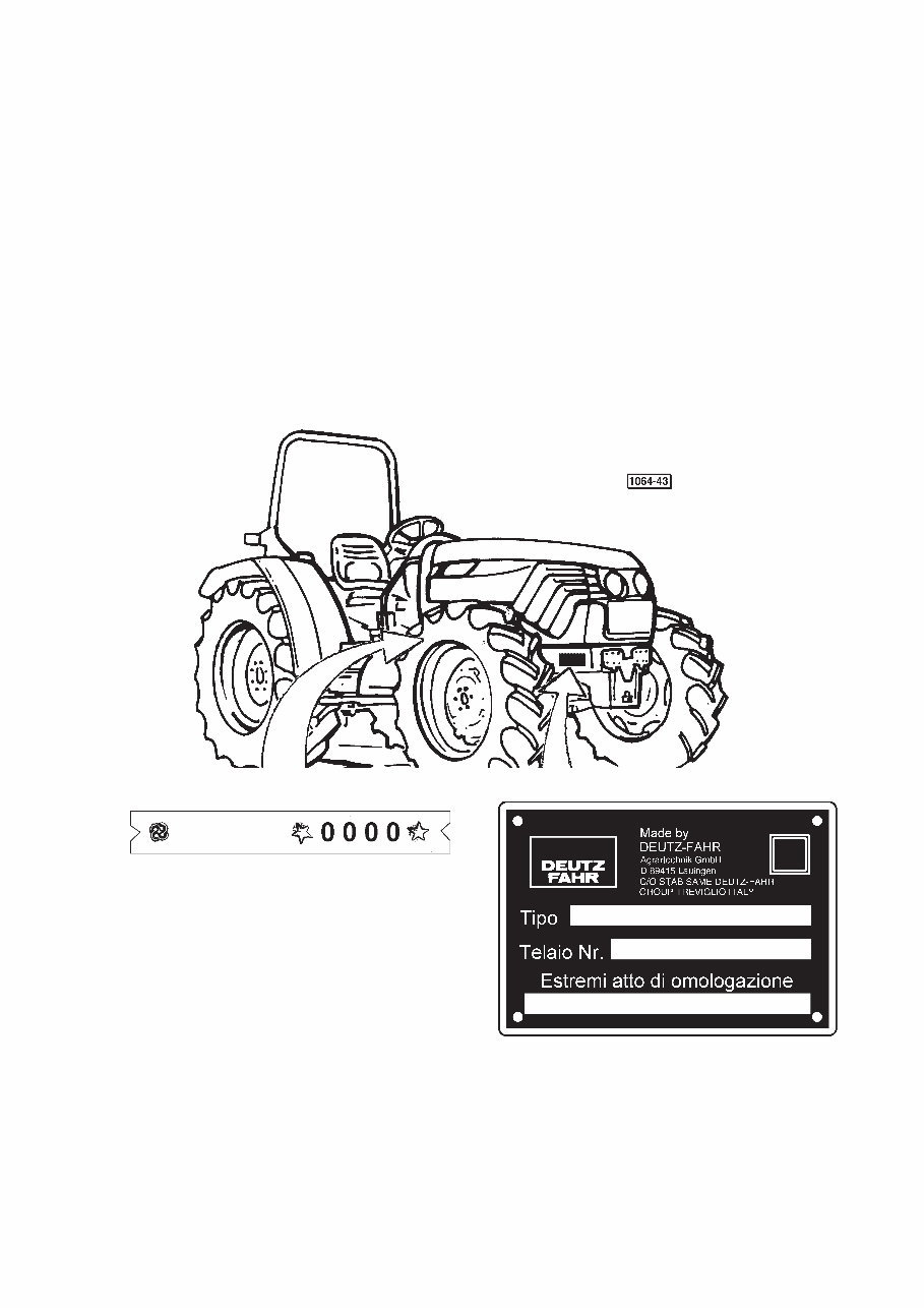
HOW TO ORDER SPARE PARTS
To ensure perfect tractor efficiency thus avoiding serious drawbacks, and to optimize your investment and the operatio-
nal expenses, the use of “ORIGINAL SPARE PARTS” is recommended.
Spare parts orders must specify the following:
Tractor serial number and engine serial number (if the engine is concerned).
Spare part name and reference code.
ENGINE TYPE AND TRACTOR FRAME TYPE
SERIAL NUMBER AND SERIAL NUMBER
10
You're Reading a Preview
What's Included?
 Lifetime Access
Fast Download Speeds
Online & Offline Access
Access PDF Contents & Bookmarks
Full Search Facility
Print one or all pages of your manual
$41.99
DEUTZ FAHR Tractor AGROPLUS 60 70 80 FACTORY Workshop Manual
Viewed 48 Times Today

What's Included?
Lifetime Access
Fast Download Speeds
Online & Offline Access
Access PDF Contents & Bookmarks
Full Search Facility
Print one or all pages of your manual
$41.99

Secure transaction
What's Included?
Lifetime Access
Fast Download Speeds
Online & Offline Access
Access PDF Contents & Bookmarks
Full Search Facility
Print one or all pages of your manual
Description
The DEUTZ FAHR TRACTOR AGROPLUS FACTORY WORKSHOP SERVICE MANUAL covers the AGROPLUS 60 70 80 models. This manual is designed for both professional mechanics and DIY enthusiasts. It provides comprehensive technical information for repair and maintenance tasks. The manual is available in .PDF format, allowing for easy access and use. With this manual, users can perform repairs and service tasks with confidence, saving time and money.


