introduction This publication is intended for the trained technician who must operate on our tractors. It contains all general information relating to our tractor range, and in particular it highlights the inspection, overhauling and adjustment procedures as well as the main instructions for dismantling and reassembling operations. The workshop manual is a natural summary for the mechanic who has attended the vocational training and specializa- tion courses, which are held every year at our Service School, to permit him to perform a precise and qualified work on tractor. Its contents are therefore an exhaustive reference book for the experienced mechanic who desires to refresh his me- mory on the sequence of the operations to be done. It is then good practice for every authorized dealer mechanic to have at his disposal this publication, so that it may be consulted quickly when necessary. We wish to thank in advance for the cooperation all thos people, who will let us have their suggestions in order to make this publication more complete. 1 WORKSHOP MANUAL
LIST OF CONTENTS Tractor configurations AGROCOMPACT ................................................................................................................. 6 Dimensions and weights...........................................................................................................................................7 Prescribed lubricants and capacities ......................................................................................................................10 Conversion tables ...................................................................................................................................................11 Parts .......................................................................................................................................................................12 1 - ENGINE Engine section ........................................................................................................................................................ 13 General characteristics ...........................................................................................................................................20 Timing specifications ..............................................................................................................................................21 Lubrication system - specifications .........................................................................................................................22 Fuel supply system - specifications ........................................................................................................................23 Turbocharger - specifications .................................................................................................................................24 Cooling system .......................................................................................................................................................25 Engine cylinder block ..............................................................................................................................................26 Installing bushings into the camshaft journals ........................................................................................................26 Adjusting backlash between the gear teeth of the auxiliary engine drive ............................................................... 27 Support for hydraulic pumps or air compressor located between engine block and timing cover ..........................27 Timing idler gea ...................................................................................................................................................... 29 Cylinders.................................................................................................................................................................30 Main bearings .........................................................................................................................................................33 Crankshaft .............................................................................................................................................................. 35 Connecting rods - connecting rod bearings and bushings ..................................................................................... 38 Pistons .................................................................................................................................................................... 39 Piston rings .............................................................................................................................................................39 Counterweights for 4-cylinder engines ................................................................................................................... 44 Engine flywheel ...................................................................................................................................................... 45 Checking camshaft .................................................................................................................................................48 Checking camshaft bushings ..................................................................................................................................48 Checking timing gear ..............................................................................................................................................48 Cylinder heads - valves - valve rockers ..................................................................................................................49 Cleaning cylinder heads .........................................................................................................................................50 Checking engine compression ...............................................................................................................................53 Oil pump ................................................................................................................................................................ 54 Checking pressure relief valve ...............................................................................................................................54 Fitting shims between engine oil pan and front support ......................................................................................... 55 Fuel injection nozzles .............................................................................................................................................56 Mechanical-type engine governor ......................................................................................................................58 Mounting governor weights ...................................................................................................................................59 Calibrating engine governor ...................................................................................................................................61 Engine governor control assembly .........................................................................................................................64 Installing and checking the pick-up.........................................................................................................................68 Installing and checking actuator .............................................................................................................................69 Fuel injection pumps...............................................................................................................................................76 Injection pump control system ................................................................................................................................76 Installing injection pump control bar guide supports ..............................................................................................77 Engine timing .......................................................................................................................................................... 77 Positioning the pumps ............................................................................................................................................80 Fuel prefilter ............................................................................................................................................................ 83 Fuel filter .................................................................................................................................................................83 Draining water from fuel filter ..................................................................................................................................83 Fan assembly .........................................................................................................................................................85 Turbocharging 70F3 - F90 ....................................................................................................................................88 Engine air filter ........................................................................................................................................................ 92 Tightening torques .................................................................................................................................................. 92 Instructions for engine assembly ............................................................................................................................94 Diagnosing malfunctions ......................................................................................................................................108 2
2 - CLUTCH Gearshift clutch.....................................................................................................................................................110 Spring specifications to Belleville washer for the clutch engagement .................................................................. 110 Cecking clutch ...................................................................................................................................................... 114 Adjusting clutch control pedal ...............................................................................................................................114 Bleeding air from the hydraulic circuit ................................................................................................................... 114 Stripping the slave cylinder ...................................................................................................................................115 Stripping the master cylinder ................................................................................................................................ 116 Diagnosing malfunctions ...................................................................................................................................... 118 Powershift unit ...................................................................................................................................................... 119 Powershift unit detach from the gear box ............................................................................................................. 122 Assembly of Powershift unit .................................................................................................................................133 Re-assembly of the Powershift unit. ..................................................................................................................... 135 Fitting the oil manifolds of the Powershift unit ...................................................................................................... 138 Diagnosing malfunctions ...................................................................................................................................... 142 3 - TRANSMISSION General specifications .......................................................................................................................................... 143 Technical specifications........................................................................................................................................ 143 Speed change configurations ...............................................................................................................................144 Longitudinal section through transmission ........................................................................................................... 149 Longitudinal section through transmission with Powershift unit ........................................................................... 150 Rear axle longitudinal section...............................................................................................................................151 Views of the gearbox. ...........................................................................................................................................154 Views of the gearbox with hydraulic shuttle.......................................................................................................... 156 Range selector rods and forks..............................................................................................................................159 Hydraulic shuttle control .......................................................................................................................................160 Removal and refitting............................................................................................................................................ 161 Removal of the rear gearbox without removing the platform (tractors equipped with platform or cab only).........161 Separating the front gearbox from the engine ...................................................................................................... 162 Dismantling the gearbox .......................................................................................................................................162 Removal of the gearbox input and P.T.O. shafts.................................................................................................. 162 Separating the Powershift unit from the gearbox ................................................................................................ 162 Removal of the gear train positioned in the front gearbox.................................................................................... 163 Disassembly of the inversor control rods and forks.............................................................................................. 164 Dismantling of the gearchange rod and fork assembly. ....................................................................................... 165 Dismantling of the gearchange selector rods and forks assembly ....................................................................... 166 Removal of the shaft with the actuator for engagement/disengagement of the front-wheel drive........................ 167 Removal of the range gear shaft ......................................................................................................................... 167 Examining parts removed .....................................................................................................................................168 Gearbox case .......................................................................................................................................................168 Shafts ...................................................................................................................................................................168 Gears.................................................................................................................................................................... 168 Synchronizers .......................................................................................................................................................168 Bearings ...............................................................................................................................................................168 Adjusting play of the gearbox shafts by means of the thrust plates on the mini/inversor shaft and the secondary shaft ........................................................................................................ 169 Warnigns related to assembly of the gears of the P.T.O. unit, the range reduction unit and synchronised P.T.O. shaft ............................................................................................................................ 173 Assembly of the P.T.O......................................................................................................................................... 173 Installation of the range reduction unit, the gear for the front-wheel drive shaft and the parking brake discs ......173 Points where sealant is to be used .......................................................................................................................177 Bevel drive adjustment .........................................................................................................................................183 Servicing operations .............................................................................................................................................184 Tightening torques................................................................................................................................................ 184 Rear power take-off .............................................................................................................................................. 185 P.T.O. clutch .........................................................................................................................................................192 Technical specifications........................................................................................................................................ 193 Correct positions of P.T.O. sensors and cables ................................................................................................... 193 Clutch inspection .................................................................................................................................................. 195 Checking clutch hydraulic pressures .................................................................................................................... 196 Checking the end-play of the front shaft of the P.T.O. clutch ............................................................................... 197 Renewal of the rear P.T.O. clutch ........................................................................................................................ 198 Main operations for removal of the rear P.T.O. unit ............................................................................................. 199 Ooperations for removal of the rear P.T.O. unit ................................................................................................... 200 Diagnosing malfunctions ...................................................................................................................................... 204 3
4 - AXLES Rear axle .............................................................................................................................................................. 205 Installing the rear half-shafts ...............................................................................................................................205 Removal and disassembly of the epicyclic reduction unit ......................................................................................... 208 Fitting lateral stub axles of the wheel ................................................................................................................... 209 2WD extendible axle.............................................................................................................................................210 Removing the axle from the front support ............................................................................................................212 Wheel hub ............................................................................................................................................................ 214 Front-wheel drive .................................................................................................................................................. 217 Removal of the axle from the front carrier ............................................................................................................218 Epicyclic reduction unit .........................................................................................................................................221 Side hubs .............................................................................................................................................................. 223 Fitting the front axle studs ....................................................................................................................................224 Axle shafts ............................................................................................................................................................ 224 Gears.................................................................................................................................................................... 224 Bearings ...............................................................................................................................................................224 Adjusting bevel gears ...........................................................................................................................................226 Adjustment of the internal control of the mechanical differential lock ..................................................................227 Installing the differential assembly into the drive axle ..........................................................................................227 Fitting the steering angle limiting bolts ................................................................................................................. 228 Diagnosing malfunctions ......................................................................................................................................230 5 - VEHICLE Brakes .................................................................................................................................................................. 231 Hydraulic pump.....................................................................................................................................................232 Assembly of brake master cylinder .......................................................................................................................234 Checking the front brake disks on 2WD and 4WD front axles and the rear brake disks. ..................................... 235 Adjusting service brake pedals .............................................................................................................................235 Correct installation of inspection cover for parking brake discs ............................................................................236 Checking parking brake pads ...............................................................................................................................236 Bleeding air from the brake hydraulic system....................................................................................................... 237 Valve “Separate Brakes” ......................................................................................................................................238 Diagnosing malfunctions ......................................................................................................................................242 Hydraulic lift with load sensing .............................................................................................................................243 Installing the lift and front cover plate of the gearbox ........................................................................................... 244 Lift mechanism .....................................................................................................................................................244 Checking the safety valves ...................................................................................................................................244 Hydraulic valve .....................................................................................................................................................245 Adjusting the lift .................................................................................................................................................... 247 Sensing arm assembly .........................................................................................................................................256 Power-lift distributor valve spring setting specifications ....................................................................................... 257 Electronic lift .........................................................................................................................................................258 Control level or depth control knob .......................................................................................................................259 Mix position/draft control .......................................................................................................................................259 Lowering speed control knob ................................................................................................................................260 Maximum lift height control knob ..........................................................................................................................260 Up/Down control switch ........................................................................................................................................260 Up control .............................................................................................................................................................260 Control/Float mode ...............................................................................................................................................260 Lift status indicator light ........................................................................................................................................260 Remote pushbuttons for lift operation from ground ..............................................................................................261 Calibration of the AUTOMATIC ............................................................................................................................263 Emergency manual lift control ...............................................................................................................................263 Hydraulic control valve of the electronic lift ..........................................................................................................264 Precautions for electronic equipment ................................................................................................................... 275 Checking the electronics system ..........................................................................................................................275 Checking mechanical components .......................................................................................................................275 Front hydraulic lift .................................................................................................................................................276 Hydraulic accumulator and antishock valve for front lift ....................................................................................... 277 Front power take-off .............................................................................................................................................279 Checking the clutch ..............................................................................................................................................280 Testing the pressure settings of the clutch control valve ..................................................................................... 280 Instructions for disengaging the drive to the front P.T.O. ..................................................................................... 283 Fitting the "RING-FEEDER" rings ........................................................................................................................284 Diagnosing malfuntions ........................................................................................................................................288 4
6 - CONTROLS Hydrostatic steering.............................................................................................................................................. 289 Inspections and checks ........................................................................................................................................ 290 Steering pump ...................................................................................................................................................... 290 Directional control valve ...................................................................................................................................... 290 Check the setting of the pressure relief valve....................................................................................................... 290 Bleeding the hydraulic circuit ................................................................................................................................ 290 Assembly of orbital pump unit .............................................................................................................................. 290 Teering wheel shaft .............................................................................................................................................291 Steering cylinders .................................................................................................................................................291 Instructions for the hydrostatic steering distributor assembly ............................................................................... 293 Diagnosing malfuntions ........................................................................................................................................ 299 Mechanical controls.............................................................................................................................................. 300 Electro-hydraulic controls .....................................................................................................................................316 Front P.T.O. clutch engagement control ............................................................................................................... 316 Rear P.T.O. clutch engagement control ............................................................................................................... 316 Differential lock engagement control .................................................................................................................... 316 Front-wheel drive engagement control ................................................................................................................. 316 Rear P.T.O. engagement control.......................................................................................................................... 316 Gearbox................................................................................................................................................................ 316 Front and rear lift .................................................................................................................................................. 316 Electro-hydraulic controls for adjustment of the right-hand lift rod and the lateral stabilisers............................... 316 Piston for hydraulic adjustment of stabilisers ....................................................................................................... 331 Adjustment of front and rear differential lock control ........................................................................................... 332 7 - BODYWORK Platform ................................................................................................................................................................ 333 Cab air filter .......................................................................................................................................................... 337 Screen wash .........................................................................................................................................................337 Screen wipers (front and rear) .............................................................................................................................. 337 Remove cab. ........................................................................................................................................................ 338 Breakage of the top hood release cable ............................................................................................................... 338 8 - SYSTEMS Ventilation .............................................................................................................................................................339 Heating System .................................................................................................................................................... 339 Operation and maintenance of the air-conditioning system ................................................................................. 344 Water dripping from the points at which condensate drain lines are connected to the conditioning unit ............. 345 Checking system .................................................................................................................................................. 347 System safety elements .......................................................................................................................................347 Temperature regulation ........................................................................................................................................ 347 Charging the system.............................................................................................................................................348 Filling the metering unit ........................................................................................................................................ 348 Refilling the system with oil .................................................................................................................................. 348 Verifying operation of the system after recharging ............................................................................................... 350 Directions for tightening air conditioning system pipeline fittings. ........................................................................ 350 Diagnosing malfuntions ........................................................................................................................................ 353 Hydraulic system .................................................................................................................................................. 354 Oil filters................................................................................................................................................................ 356 Hydraulic pumps ...................................................................................................................................................356 Checking the relief valves of the hydraulic lift system .......................................................................................... 356 Stripping the hydraulic pump ................................................................................................................................ 357 5
Auxiliary hydraulic spool valves ............................................................................................................................359 Conversion of auxiliary spool valves from double acting to single acting operation (see fig 5) ............................362 Trailer hydraulic braking system ...........................................................................................................................367 Trailer hydraulic braking distributor unit ................................................................................................................367 Use of the tractor with CUNA 341/01 hydraulic trailer braking ............................................................................. 369 Starting .................................................................................................................................................................370 Installing the hydraulic braking valve for trailers equipped with “safety brake” ..........................................................374 Electrical system...................................................................................................................................................377 General safety directions ......................................................................................................................................378 Jump start utilizing another battery.......................................................................................................................379 Recharge system .................................................................................................................................................. 381 Heating system .....................................................................................................................................................381 Heating system .....................................................................................................................................................382 Heating and conditioning system ..........................................................................................................................382 Starting system .....................................................................................................................................................382 Ignition key ...........................................................................................................................................................384 Ventilation control .................................................................................................................................................384 Push button control ...............................................................................................................................................384 Wiper switch .........................................................................................................................................................385 Screen washer switch...........................................................................................................................................386 Work ligths ............................................................................................................................................................ 386 Beacon push button ..............................................................................................................................................386 Relay .................................................................................................................................................................... 387 Electronic flasher unit ...........................................................................................................................................387 Switch controlling .................................................................................................................................................388 Switch controlling: differential lock - P.T.O. clutch - 4WD - 540 1000 rpm/min P.T.O. - speed selector - Economy P.T.O. - Live P.T.O. - electric starter system..................................................................................... 388 Switch for emergency brake .................................................................................................................................388 Fuse box ...............................................................................................................................................................389 Instrument panel with digital display ..................................................................................................................... 390 Engine stop operation with a type 2MH engine control unit ................................................................................. 392 Electrical wiring.....................................................................................................................................................394 9 - APPENDIX Engine electronic unit ................................................................................................................................................I Power lift tester version ....................................................................................................................................XLVII 6
TRACTOR CONFIGURATIONS: AGROCOMPACT F60 - 70F3 - 70F4 - F80 - F90 F60 - 70F3 - 70F4 - F80 - F90 2RM WITH PLATFORMA 2RM WITH CAB 4RM WITH PLATFORMA 4RM WITH CAB CAB - ventilation + heating - with ventilation + heating + air conditioning GEARBOX Fully synchronised: For tractors with driving position with footsteps only - 16 Forward + 8 Reverse: 4 speeds x 2 ranges + mini-reduction + shuttle - 24 Forward + 12 Reverse: 4 speeds x 3 ranges + mini-reduction + shuttle For tractors with driving position with plataform/cab only - 20 Forward 10 Reverse: 5 speeds x 2 ranges (L-V) + mini-reduction-shuttle - 30 Forward 15 Reverse: 5 speeds x 3 ranges (SR-L-V) + mini-reduction-shuttle - 45 Forward 45 Reverse: 5 speeds x 3 ranges (L-N-V)+ Reverser + version Powershift - - CONTROLS - electro-hydraulic POWERSHIFT control with 2 pushbuttons located on gear lever - rear P.T.O. clutch with electro-hydraulic control and mechanical speed selector - groundspeed P.T.O. with mechanical engagement/disengagement control - front P.T.O. with electrohydraulic control - 4WD with mechanical control or optional electro-hydraulic control - differential locks with electro-hydraulic control for tractors equipped with platform or cab - differential locks with mechanical control for tractors with footplates - with electronic engine throttle (for tractors equipped with electronic governor) MECHANICALLY OPERATED REAR POWER-LIFT - with supplementary rams - without supplementary rams ELECTRONIC REAR LIFT - with auxiliary rams - without auxiliary rams - with auxiliary control pushbuttons mounted on fender HYDRAULIC SYSTEM The hydraulic system is equipped with two pumps: Standard: - 11 cc pump with 27 l/min capacity. Supplies power steering, electro-hydraulic control unit and gearbox lubrication circuits. - 14 cc pump with 34 l/min capacity. Supplies auxiliary service control valves and hydraulic lift. Optional: - 11 cc pump with 27 l/min capacity. Supplies power steering, POWERSHIFT control unit, electro-hydraulic control unit and gearbox lubrication circuits. - 19 cc pump with 47 l/min capacity. Supplies the hydraulic trailer breaking control valve, auxiliary service control valves and hydraulic lift. MAIN EQUIPMENT - front P.T.O. - Economy P.T.O. - front lift - Electronic lift - Electronic engine governor - 3-point linkage with hydraulically adjustable right-hand lift rod and stabilisers - 4-way or 6-way control valves with “Flow Divider” 7
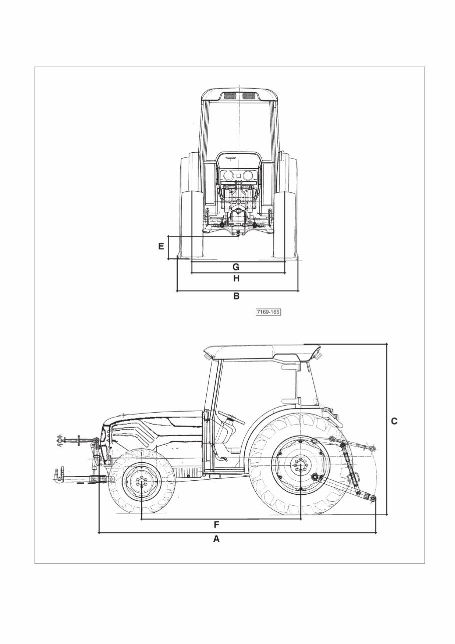
DIMENSIONS AND WEIGHTS AGROCOMPACT AGROCOMPACT F60 70F3 70F4 F80 F90 2 WD 4 WD 2 WD 4 WD lMax. length - without front linkage Without ballast (A) mm 3431 3431 3686 3686 With ballast (A) mm 3671 3671 3801 3801 - with front and rear linkage Without ballast (A) mm 4036 4036 4201 4201 With ballast (A) mm 4136 4136 4301 4301 Width min.-max (B) mm 1207/1507 1207/1507 1495/1691 1495/1691 Max. height. - at safety frame (C) mm 2210 2210 2210 2210 - at cab (standard) (C) mm 2220 2220 2170 2170 Ground clearance (E) mm 230 230 230 230 Wheel base (F) mm 1926 1926 2056 2056 Front track (G) - standard mm 1050 1050 1050 1050 - minimum/maximum mm 954/1476 954/1476 1076/1476 1076/1476 Rear track (H) - standard mm 974 974 1076 1076 - minimum/maximum mm 974/1476 974/1476 1076/1476 1076/1476 Front tyres 7.50-16 320/70R20 7.50-16 320/70R20 Rear tyres 420/70R28 420/70R28 420/70R28 420/70R28 Operating weight (without front lift) - with driver platform Without ballast kg 2150 2180 2290 2370 With ballast kg 2255 2285 2395 2475 - with cab Without ballast kg 2300 2380 2455 2600 With ballast kg 2405 2485 2560 2705 Operating weight (with front lift) - with driver platform Without ballast kg - 2350 - 2540 With ballast kg - 2600 - 2790 - with cab Without ballast kg - 2500 - 2730 With ballast kg - 2750 - 2970 Min. turning radius (without brakes) mm 2905 3115 2905 3115 Weight of front ballast - front cast iron plates kg 140 (70x2) 140 (70x2) 140 (70x2) 140 (70x2) - monolithic block (4WD only) kg - 200 - 200 8
9
PRESCRIBED LUBRICANTS AND FUELS (amounts in litres) Part to be supplied Amt Oil type Engine 6,7 * 60-70-80 HP 11 * 90 HP Oil type Grade API CC, CD, CE, CF-4 Grade CCMC D4 Vis- cosity index Multigrade engine oil SAE 15W 40 Gearbox and Rear axle Power-lift Auxiliary Systems Hydrostatic steering 41 ** API GL 4 SAE 10W 30 Front P.T.O. 2,5 Front - wheel drive • Central axle • Side reductions 6 1,5 x 2 Brakes control and clutch max. level ATF DEXRON II Lubrication points NLGI 2 LITIO/Ca Fuel tank For tractors F60 - 70F3 - 70F4 - F80 - F90 69 litres For tractors F60 - 70F3 - 70F4 - F80 - F90 For tractors with frontal P.T.O. and front lift 58 litres Radiator antifreeze 11 litres * Quantity of oil not including filter (with filter +1.5 litres). ** Indicative value, which may vary by a few litres according to the type of gearbox; always check the level on the tran- smission dipstick. First engine oil change: after 50 hours duty. Intervals between oil changes: every 250 operating hours for lubricants with API-CC specifications every 500 operating hours for lubricants API-CD, API-CE, API-CF-4, CCMC-D4 specifications (see following note). N.B. - Oil change intervals should be halved when: the operating temperature is <10°C (+14°F) the fuel contains more than 0.5% of sulphur “Bio-diesel” fuel is used IMPORTANT: the oil must be changedat least once a year, regardless of the number of operating hours completed. It is advisable to always use the same type of oil when replenishing. 10
Thank you for considering this comprehensive Service Repair Workshop Manual for the Deutz Fahr Agrolux F50 F60 F70 F80 Tractor.
This manual is an invaluable resource for both professional mechanics and DIY enthusiasts, covering every service and repair procedure with easy-to-follow step-by-step instructions and detailed illustrations.
By utilizing this manual, you can significantly reduce repair costs by performing maintenance and repairs on your own. The manual is yours to keep forever, allowing you to print specific pages, chapters, or the entire manual. It can also be conveniently accessed on your tablet or smartphone.
All models, engines, trim, and transmission types are comprehensively covered in this high-quality Service Repair Workshop Manual, providing A-Z repair procedures for every aspect of the vehicle.
Compatible with all PC and MAC computers, tablets, and mobile phones, this downloadable manual requires only Adobe Reader, which is commonly pre-installed or available for free download.
Upon payment confirmation via Visa, MasterCard, or PayPal, the manual will be instantly delivered to the email address provided during checkout, ensuring prompt access to essential repair information.
Customer satisfaction is guaranteed, and with this manual, you can confidently tackle any service or repair task related to the Deutz Fahr Agrolux F50 F60 F70 F80 Tractor.