

SHOP MANUAL
OLIVER
SERIES
1750
1800A
1800B
1800C
1850
Uso Covers
SER
1750
1800B
1800C
1850
1900A
1900B
1900C
1950
1950-T
COCKSHUTT
1 ES
1900B
1900C
1950
1950.T
IDENTIFICATION
Series 1800 and 1900 tractors (series A) begin with serial number
90 525-000 and continue through serial number 124 395-000.
1800 and 1900 series B tractors begin with serial number 124
396-000 and continue through serial number 134 683-000. 1800
and 1900 series C tractors begin with serial number 134 684-000
and continue through serial number 150 420-000. 1850 and 1950
series tractors begin with serial number 150 421-000. 1750 series
tractors begin with serial number 180 537-000. 1950-T series trac-
tors begin with serial number 194 080-000.
Tractor serial number plate is located on rear side of instrument
panel support. On series A 1800 tractors, engine serial number
is stamped on right rear flange of engine. On 1800 series B and
C/ are 1750 and 1950-T and 1850 non-diesel tractors, engine serial
number is stamped along outer edge of timing gear coer mounting
flange directly below generator or alternator. On series 1850
diesel tractors, engine serial number is stamped on c/linder block
directly below injection pump. On series 1900 and 1950 tractors,
engine model and serial numbers are stamped on upper right rear
of cylinder block.
BUILT IN THESE VERSIONS
Rowcrop, Wheatland, Ricefield, Industrial and 4-Wheel Drive.
Rowcrop tractors are available in either dual wheel tricycle or
adjustable front axle versions, while Wheatland, Ricefield, Indus-
trial and 4-Wheel Drive tractors are available with non-adjustable
axles only.
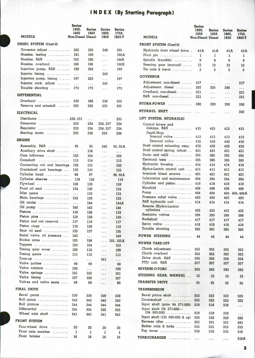
INDEX (By Starting Paragraph)
Series Series
1800, Series Series Series 1800, Series Series Series
1850 1850 1900, 1750, 1850 1850 1900, 1750,
MODELS Non-Diesel Diesel 1950 1950.T MODELS Non-Diesel Diesel 1950 1950-T
BELT PULLEY 350 350 350 350 COOLING SYSTEM
BRAKES 345 345 345 345 Water pump 223 223 ... 223
CARBURETOR Radiator 222 222 251 222
Gasoline 145 145 Thermostat 225 225 255 225
LP-Gaa 158, 172 ... ... ... Fan and Fan Drive ... 252
CLUTCH CREEPER DRIVE 275 275 275 275
Engine clutch adjustment ... 261 261 261 261 DIESEL SYSTEM
Engine clutch R&R 262 262 262 262 Energy cells 211
Engine clutch overhaul 264 264 266 264 Fuel supply pump 214 215 ... 214
Power take-off clutch 355 355 355 355 Fuel system bleeding 176 180 ... 176
I N D E X (By Starting Paragraph)
Series
1800, Series Series Series
1850 1850 1900, 1750,
MODELS Non-Diesel Diesel 1950 1950-T
DIESEL SYSTEM (Cont'd)
Governor adjust 202 205 246 205
Nozzles, testing 181 189 ... 196A
Nozzles, R&R 182 190 ... 196B
Nozzles, overhaul 188 196 ... 196H
Injection pump, R&R 198 204 ... 198
Injector timing ... 243
Injection pump, timing 197 203 ... 197
Injector rack, adjust ... 245
Trouble shooting 173 173 ... 173
DIFFERENTIAL
Overhaul 338 388 338 338
Remove and reinstall 335 335 335 335
ELECTRICAL
Distributor 229,231 231
Generator 233 234 256,257 234
Regulator 233 234 256,257 234
Starting motor 235 236 258 236
ENGINE
Assembly, R&R 95 95 240 95,95A
Auxiliary drive shaft 116
Cam followers 103 104 ... 103
Camshaft 113 114 ... 113
Connecting rod and bearings 130 131 ... 130
Crankshaft and bearings ... 132 133 ... 132
Cylinder head 96 97 ... 96,96A
Cylinder sleeves 119 126 ... 119
Flywheel 138 139 ... 138
Front oil seal 134 136 ... 134
Idler gears 115 ... US
Main bearings 132 133 .., 132
Oil cooler 144 ... 144A
Oil pump 140 142 ... 140
Pistons 119 126 ... 119
Piston pins 128 129 ... 128
Piston and rod removal 117 118 ... 117
Piston rings 119 126 ... 119
Hear oil seal 135 137 ... 135
Reliel valve, oil pressure ... 143 ... ... 143
Rocker arms 105 106 ... 105,105A
Tappets 103 104 ... 103
Timing gear cover 109 UO ... 109
Timing gears Ill H2 ... lU
Tune-up ... 241
Valve guides 98 99 ... 98
Valve rotators 100 ... ... 100
Valve springs 101 102 ... 101
Valve timing 107 108 ... 107
Valves and valve seats 98 99 ... 98
FINAL DRIVE
Bevel gears 339 339 339 339
Bull gears 343 343 343 343
Bull pinions 344 344 344 344
Differential 335 335 335 335
Wheel axle shaft 341 341 341 341
FRONT SYSTEM
Four-wheel drive 20 20 20 20
Front axle member 1 l 1 1
Front bolster 16 16 16 18
Series
1800, Series Series Series
1850 1850 1900, 1750,
MODELS Non-Diesel Diesel 1950 1950-T
FRONT SYSTEM (Cont'd)
Hydraulic front wheel drive.. 41A 41A 41A 41A
Pivot pin 1 1 1 1
Spindle (knuckle) 9 9 9 9
Steering gear (manual) 12 12 12 12
Tie rods & toe-in 2 2 2 2
GOVERNOR
Adjustment, non-diesel 217 ... ... 217
Adjustment, diesel 202 205 248
Overhaul, non-diesel 221 ... ... 221
R&R, non-diesel 221 ... ... 221
HYDRA-POWER 290 290 290 290
HYDRAUL SHIFT 308
LIFT SYSTEM, HYDRAULIC
Control levers and
linkage, R&R 415 415 415 415
Depth-Stop:
Internal valve 413 413 413 413
External valve 430 430 430 430
Draft control actuating assy. 420 420 420 420
Draft control spring, adjust .. 421 421 421 421
Drain and refUl 395 395 395 395
Electrical tests 385 385 385 385
Hydraulic housing 414 414 414 414
Hydra-Lectric control unit . . . 411 411 411 411
Interlock bleed screws ..... 401 401 401 401
Lubrication and maintenance 394 394 394 394
Cylinder and piston 418 418 418 418
Manifold 406 408 406 406
Pump 404 404 404 404,404A
Pressure relief valve 403 403 403 403
H&R hydraulic unit 414 414 414 414
Remote (Hydra-Lectric)
cylinders 422 422 422 422
Restrictor valves 399 399 399 399
Rockshaft 417 417 417 417
Servo valve 416 416 418 416
Trouble shooting 365 365 385 365
POWER STEERING 44 44 44 44
POWER TAKE-OFF
Clutch adjustment 355 355 355 355
Clutch overhaul 382 382 382 382
Drive shaft, R&R 358 358 358 358
PTO unit, R&R 357 357 357 357
REVERSE-O-TORC 283 283 283 283
STEERING GEAR, MANUAL . . 12 12 12 12
TRANSFER DRIVE 35 35 35 35
TRANSMISSION
Bevel pinion shaft 323 323 323 323
Countershaft 322 322 322 322
Input shaft (prior 94 271-000) 318 318 318
Input shaft (94 271-000—
134 683-000) 319 319 319
Input shaft (135 885-000 & up) 320 230 320 320
Reverse idler 331 331 331 331
Shifter rails & forks 315 315 315 315
Top cover 310 310 310 310
TURBOCHARGER _ 2I6A
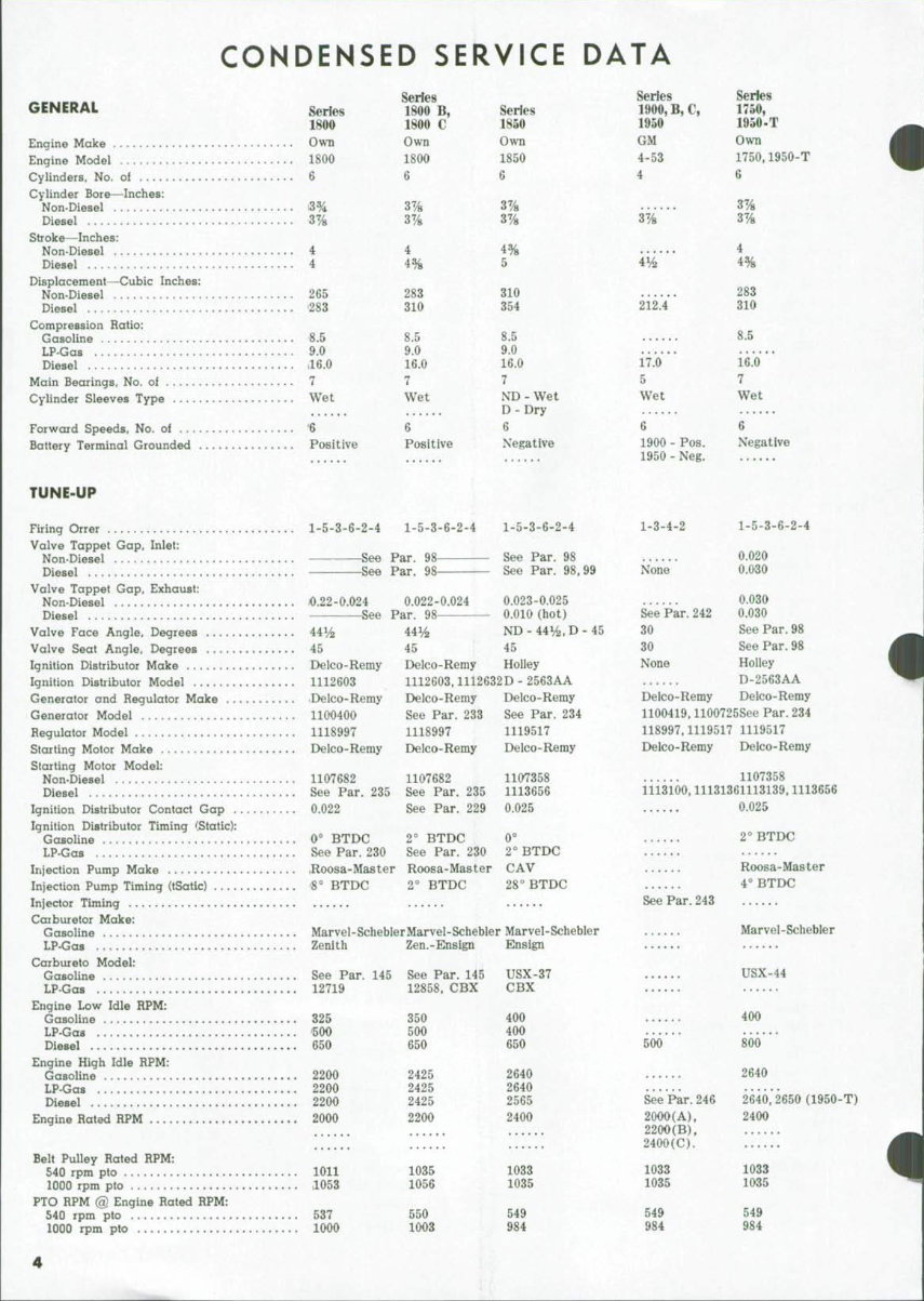
CONDENSED SERVICE DATA
GENERAL Series
1800
Engine Make Own
Engine Model 1800
Cylinders, No. of 6
Cylinder Bore—Inches:
Non-Diesel i3%
Diesel 37/8
Stroke—Inches:
Non-Diesel 4
Diesel 4
Displacement—Cubic Inches:
Non-Diesel 265
Diesel 283
Compression Ratio:
Gasoline 8.5
LP-Gas 9.0
Diesel 1I6.O
Main Bearings, No. of 7
Cylinder Sleeves Type . Wet
Forward Speeds, No. of '6
Battery Terminal Grounded Positive
Series
1800 B,
1800 C
Own
1800
6
3%
3%
4
4%
283
310
8.5
9.0
16.0
7
Wet
6
Positive
Series
1850
Own
1850
6
3%
3y8
4%
5
310
354
8.5
9.0
16.0
7
ND - Wet
D - Dry
6
Negative
Series
1900, B, C,
1950
GM
4-53
4
3%
4^
212.4* *
17.0
5
Wet
6
1900 - Pos.
1950 - Neg.
Series
1750,
1950-T
Own
1750,1950-T
6
3%
3%
4
4%
283
310
8.5
16.0
7
Wet
6
Negative
TUNE-UP
Firing Orrer 1-5-3-6-2-4 1-5-3-6-2-4 1-5-3-6-2-4
Valve Tappet Gap, Inlet:
Non-Diesel See Par. 98 See Par. 98
Diesel See Par. 98 See Par. 98,99
Valve Tappet Gap, Exhaust:
Non-Diesel /0.22-0.024 0.022-0.024 0.023-0.025
Diesel See Par. 98 0.010 (hot)
Valve Face Angle, Degrees 441/2 44y2 ND - 44V2, D - 45
Valve Seat Angle, Degrees 45 45 45
Ignition Distributor Make Delco-Remy Delco-Remy Holley
Ignition Distributor Model 1112603 1112603,1112632D - 2563AA
Generator and Regulator Make .Delco-Remy Delco-Remy Delco-Remy
Generator Model 1100400 See Par. 233 See Par. 234
Regulator Model 1118997 1118997 1119517
Starting Motor Make Delco-Remy Delco-Remy Delco-Remy
Starting Motor Model:
Non-Diesel 1107682 1107682 1107358
Diesel See Par. 235 See Par. 235 1113656
Ignition Distributor Contact Gap 0.022 See Par. 229 0.025
Ignition Distributor Timing (Static):
Gasoline 0° BTDC 2° BTDC 0°
LP-Gas See Par. 230 See Par. 230 2° BTDC
Injection Pump Make Roosa-Master Roosa-Master CAV
Injection Pump Timing (tSatic) 8° BTDC 2° BTDC 28" BTDC
Injector Timing
Caiburetor Make:
Gasoline Marvel-ScheblerMarvel-Schebler Marvel-Schebler
LP-Gas Zenith Zen.-Ensign Ensign
Carbureto Model:
Gasoline See Par. 145 See Par. 145 USX-37
LP-Gas 12719 12858, CBX CBX
Engine Low Idle RPM:
Gasoline 325 350 400
LP-Gas 500 500 400
Diesel 650 650 650
Engine High Idle RPM:
Gasoline 2200 2425 2640
LP-Gas 2200 2425 2640
Diesel 2200 2425 2565
Engine Rated RPM 20O0 220O 2400
Belt Pulley Rated RPM:
540 rpm pto 1011 1035 1033
1000 rpm pto ,1053 1056 1035
PTO RPM @ Engine Hated RPM:
540 rpm pto 537 550 549
1000 rpm pto 1000 1003 984
1-3-4-2
None
1-5-3-6-2-4
0.020
0.030
0.030
See Par. 242 0.030
30 See Par. 98
30 See Par. 98
None Holley
D-2563AA
Delco-Remy Delco-Remy
1100419,1100725See Par. 234
118997,1119517 1119517
Delco-Remy Delco-Remy
1107358
1113100,11131361113139,1113656
0.025
See Par. 243
500
See Par. 246
20OO(A),
2200{B),
2400(C).
1033
1035
549
984
2° BTDC
Roosa-Master
4° BTDC
Marvel-Schebler
USX-44
400
800
2640
2640,2650 (1950-T)
2400
1033
1035
549
984
4
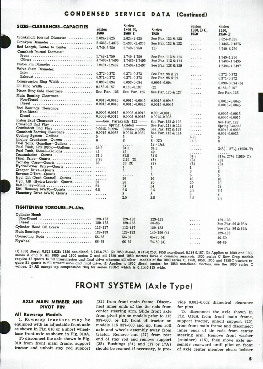
CONDENSED SERVICE DATA (Continued)
SIZES-CLEARANCES-CAPACITIES ^^ ferjes
1800 1800 C
Crankshaft Journal Diameter 2.624-2.625 2.624-2.625
Crankpin Diameter 2.4365-2.4375 2.4365-2.4375
Rod Length, Center to Center 6.749-6.750 6.749-6.750
Camshaft Journal Diameter:
front 1.749-1.750 1.749-1.750
O*ers 1.7485-1.7495 1.7485-1.7495
Piston Pin Diameter 1.2494-1.2497 1.2494-1.2497
Valve Stem Diameter:
Inlet 0.372-0.373 0.372-0.373
Exhaust 0.371-0.372 0.371-0.372
Compression Ring Width 0.093-0.094 0.093-0.094
Oil Ring Width 0.186-0.187 0.186-0.187
Piston Ring Side Clearance See Par. 125 See Par. 125
Main Bearing Clearance:
Non-Diesel 0.0015-0.0045 0.0015-0.0045
I^iesel O.0O15-0.0O45 0.0015-0.0045
Rod Bearings Clearance:
Non-Diesel 0.0005-0.0015 0.00O5-0.0O15
I^iesel 0.0005-0.0015 0.00O5-0.O015
Piston Skirt Clearance — See Paragraph 122
Camshaft End Play Spring Loaded
Crankshaft End Play O.0045-0.0O95 0.0O45-0.0O95
Camshaft Bearing Clearance 0.0015-0.0O35 0.0015-0.0035
Cooling System—Gallons 5 g
Engine Crankcase—Quarts 6 ^f
Fuel Tank, Gasoline—Gallons
Fuel Tank, LPG (80%)—GaUons 36.5*' * 34.*5'
Fuel Tank, Diesel—GaUons 42 42
Transmission—Quarts 31.5 31.5
Final Drive—Quarts 2.75 2.75 (3)
Transfer Case—Quarts 36 36 (3)
Hydra-Power Drive—Quarts 1
Creeper Drive—Quarts 6
Reverse-O-Torc—Quarts ,'.'
Hyd. Lift (Draft Control)—Quarts !!!!!! 10
Hyd. Lift (Hydra-Lectric)—Quarts 20 20
Belt Pulley—Pints 24 24
Diff. Housing (4WD)—Quarts 6.5 6.5
Planetary Drive (4WD) Quarts 8
2.5
TIGHTENING TORQUES-Ft.-Lbs.
Cylinder Head:
Non-Diesel 129-133 129-133
Diesel 129-133 129-133
Cylinder Head Oil Screw 113-117 113-117
Main Bearings 129-133 129-133
Connecting Rods 56-58 56-58
Flywheel 66-69 66-69
Series
Series 1900, B C ,
1850 1950
See Par. 132 & 133
See Par. 132 & 133
(1)
See Par. 113 & 114
See Par. 113 & 114
See Par. 128 & 129
See Par. 98 & 99
See Par. 98 & 99
0.0093-0.094
(2)
See Par. 125 & 127 ......
0.0015-0.0045
0.0015-0.0045
0.0O5-0.0015
0.0015-0.003
See Par. 122 & 126
See Par. 113 & 114
See Par. 132 & 133
See Par. 113 & 114
5 5.25
8 - ND 14,5
12 - Dsl.
34.5
42
31.5 31.5
(3) (3)
(3) (3)
1 1
6 6
5 5
10 10
20 20
24 24
6.5 6.5
8 8
2.5 2.5
129-133
80-85
129-133
140-150 (4)
65-70 (4)
74-80 (4)
Series
1750,
1950-T
2.624-2.625
2.4365-2.4375
6.749-6.750
1.749-1.750
1.7485-1.7495
1.2494-1.2497
0.372-0.373
0.371-0.372
0.093-0;094 (5)
0.186-0.187
See Par. 125
0.0015-0.0045
0.0015-0.0045
0.0005-0.0015
0.0005-0.0015
See Par. 122
Spring Loaded
0.0045-0.0095
0.002-0.0035
5
8
34%, 27% (1950-T)
, 27% (1950-T)
(3)
(3)
1
6
5
10
20
24
6.5
8
129-133
See Par. 96 & 96A
SeePar.96&96A
129-133
46-50
66-69
(1) 1850 diesel. 8.624-8.626; 1850 non^iiesel 6.749-8.750. (2) 1850 diesel 0.249-0.250; 1850 non-diesel 0.188-0.187. (3) Applies to 1800 and 1900
series A and B. All 1800 and 1900 series C and all 1850 and 1950 tractors have a common reservoir. 1800 series C Row Crop models
require 43 quarts to fill transmission and final drive whereas all other models of the 1800 series C. 1750, 1850, 1950 and 1950-T tractors re-
quire 51 quarts to fill transmission and final drive. (4) Applies to 1850 diesel tractor; for 1850 non-diesel tractors, use the 1800 series C
values. (5) All except top compression ring for series 1950-T which is 0.U4-0.115 wide.
FRONT SYSTEM (Axle Type)
AXLE MAIN MEMBER AND
PIVOT PIN
All Rowcrop Models
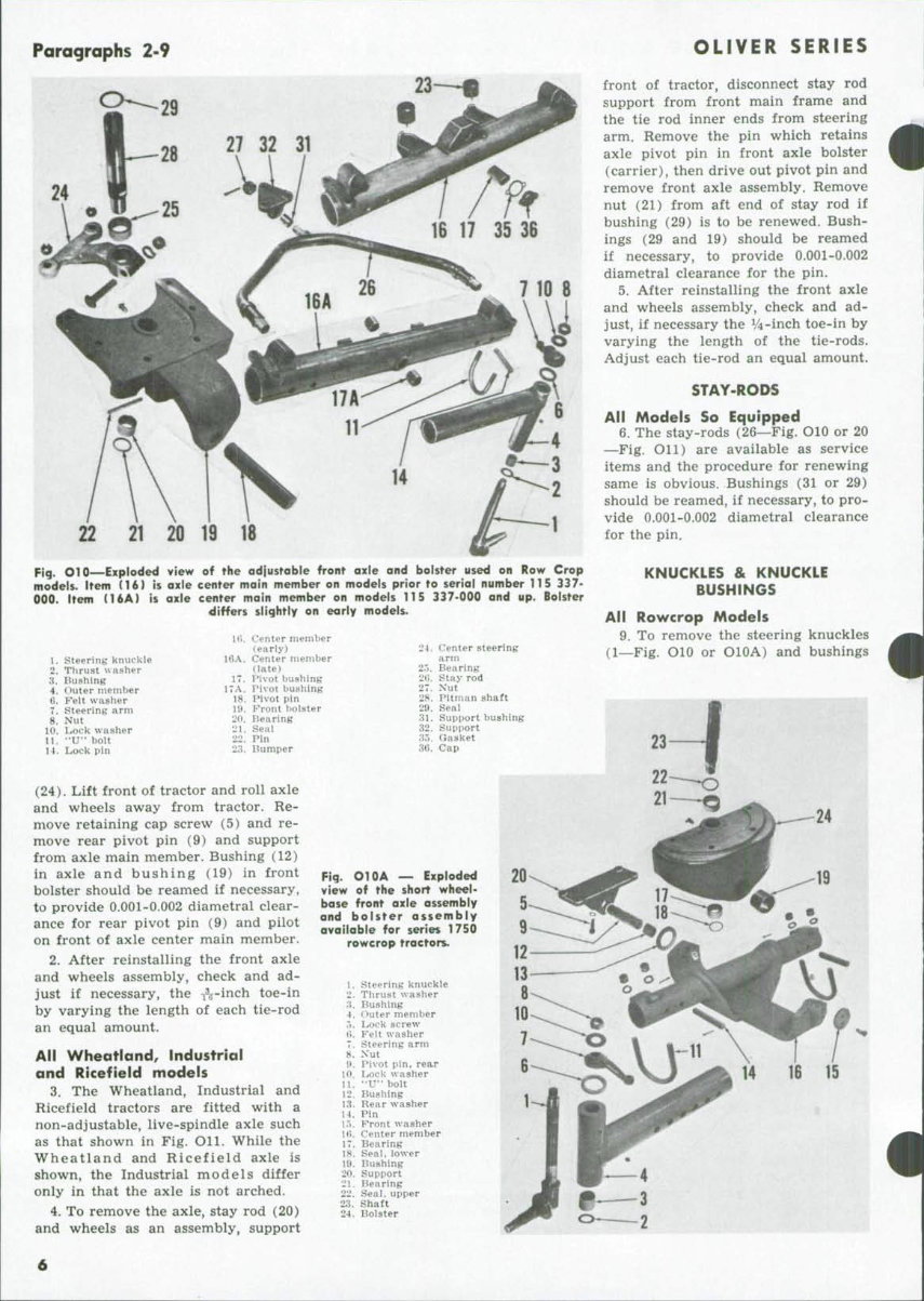
1. Rowcrop tractors may be
equipped with an adjustable front axle
as shown in Fig. 010 or a short wheel-
base front axle as shown in Fig. 010A.
To disconnect the axle shown in Fig.
010 from front main frame, support
tractor and unbolt stay rod support
(32) from front main frame. Discon-
nect inner ends of the tie rods from
center steering arm. Slide front axle
from pivot pin on models prior to 115
337-000, or lift front of tractor on
models 115 337-000 and up, then roll
axle and wheels assembly away from
tractor. Remove nut (27) from rear
end of stay rod and remove support
(32). Bushings (31) and (17 or 17A)
should be reamed if necessary, to pro-
vide 0.001-0.002 diametral clearance
for pins.
To disconnect the axle shown in
Fig. OlOA from front main frame,
support tractor, unbolt support (20)
from front main frame and disconnect
inner ends of tie rods from center
steering arm. Remove front washer
(retainer) (15), then move axle as-
sembly rearward until pilot on front
of axle center member clears bolster
22 21 20 19 18
Fig. O10 Exploded view of the adjustable front axle and bolster used on Row Crop
models. Item (16) is axle center main member on models prior to serial number 115 337-
000. Item (16A) is axle center main member on models 115 337-000 and up. Bolster
differs slightly on early models.
1, steering knuckle
•2. Tlirust washer
'A. lUishing
4. Outer member
ti. Felt washer
7. Steering arm
8. Nut
10. Lock washer
11. "U" bolt
14. Lock pin
Hi. Center member
(early)
16A. Center member
(late)
17. IMvot bushing
17A. Pivot bushing
18. Pivot pin
lt». ?"'ront boister
20. Bearing
21. Seal
22. Pin
23. liumper
24. Center steering
arm
2."». Bearing
2t;. Stay rod
27. Xut
28. Pitman shaft
29. Seal
31. Support bushing
32. Supi)ort
35. Gasket
36. Cap
(24). Lift front of tractor and roll axle
and wheels away from tractor. Re-
move retaining cap screw (5) and re-
move rear pivot pin (9) and support
from axle main member. Bushing (12)
in axle and bushing (19) in front
bolster should be reamed if necessary,
to provide 0.001-0.002 diametral clear-
ance for rear pivot pin (9) and pilot
on front of axle center main member.
2. After reinstalling the front axle
and wheels assembly, check and ad-
just if necessary, the ^-inch toe-in
by varying the length of each tie-rod
an equal amount.
All Wheatland, Industrial
and Ricefield models
3. The Wheatland, Industrial and
Ricefield tractors are fitted with a
non-adjustable, live-spindle axle such
as that shown in Fig. Oil. While the
Wheatland and Ricefield axle is
shown, the Industrial models differ
only in that the axle is not arched.
4. To remove the axle, stay rod (20)
and wheels as an assembly, support
OLIVER SERIES
front of tractor, disconnect stay rod
support from front main frame and
the tie rod inner ends from steering
arm. Remove the pin which retains
axle pivot pin in front axle bolster
(carrier), then drive out pivot pin and
remove front axle assembly. Remove
nut (21) from aft end of stay rod if
bushing (29) is to be renewed. Bush-
ings (29 and 19) should be reamed
if necessary, to provide 0.001-0.002
diametral clearance for the pin.
5. After reinstalling the front axle
and wheels assembly, check and ad-
just, if necessary the V4-inch toe-in by
varying the length of the tie-rods.
Adjust each tie-rod an equal amount.
STAY-ROI>S
All Models So Equipped
6. The stay-rods (26—Fig. OlO or 20
—Fig. OU) are available as service
items and the procedure for renewing
same is obvious. Bushings (31 or 29)
should be reamed, if necessary, to pro-
vide 0.001-0.002 diametral clearance
for the pin.
KNUCKLES & KNUCKLE
BUSHINGS
All Rowcrop Models
9. To remove the steering knuckles
(l_Fig. OlO or OlOA) and bushings
23
24
4
Fig. OlOA — Exploded
view of the short wheel-
base front axle assembly
and bolster assembly
available for series 1750
rowcrop tractors.
1. Steering knuckle
2. Thrust washer
•A. Bushing
4. Outer member
,". Lock screw
*>. Feit washer
7. Steering arm
8. Xut
1>. Pi\ot pin, rear
10. Lock washer
U. "U" bolt
12. Bushing
13. Rear washer
14. Pin
1.". Front washer
KK Center member
17. Bearing
18. Seal, lower
19. Bushing
20. Support
21. Bearing
22. Seal, upper
23. Shaft
24. Bolster
•
1750-1800-1850-1900-1950-1950T
Paragraphs 10-14
b
12
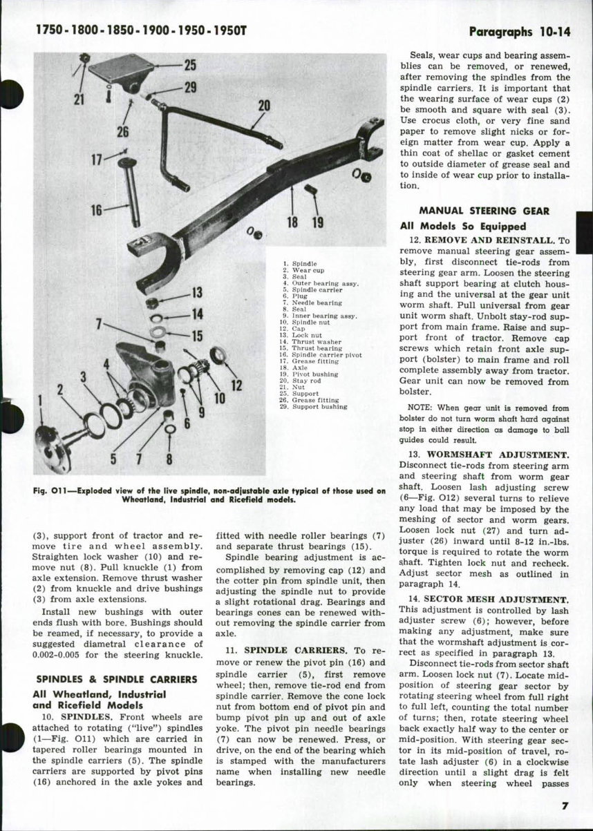
Spindle
Wear cup
Seal
Outer bearing assy.
Spindle carrier
Plug
Needle bearing
Seal
Inner bearing assy.
Spindle nut
Cap
Lrock nut
Thrust washer
Thrust bearing
Spindle carrier pivot
Grease fitting
Axle
IMvot bushing
Stay rod
Nut
Support
Grease fitting
Support bushing
7 8
Fig. Oil—Exploded view of the live spindle, non-adjustable axle typical of those used on
Wheatland, Industrial and Ricefield models.
(3), support front of tractor and re-
move tire and wheel ass em b 1 y.
Straighten lock washer (10) and re-
move nut (8). Pull knuckle (1) from
axle extension. Remove thrust washer
(2) from knuckle and drive bushings
(3) from axle extensions.
Install new bushings with outer
ends flush with bore. Bushings should
be reamed, if necessary, to provide a
suggested diametral clearance of
0.002-0.005 for the steering knuckle.
SPINDLES & SPINDLE CARRIERS
All Wheatland, Industrial
and Ricefield Models
10. SPINDLES. Front wheels are
attached to rotating ("live") spindles
(1—Fig. Oil) which are carried in
tapered roller bearings mounted in
the spindle carriers (5). The spindle
carriers are supported by pivot pins
(16) anchored in the axle yokes and
fitted with needle roller bearings (7)
and separate thrust bearings (15).
Spindle bearing adjustment is ac-
complished by removing cap (12) and
the cotter pin from spindle unit, then
adjusting the spindle nut to provide
a slight rotational drag. Bearings and
bearings cones can be renewed with-
out removing the spindle carrier from
axle.
11. SPINDLE CARRIERS. To re-
move or renew the pivot pin (16) and
spindle carrier (5), first remove
wheel; then, remove tie-rod end from
spindle carrier. Remove the cone lock
nut from bottom end of pivot pin and
bump pivot pin up and out of axle
yoke. The pivot pin needle bearings
(7) can now be renewed. Press, or
drive, on the end of the bearing which
is stamped with the manufacturers
name when installing new needle
bearings.
Seals, wear cups and bearing assem-
blies can be removed, or renewed,
after removing the spindles from the
spindle carriers. It is important that
the wearing surface of wear cups (2)
be smooth and square with seal (3).
Use crocus cloth, or very fine sand
paper to remove slight nicks or for-
eign matter from wear cup. Apply a
thin coat of shellac or gasket cement
to outside diameter of grease seal and
to inside of wear cup prior to installa-
tion.
MANUAL STEERING GEAR
All Models So Equipped
12. REMOVE AND REINSTALL. To
remove manual steering gear assem-
bly, first disconnect tie-rods from
steering gear arm. Loosen the steering
shaft support bearing at clutch hous-
ing and the universal at the gear unit
worm shaft. Pull universal from gear
unit worm shaft. Unbolt stay-rod sup-
port from main frame. Raise and sup-
port front of tractor. Remove cap
screws which retain front axle sup-
port (bolster) to main frame and roll
complete assembly away from tractor.
Gear unit can now be removed from
bolster.
NOTE; When gear unit is removed from
bolster do not turn worm shaft hard against
stop in either direction as damage to ball
guides could result.
13. WORMSHAFT ADJUSTMENT.
Disconnect tie-rods from steering arm
and steering shaft from worm gear
shaft. Loosen lash adjusting screw
(6—Fig. O12) several turns to relieve
any load that may be imposed by the
meshing of sector and worm gears.
Loosen lock nut (27) and turn ad-
juster (26) inward until 8-12 in.-lbs.
torque is required to rotate the worm
sihaft. Tighten lock nut and recheck.
Adjust sector mesh as outlined in
paragraph 14.
14. SECTOR MESH ADJUSTMENT.
This adjustment is controlled by lash
adjuster screw (6); however, before
making any adjustment, make sure
that the wormshaft adjustment is cor-
rect as specified in paragraph 13.
Disconnect tie-rods from sector shaft
arm. Loosen lock nut (7). Locate mid-
position of steering gear sector by
rotating steering wheel from full right
to full left, counting the total number
of turns; then, rotate steering wheel
back exactly half way to the center or
mid-position. With steering gear sec-
tor in its mid-position of travel, ro-
tate lash adjuster (6) in a clockwise
direction until a slight drag is felt
only when steering wheel passes
Paragraphs 15-16
OLIVER SERIES
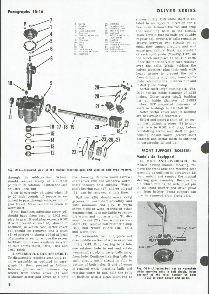
1.
4.
5.
6.
7.
8.
9.
10.
11.
12.
13.
14.
I').
Cover
Gasket
Shim
Lash adju.ster
Jam nut
Pitman shaft and
K'ear
Housing
mug
Seal
Xut
Lock washer
Packing retainer
Packing
16.
17.
18.
19.
20.
21.
22.
23.
26.
27
28!
29.
Bushmg
Bearing cui)
Bearing rone
Steering shaft
Ball nut
9/;i2" steel balls
(106 used)
Gasket
End cover
Bearing adjuster
Lock nut
Ball guides
Guide retainer
Fig. O12—Exploded view of fhe manual steering gear unif used on axle type tractors.
through the mid-position. Wheel
should revolve freely at all other
points in its rotation. Tighten the lash
adjuster lock nut.
Gear is correctly adjusted when 16
to 20 inch pounds of torque is re-
quired to pass through mid-position of
gear travel. Measurement is taken at
wormshaft.
Note: Backlash adjusting screw (6)
should have from zero to 0.002 end
play in gear. If end play exceeds 0.002
it will prevent correct adjustment of
backlash; in which case, sector cover
(1) should be removed and a shim
(5) of correct thickness added at head
of adjuster screw to remove the excess
backlash. Shims are available in a kit
of four shims, 0.063, 0.065, 0.067 and
0.069 thick.
15. OVERHAUL GEAR ASSEMBLY.
To disassemble steering gear unit, re-
move assembly as outlined in para-
graph 12; then, proceed as follows:
Remove pitman arm. Remove cap
screws from sector cover (1) and
withdraw sector and cover as a unit
from housing. Remove worm (screw)
shaft cover (23) and withdraw worm-
shaft through this opening. Worm-
shaft bearing cup (17) and/or oil seal
(11) can be renewed at this time.
Ball nut (20) should move along
grooves in wormshaft smoothly and
with minimum end play. If worm
shows signs of wear, scoring or other
derangement, it is advisable to renew
the worni and nut as a unit. To dis-
assemble nut (20) from worm (screw)
shaft (19), remove ball retainer clamp
(29), ball return guides (28), balls
and worm nut.
To reassemble ball nut, place nut
over middle section of worm as shown
in Fig. O13. Drop bearing balls into
one retainer hole in nut and rotate
wormshaft slowly to carry balls away
from hole. Continue inserting balls in
each circuit until circuit is full to
bottom of both holes. If end of worm
is reached while inserting balls and
rotating worm in nut, hold the balls
in position with a clean blunt rod as
shown in Fig. O13 while shaft is ro-
tated in an opposite direction for a
few turns. Remove the rod and drop
the remaining balls in the circuit.
Make certain that no balls are outside
regular ball circuits. If balls remain in
groove between two circuits or at
ends, they cannot circulate and will
cause gear failure. Next, lay one-half
of each split guide (28—Fig. O12) on
the bench and place 13 balls in each.
Place the other halves of each retainer
over the balls. While holding the
halves together, plug their ends with
heavy grease to prevent the balls
from dropping out; then, insert com-
plete retainer units in worm nut and
install guide clamp.
Sector shaft large bushing (16—Fig.
O12) has an inside diameter of 1.375
inches. Other sector shaft bushing
has an inside diameter of 1.0625
inches. I&T suggested clearance of
shaft in bushings is 0.0015-0.003.
Note: Sector cover and its bushing
are not available separately.
Select and insert a shim (5) on sec-
tor mesh adjusting screw (6) to pro-
vide zero to 0.002 end play, before
reinstalling sector and shaft in gear
housing. Adjust worm (screw) shaft
bearings and sector mesh as outlined
in paragraphs 13 and 14.
FRONT SUPPORT (BOLSTER)
Models So Equipped
16. R&R AND OVERHAUL. On
models having manual steering, re-
move the front axle and steering gear
assembly as outlined in paragraph 12;
then, unbolt and remove the manual
steering gear assembly. Remove the
pin which retains the axle pivot pin
in the front bolster and drive pivot
pin from bolster. Front support can
now be removed from front axle.
BAIL NUT
Fig. on—Aligning ball nut an warmshaft
while inserting balls in ball circuit. Insert
one-half af the total number af balls
C106) in each circuit and guide.
8
1750-1800-1850-1900-1950-1950T
Paragraphs 17-20
Fig. O13A—View of front support from
Wheatland model tracror with power steer-
ing. While shapes may differ, the operating
parts of front supports remain basically
the same.
1.
2.
4.
5.
Steering arm
Thrust washer
Seal
Pitman shaft
6.
7.
8*.
9.
10.
Bearing:
Bolster
Bearing
Seal
Pivot pin
On those models equipped with
power steering, remove the power
steering unit or power steering cylin-
der as outlined in paragraph 51 or 88
and the front axle assembly as out-
lined in paragraph 1. Unbolt bolster
and remove from front main frame.
Remove clamp bolt from pitman arm,
mark the position of pitman arm and
shaft, then remove pitman arm and
thrust washer from front bolster. Oil
seals and needle bearings can now be
removed. See Fig. O13A.
When reinstalling needle bearings,
drive on end which is stamped with
number and align the oil .holes in
bearings with the oil holes in bolster.
Install oil seals with lips toward out-
side (away from pitman arm).
FRONT SYSTEM
(Tricycle Type)
FRONT SUPPORT ASSEMBLY
All Rowcrop Models
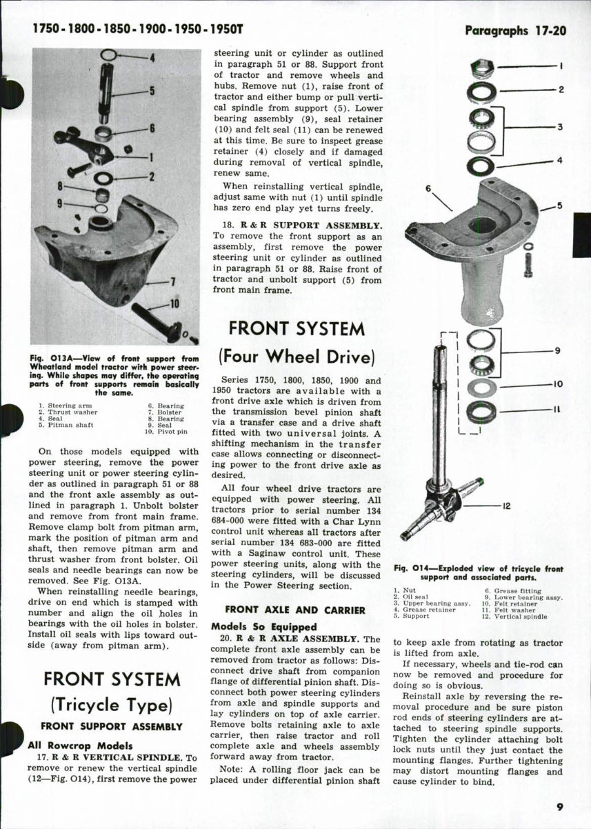
17. R & R VERTICAL SPINDLE. To
remove or renew the vertical spindle
(12—Fig. O14), first remove the power
steering unit or cylinder as outlined
in paragraph 51 or 88. Support front
of tractor and remove wheels and
hubs. Remove nut (1), raise front of
tractor and either bump or pull verti-
cal spindle from support (5). Lower
bearing assembly (9), seal retainer
(10) and felt seal (11) can be renewed
at this time. Be sure to inspect grease
retainer (4) closely and if damaged
during removal of vertical spindle,
renew same.
When reinstalling vertical spindle,
adjust same with nut (1) until spindle
has zero end play yet turns freely.
18. R&R SUPPORT ASSEMBLY.
To remove the front support as an
assembly, first remove the power
steering unit or cylinder as outlined
in paragraph 51 or 88. Raise front of
tractor and unbolt support (5) from
front main frame.
FRONT SYSTEM
(Four Wheel Drive)
Series 1750, 1800, 1850, 1900 and
1950 tractors are available with a
front drive axle which is driven from
the transmission bevel pinion shaft
via a transfer case and a drive shaft
fitted with two universal joints. A
shifting mechanism in the transfer
case allows connecting or disconnect-
ing power to the front drive axle as
desired.
All four wheel drive tractors are
equipped with power steering. All
tractors prior to serial number 134
684-000 were fitted with a Char Lynn
control unit whereas all tractors after
serial number 134 683-000 are fitted
with a Saginaw control unit. These
power steering units, along with the
steering cylinders, will be discussed
in the Power Steering section.
FRONT AXLE AND CARRIER
Models So Equipped
20. R & R AXLE ASSEMBLY. The
complete front axle assembly can be
removed from tractor as follows: Dis-
connect drive shaft from companion
flange of differential pinion shaft. Dis-
connect both power steering cylinders
from axle and spindle supports and
lay cylinders on top of axle carrier.
Remove bolts retaining axle to axle
carrier, then raise tractor and roll
complete axle and wheels assembly
forward away from tractor.
Note: A rolling floor jack can be
placed under differential pinion shaft
Fig. O14—Exploded view of tricycle front
support and associared parts.
1. Nut
2. Oil seal
3. Upper bearing assy.
4. Grease retainer
5. Support
6. Grease fitting
9. Lower bearing assy.
10. Felt retainer
11. Felt washer
12. Vertical spindle
to keep axle from rotating as tractor
is lifted from axle.
If necessary, wheels and tie-rod can
now be removed and procedure for
doing so is obvious.
Reinstall axle by reversing the re-
moval procedure and be sure piston
rod ends of steering cylinders are at-
tached to steering spindle supports.
Tighten the cylinder attaching bolt
lock nuts until they just contact the
mounting flanges. Further tightening
may distort mounting flanges and
cause cylinder to bind.
Paragraphs 21-26
OLIVER SERIES
21. R & R AXLE CARRIER. To re-
move axle carrier, first remove front
axle as outlined in paragraph 20, then
secure steering cylinders to tractor
frame. Place a rolling floor jack under
axle carrier and take weight of car-
rier. Remove pivot pin retaining cap
screws, slide pivot pins from pivot
supports and lower axle carrier from
tractor. If necessary, pivot supports
can be removed from tractor frame.
Bushings in axle carrier can now
be renewed. Bushings are pre-sized
and should require no final sizing if
carefully installed.
22. OVERHAUL FRONT AXLE.
Overhaul of the front drive axle as-
sembly will be discussed as four oper-
ations; the planet spider assembly, the
hub assembly, the spindle support as-
sembly and the differential and carrier
assembly. All operations except the
differential and carrier overhaul can
be accomplished without removing the
front drive axle from tractor. Both
outer ends of axle are identical, hence,
only one outer end will be discussed.
23. PLANET SPIDER. To overhaul
the planet spider assembly, support
outer end of axle and remove the tire
and rim. Remove relief valve from
center of planet spider, remove plug
from wheel hub and drain planet
spider. Remove cap screws which re-
tain planet spider to wheel hub and
the two puller hole cap screws. Use
two of the removed retaining cap
screws in the puller holes and pull
planet spider assembly from wheel
hub.
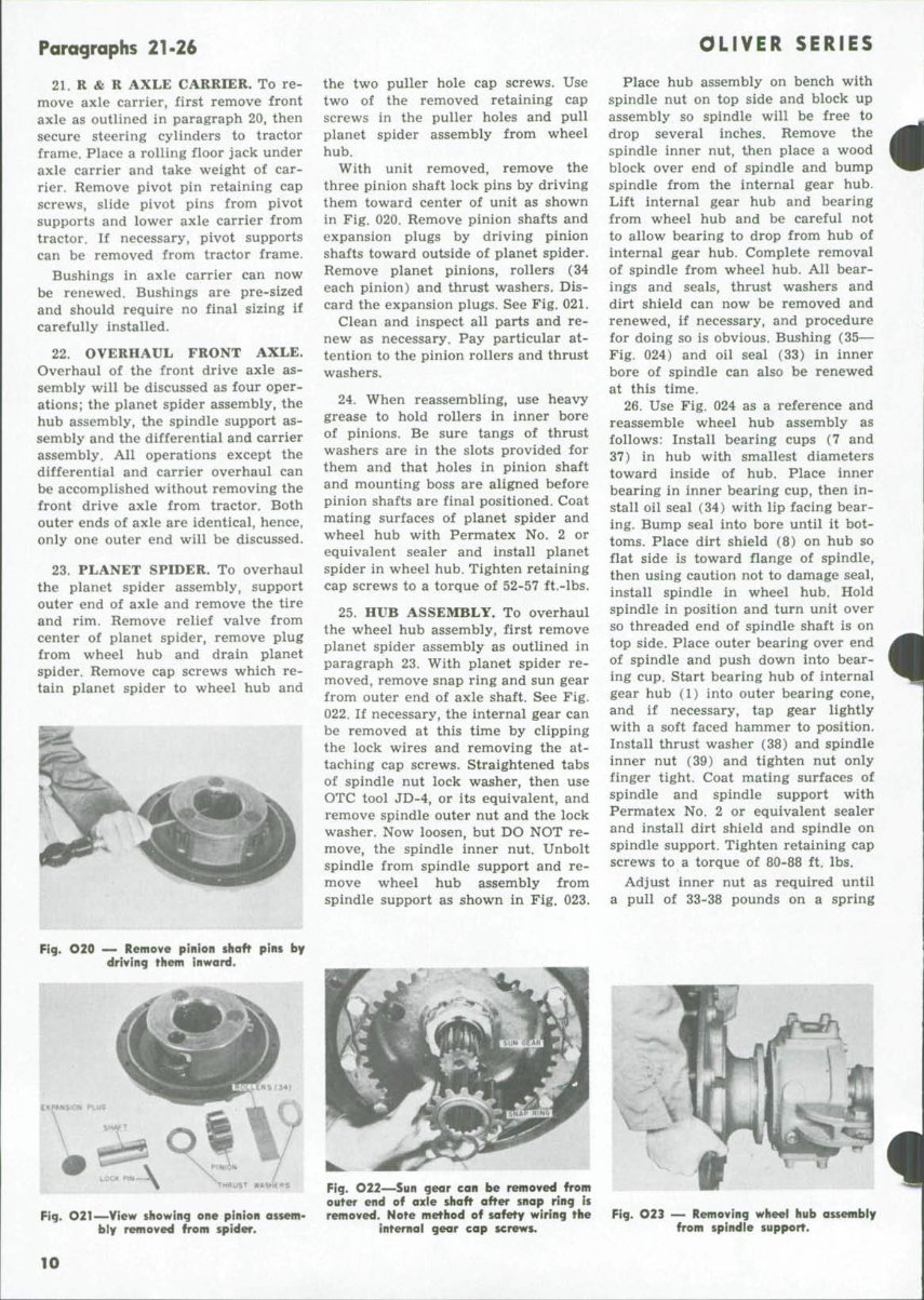
With unit removed, remove the
three pinion shaft lock pins by driving
them toward center of unit as shown
in Fig. 020. Remove pinion shafts and
expansion plugs by driving pinion
shafts toward outside of planet spider.
Remove planet pinions, rollers (34
each pinion) and thrust washers. Dis-
card the expansion plugs. See Fig. 021.
Clean and inspect all parts and re-
new as necessary. Pay particular at-
tention to the pinion rollers and thrust
washers.
24. When reassembling, use heavy
grease to hold rollers in inner bore
of pinions. Be sure tangs of thrust
washers are in the slots provided for
them and that holes in pinion shaft
and mounting boss are aligned before
pinion shafts are final positioned. Coat
mating surfaces of planet spider and
wheel hub with Permatex No. 2 or
equivalent sealer and install planet
spider in wheel hub. Tighten retaining
cap screws to a torque of 52-57 ft.-lbs.
25. HUB ASSEMBLY. To overhaul
the wheel hub assembly, first remove
planet spider assembly as outlined in
paragraph 23. With planet spider re-
moved, remove snap ring and sun gear
from outer end of axle shaft. See Fig.
022. If necessary, the internal gear can
be removed at this time by clipping
the lock wires and removing the at-
taching cap screws. Straightened tabs
of spindle nut lock washer, then use
OTC tool JD-4, or its equivalent, and
remove spindle outer nut and the lock
washer. Now loosen, but DO NOT re-
move, the spindle inner nut. Unbolt
spindle from spindle support and re-
move wheel hub assembly from
spindle support as shown in Fig. 023.
Place hub assembly on bench with
spindle nut on top side and block up
assembly so spindle will be free to
drop several inches. Remove the
spindle inner nut, then place a wood
block over end of spindle and bump
spindle from the internal gear hub.
Lift internal gear hub and bearing
from wheel hub and be careful not
to allow bearing to drop from hub of
internal gear hub. Complete removal
of spindle from wheel hub. All bear-
ings and seals, thrust washers and
dirt shield can now be removed and
renewed, if necessary, and procedure
for doing so is obvious. Bushing (35—
Fig. 024) and oil seal (33) in inner
bore of spindle can also be renewed
at this time.
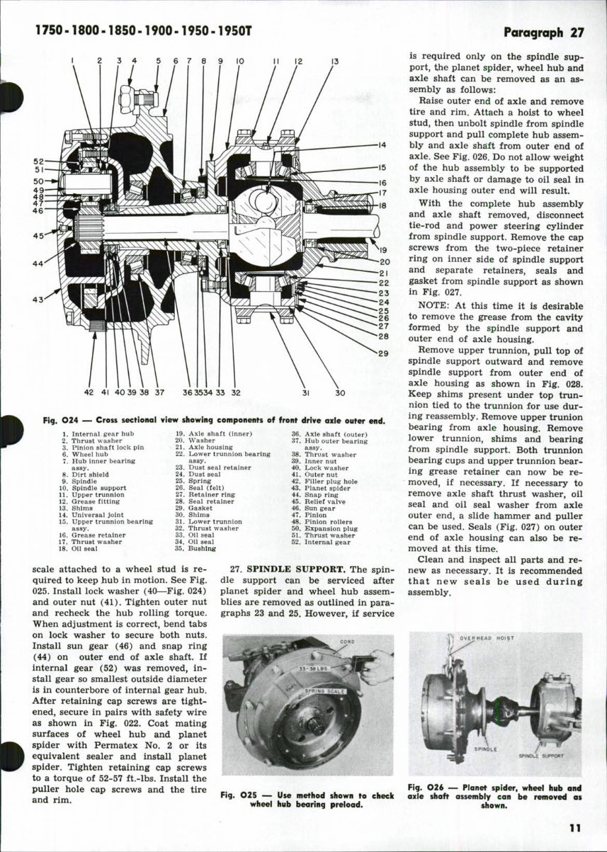
26. Use Fig. 024 as a reference and
reassemble wheel hub assembly as
follows: Install bearing cups (7 and
37) in hub with smallest diameters
toward inside of hub. Place inner
bearing in inner bearing cup, then in-
stall oil seal (34) with lip facing bear-
ing. Bump seal into bore until it bot-
toms. Place dirt shield (8) on hub so
flat side is toward flange of spindle,
then using caution not to damage seal,
install spindle in wheel hub. Hold
spindle in position and turn unit over
so threaded end of spindle shaft is on
top side. Place outer bearing over end
of spindle and push down into bear-
ing cup. Start bearing hub of internal
gear hub (1) into outer bearing cone,
and if necessary, tap gear lightly
with a soft faced hammer to position.
Install thrust washer (38) and spindle
inner nut (39) and tighten nut only
finger tight. Coat mating surfaces of
spindle and spindle support with
Permatex No. 2 or equivalent sealer
and install dirt shield and spindle on
spindle support. Tighten retaining cap
screws to a torque of 80-88 ft. lbs.
Adjust inner nut as required until
a pull of 33-38 pounds on a spring
Fig. O20 — Remove pinion shaft pins by
driving them inward.
Ftg. O21—View showing one pinion assem-
bly removed from spider.
Fig. O22—Sun gear can be removed from
outer end of axle shaft after snop ring is
removed. Note method of safety wiring the
internal gear cap screws.
Fig. O23 — Removing wheel hub assembly
from spindle support.
10
1750-1800-1850-1900-1950-1950T
I 2 3 4 5 6 7 8 9 10
Ii 12
14
44
43
42 41 40 39 38 37 36 3534 33 32 30
Fig. O24 — Cross secfionol view showing componenrs of fronr drive axle outer end.
1. Internal gear hub 19.
2. Thrust washer 20.
3. Pinion shaft lock pin 21.
6. Wheel hub 22.
7. Hub inner bearing
assy. 23.
8. Dirt shield 24.
9. Spindle 25.
10. Spindle support 26.
11. Upper trunnion 27.
12. Grease fitting 28.
13. Shims 29.
14. Universal joint 30.
15. Upper trunnion bearing 31.
assy. 32.
16. Grease retainer 33.
17. Thrust washer 34.
18. Oil seal 35.
Axle shaft (inner) 36.
Washer 37.
Axie housing
Lower trunnion bearing 38.
assy. 39.
Dust seal retainer 40.
Dust seal 41.
Spring 42.
Seal (felt) 43.
Retainer ring 44.
Seal retainer 45.
Gasket 46.
Shims 47.
Lower trunnion 48.
Thrust washer 50.
Oil seal 51.
Oil seal 52.
Bushing
Axle shaft (outer)
Hub outer bearing
assy.
Thrust washer
Inner nut
Lock washer
Outer nut
Filler plug hole
Planet spider
Snap ring
Relief valve
Sun gear
Pinion
Pinion rollers
Expansion plug
Thrust washer
Internal gear
scale attached to a wheel stud is re-
quired to keep hub in motion. See Fig.
025. Install lock washer (40—Fig. 024)
and outer nut (41). Tighten outer nut
and recheck the hub rolling torque.
When adjustment is correct, bend tabs
on lock washer to secure both nuts.
Install sun gear (46) and snap ring
(44) on outer end of axle shaft. If
internal gear (52) was removed, in-
stall gear so smallest outside diameter
is in counterbore of internal gear hub.
After retaining cap screws are tight-
ened, secure in pairs with safety wire
as shown in Fig. 022. Coat mating
surfaces of wheel hub and planet
spider with Permatex No. 2 or its
equivalent sealer and install planet
spider. Tighten retaining cap screws
to a torque of 52-57 ft,-lbs. Install the
puller hole cap screws and the tire
and rim.
27. SPINDLE SUPPORT. The spin-
dle support can be serviced after
planet spider and wheel hub assem-
blies are removed as outlined in para-
graphs 23 and 25. However, if service
Paragraph 27
is required only on the spindle sup-
port, the planet spider, wheel hub and
axle shaft can be removed as an as-
sembly as follows:
Raise outer end of axle and remove
tire and rim. Attach a hoist to wheel
stud, then unbolt spindle from spindle
support and pull complete hub assem-
bly and axle shaft from outer end of
axle. See Fig. 026. Do not allow weight
of the hub assembly to be supported
by axle shaft or damage to oil seal in
axle housing outer end will result.
With the complete hub assembly
and axle shaft removed, disconnect
tie-rod and power steering cylinder
from spindle support. Remove the cap
screws from the two-piece retainer
ring on inner side of spindle support
and separate retainers, seals and
gasket from spindle support as shown
in Fig. 027.
NOTE: At this time it is desirable
to remove the grease from the cavity
formed by the spindle support and
outer end of axle housing.
Remove upper trunnion, pull top of
spindle support outward and remove
spindle support from outer end of
axle housing as shown in Fig. 028.
Keep shims present under top trun-
nion tied to the trunnion for use dur-
ing reassembly. Remove upper trunion
bearing from axle housing. Remove
lower trunnion, shims and bearing
from spindle support. Both trunnion
bearing cups and upper trunnion bear-
ing grease retainer can now be re-
moved, if necessary. If necessary to
remove axle shaft thrust washer, oil
seal and oil seal washer from axle
outer end, a slide hammer and puller
can be used. Seals (Fig. 027) on outer
end of axle housing can also be re-
moved at this time.
Clean and inspect all parts and re-
new as necessary. It is recommended
that new seals be used during
assembly.
OVE^
Fig. O25 — Use method shown ro eheck
wheel hub bearing preload.
Fig. O26 — Planet spider, wheel hub and
axle shaft assembly can be removed as
shown.
11
You're Reading a Preview
What's Included?
Fast Download Speeds
Online & Offline Access
Access PDF Contents & Bookmarks
Full Search Facility
Print one or all pages of your manual
$41.99
Oliver & Cockshutt 1750 1800 1900 1950 Series Tractor Service & Repair Manual
Viewed 11 Times Today

What's Included?
Fast Download Speeds
Online & Offline Access
Access PDF Contents & Bookmarks
Full Search Facility
Print one or all pages of your manual
$41.99

Secure transaction
What's Included?
Fast Download Speeds
Online & Offline Access
Access PDF Contents & Bookmarks
Full Search Facility
Print one or all pages of your manual
Description
Thank you for considering this comprehensive Workshop Service Repair Manual for the Oliver & Cockshutt 1750 1800 1900 1950 Series Tractor.
This manual is an invaluable resource for both professional mechanics and DIY enthusiasts, covering every service and repair procedure with easy-to-follow step-by-step instructions and detailed pictures.
By utilizing this manual, you can significantly reduce repair costs by performing the repairs yourself. It provides the flexibility to print specific pages, chapters, or the entire manual, and can also be conveniently accessed on your tablet or smartphone.
Models Covered:
- All Models/Engines/Trim/Transmissions Types Are Covered
Contents:
- This high-quality Service Repair Workshop Manual encompasses all repair procedures from A to Z, ensuring that every repair and service procedure is comprehensively addressed.
Computer Requirements:
- This downloadable Manual is compatible with all PC & MAC Computers, tablets, and mobile phones. It only requires Adobe Reader, which is typically pre-installed on most computers or can be downloaded for free.
Delivery:
- Upon payment confirmation via Visa, MasterCard, or PayPal, the manual will be instantly emailed to the address provided during checkout.
Customer satisfaction is guaranteed with this Workshop Service Repair Manual.


