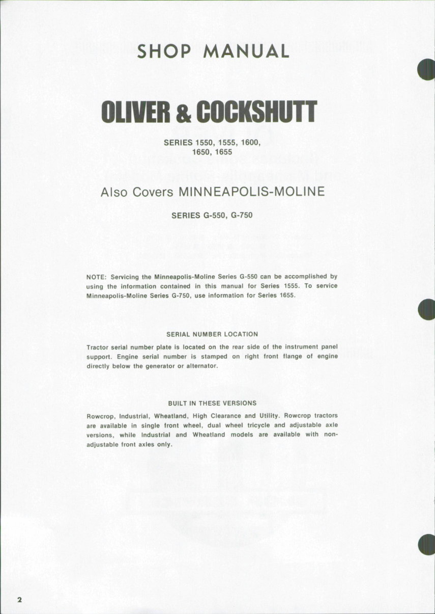
SHOP MANUAL , OlIVER & COGKSHUTT SERIES 1550,1555, 1600, 1650, 1655 Also Covers MINNEAPOLIS-MOLINE SERIES G-550, G-750 NOTE: Servicing the Minneapolis-Moline Series G-550 can be accomplished by using the information contained in this manual for Series 1555. To service Minneapolis-Moline Series G-750, use information for Series 1655. SERIAL NUMBER LOCATION Tractor serial number plate is located on the rear side of the instrument panel support. Engine serial number is stamped on right front flange of engine directly below the generator or alternator. BUILT IN THESE VERSIONS Rowcrop, Industrial, Wheatland, High Clearance and Utility. Rowcrop tractors are available in single front wheel, dual wheel tricycle and adjustable axle versions, while Industrial and Wheatland models are available with non- adjustable front axles only.
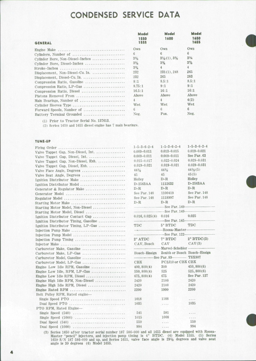
CONDENSED SERVICE DATA Moder 1550 GENERAL 1555 Engine Make Own Cylinders, Number of 6 Cylinder Bore, Non-Diesel-Inches 3% Cylinder Bore. Diesel-Inches 3% Stroke-Inches 3% Displacement, Non-Diesel-Cu. In 232 Displacement, Diesel-Cu. In 232 Compression Ratio, Gasoline 8:1 Compression Ratio, LP-Gas 8.75:1 Compression Ratio, Diesel 16.5:1 Pistons Removed From Above Main Bearings, Number of 4 Cylinder Sleeves Type Wet Forward Speeds, Number of 6 Battery Terminal Grounded Neg. (1) Prior to Tractor Serial No. 137613. (2) Series 1650 and 1655 diesel engine has 7 main bearings. Model 1600 Own 6 3V2(1),3% 3% 4 231(1),248 265 8.5:1 9:1 16:1 Above 4 Wet 6 Pos. Model 1650 1655 Own 6 33/4 3% 4 265 283 8.5:1 9:1 16:1 Above 4(2) Wet 6 Neg. TUNE-UP Firing Order 1-5-3-6-2-4 1-5-3-6-2-4 1-5-3-6-2-4 Valve Tappet Gap. Non-Diesel, Int 0.009-0.011 0.013-0.015 0.019-0.021 Valve Tappet Gap, Diesel, Int 0.009-0.011 0.009-0.011 See Par. 63 Valve Tappet Gap, Non-Diesel, Exh 0.015-0.017 0.022-0.024 0.029-0.031 Valve Tappet Gap, Diesel, Exh 0.019-0.021 0.019-0.021 0.029-0.031 Valve Face Angle, Degrees 441/2 44^2 44V2(5) Valve Seat Angle, Degrees 45 45 45(5) Ignition Distributor Make Holley D-R Holley Ignition Distributor Model D-2563AA 1112632 D-2563AA Generator & Regulator Make D-H D-R D-R Generator Model See Par. 148 1100419 See Par. 148 Regulator Model See Par. 148 1118997 See Par. 148 Starting Motor Make D-R D-R D-R Starting Motor Model, Non-Diesel See Par. 149 Starting Motor Model, Diesel — See Par. 149 Ignition Distributor Contact Gap 0.016,0.025(4) 0.016 0.025 Ignition Distributor Timing, Gasoline —< -See Par. 145 Ignition Distributor Timing, LP-Gas TDC 5° BTDC TDC Injection Pump Make — Roosa-Master Injection Pump Model — See Par. 122 Injection Pump Timing 2° ATDC 7° BTDC 2" BTDC(3) Injector Make CAV, Bosch CAV CAV(3) Carburetor Make, Gasoline Marvel-Schebler Carburetor Make, LP-Gas Bosch-Ensign Zenith or Bosch Bosch-Ensign Carburetor Modei, Gasoline — See Par. 89 TSX807 Carburetor Model, LP-Gas CBX PC2J10' or CBX CBX Engine Low Idle RPM. Gasoline 400,800(4) 300 450,800(6) Engine Low Idie, RPM, LP-Gas 550,800(4) 525 525,800(6) Engine Low Idle RPM, Diesel 675,800(4) 675 See Par. 127 Engine High Idle RPM, Non-Diesel 2420 2100 2420 Engine High Idie RPM, Diesel 2420 2100 2420 Engine Rated RPM 2200 1900 2200 Beit Puliey RPM, Rated engine— Singie Speed PTO 1018 1188 Dual Speed PTO 1035 .... 1035 PTO RPM, Rated Engine- Single Speed (540) 541 581 Single Speed (1000) 1015 1008 Dual Speed (540) 550 .... 550 Dual Speed (1000) 994 .... 994 (3) Series 1650 after tractor serial number 187 586-000 and all 1655 diesel are equipped with Roosa- Master *'pencii" injectors, and injection pump timing is 4° BTDC. (4) Model 1555. (5) Series 1650 S/N 187 586-000 and up, and Series 1655, valve face angle is 29^^ degrees and valve seat angle is 30 degrees (6) Model 1655.
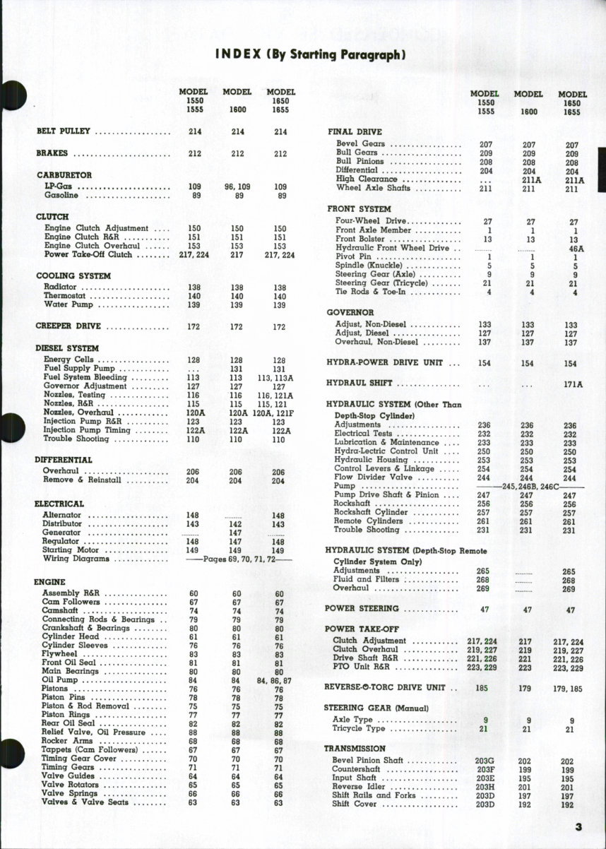
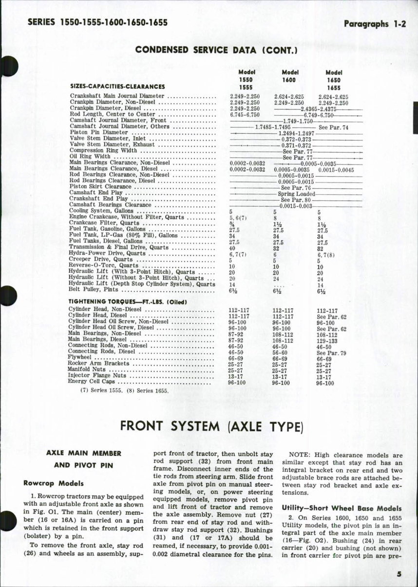
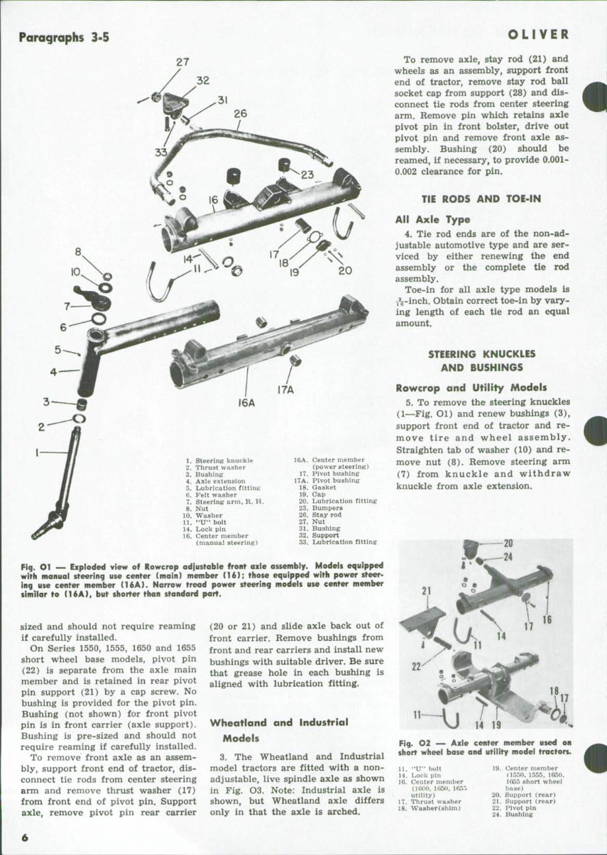
SERIES 1550.15S5-1600-1650.1655 Paragraphs 1.2 2.624-2.625 2.624-2.625 2.249-2.250 2.249-2.250 --^2.4365-2.4375 6.749-6.750^- 0.0005-0.0035 ^— 0.0005-0.0035 0.0015-0.0045 - 0.0005-0.0015 - 0.0005-0.0015 - See Par. 76 • - Spring Loaded — - See Par. 80 0.0015-0.003 CONDENSED SERVICE DATA (CONTJ Model Model Model 1550 UOO 1650 SIZES-CAPACITIES-CLEARANCES 1555 U55 Crankshaft Main Journal Diameter 2.249-2.250 Crankpin Diameter, Non-Diesei 2.249-2.250 Crankpin Diameter, Diesel 2.249-2.250 Rod Length, Center to Center 6.745-6.750 Camshaft Journal Diameter, Front 1.749-1.750- Camshaft Journai Diameter, Others —1.7485-1.7495 See Par. 74 Piston Pin Diameter _ 1.2494-1.2497 '- Valve Stem Diameter, Inlet 0.372-0.373 Valve Stem Diameter, Exhaust .—. 0.371-o!372 Compression Ring Width See Par 77 ^- Oil Ring Width See Par. 77- Main Bearings Clearance, Non-Diesel 0.0002-0.0032 Main Bearings Clearance, Diesel 0.0002-0.0032 Rod Bearings Clearance, Non-Diesel Rod Bearings Clearance, Diesel Piston Skirt Ciearance _. Camshaft End Piay _. Crankshaft End Play ._, Camshaft Bearings Clearance — Cooling System, Gallons 5 5 Engine Crankcase, Without Fiiter, Quarts 5,6(7) 8 Crankcase Filter, Quarts % xy^ Fuel Tank, Gasoline, Gallons 27 5 27 5 Fuel Tank, LP-Gas (80% Fill), Gallons 34* 34* Fuei Tanks, Diesel, Gallons 27.5 27 5 Transmission & Final Drive, Quarts 40 32* Hydra-Power Drive, Quarts 6,7(7) 6 Creeper Drive, Quarts 5' 5 Reverse-0-Torc, Quarts 10 10 Hydraulic Lift (With 3-Point Hitch), Quarts 20 20 Hydraulic Lift (Without 3-Point Hitch), Quarts ... 20 24 Hydraulic Lift (Depth Stop Cylinder System), Quarts 14 Belt Pulley, Pints 6^ 6^^ * TIGHTENING TORpUES^FT.-LBS. (Oiled) Cylinder Head, Non-Diesel 112-117 112-117 Cylinder Head, Diesel 112-117 112-117 Cylinder Head Oil Screw, Non-Diesel 96-100 96-100 Cylinder Head Oii Screw, Diesel 96-100 96-100 Main Bearings, Non-Diesel 87-92 108-112 Main Bearings, Diesel 87-92 108-112 Connecting Rods, Non-Diesel 46-50 46-50 Connecting Rods, Diesel 46-50 56-60 Flywheel 66-69 66-69 Rocker Arm Brackets 25-27 25-27 Manif oid Nuts 25-27 25-27 Injector Flange Nuts 13..17 13.17 Energy Cell Caps 96-100 96-100 (7) Series 1555. (8) Series 1655. 5 8 27.5 34 27.5 32 6,7(8) 5 10 20 24 14 Hi 112-117 See Par. 62 96-100 See Par. 62 108-112 129-133 46-50 See Par. 79 66-69 25-27 25-27 13-17 96-100 FRONT SYSTEM (AXLE TYPE) AXLE MAIN MEMBER AND PIVOT PIN Rowcrop Models 1. Rowcrop tractors may be equipped with an adjustable front axle as shown in Fig. 01. The main (center) mem- ber (16 or 16A) is carried on a pin which is retained in the front support (bolster) by a pin. To remove the front axle, stay rod (26) and w,heels as an assembly, sup- port front of tractor, then unbolt stay rod support (32) from front main frame. Disconnect inner ends of the tie rods from steering arm. Slide front axle from pivot pin on manual steer- ing models, or, on power steering equipped models, remove pivot pin and lift front of tractor and remove the axle assembly. Remove nut (27) from rear end of stay rod and with- draw stay rod support (32). Bushings (31) and (17 or 17A) should be reamed, if necessary, to provide 0.001- 0.002 diametral clearance for the pins. NOTE: High clearance models are similar except that stay rod has an integral bracket on rear end and two adjustable brace rods are attached be- tween stay rod bracket and axle ex- tensions. Utility-Short Wheel Base Models 2. On Series 1600, 1650 and 1655 Utility models, the pivot pin is an in- tegral part of the axle main member a6~-Fig. O2). Bushing (24) in rear carrier (20) and bushing (not shown) in front carrier for pivot pin are pre-
Paragraphs 3.5 27 32 10 1. Steerint,' knuckle 2. Thrust washer 3. Bushing 4. Axle extension 5. Lubrication fitting 6. Felt washer 7. Steering arm, R. H, 8. Nut 10. Washer 11. "U" bolt 14. Lock pin 16. Center member (manual steering) 16A. Center member (power steering) 17. Pivot bushing 17A. Pivot bushing 18. Gasket 19. Cap 20. Lubrication fitting 23. Bumpers 26. Stay rod 27. Nut 31. Bushing 32. Support 33. Lubrication fitting Fig. O1 — Exploded view of Rowcrop odiustoble front oxie ossembly. Models equipped wifh manuol steering use center (main) member (16); those equipped with power steer- ing use center member (16A). Narrow tread power steering models use center member simllor to (16A), but shorter than standard part. sized and should not require reaming if carefully installed. On Series 1550, 1555, 1650 and 1655 short wheel base models, pivot pin (22) is separate from the axle main member and is retained in rear pivot pin support (21) by a cap screw. No bushing is provided for the pivot pin. Bushing (not shown) for front pivot pin is in front carrier (axle support). Bushing is pre-sized and should not require reaming if carefully installed. To remove front axle as an assem- bly, support front end of tractor, dis- connect tie rods from center steering arm and remove thrust washer (17) from front end of pivot pin. Support axle, remove pivot pin rear carrier (20 or 21) and slide axle back out of front carrier. Remove bushings from front and rear carriers and install new bushings with suitable driver. Be sure that grease hole in each bushing is aligned with lubrication fitting. Wheatland and Industrial Models 3. The Wheatland and Industrial model tractors are fitted with a non- adjustable, live spindle axle as shown in Fig. O3. Note: Industrial axle is shown, but Wheatland axle differs only in that the axle is arched. OLIVER To remove axle, stay rod (21) and wheels as an assembly, support front end of tractor, remove stay rod ball socket cap from support (28) and dis- connect tie rods from center steering arm. Remove pin whiqh retains axle pivot pin in front bolster, drive out pivot pin and remove front axle as- sembly. Bushing (20) should be reamed, if necessary, to provide 0.001- 0.002 clearance for pin. TIE RODS AND TOE-IN All Axle Type 4. Tie rod ends are of the non-ad- justable automotive type and are ser- viced by either renewing the end assembly or the complete tie rod assembly. Toe-in for all axle type models is 1%-inch. Obtain correct toe-in by vary- ing length of each tie rod an equal amount. STEERING KNUCKLES AND BUSHINGS Rowcrop and Utility Models 5. To remove the steering knuckles (1—Fig, Ol) and renew bushings (3), support front end of tractor and re- move tire and wheel assembly. Straighten tab of washer (10) and re- move nut (8). Remove steering arm (7) from knuckle and withdraw knuckle from axle extension. 11~J I / VJ 14 Fig. O2 — Axle center member u$ed on short wheel base and utility model tractors. 11, "U" boit 14. Lock pin 16. Center member (lGOO, 1(J5<», HJ55 utility) 17. Thrust washer 18. Washer (shim) 19. Center member (lSriO, 1555. l(>50, Ifio5 short wheel base) 20. Support (rear) 21. Support (rear) 22. Pivot pin 24. Bushing
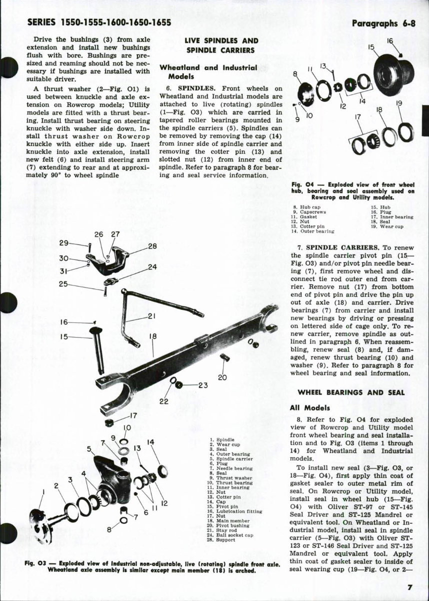
SERIES 1550-1555-1600-1650-1655 Paragraphs 6-8 Drive the bushings (3) from axle extension and install new bushings flush with bore. Bushings are pre- sized and reaming should not be nec- essary if bushings are installed with suitable driver. A thrust washer (2—Fig. Ol) is used between knuckle and axle ex- tension on Rowcrop models; Utility models are fitted with a thrust bear- ing. Install thrust bearing on steering knuckle with washer side down. In- stall thrust washer on Rowcrop knuckle with either side up. Insert knuckle into axle extension, install new felt (6) and install steering arm (7) extending to rear and at approxi- mately 90*" to wheel spindle LIVE SPINDLES AND SPINDLE CARRIERS Wheatland and Industrial Models 6. SPINDLES. Front wheels on Wheatland and Industrial models are attached to live (rotating) spindles (1—Fig. O3) which are carried in tapered roller bearings mounted in the spindle carriers (5). Spindles can be removed by removing the cap (14) from inner side of spindle carrier and removing the cotter pin (13) and slotted nut (12) from inner end of spindle. Refer to paragraph 8 for bear- ing and seal service information. 26 27 1. Spindle 2. Wear cup 3. Seal 4. Outer bearing 5. Spindle carrier 6. Plug 7. Needle bearing 8. Seal 9. Thrust washer 10. Thrust bearing 11. Inner bearing 12. Nut 13. Cotter pin 14. Cap 15. Pivot pin 16. Lubrication fitting 17. Nut 18. Main member 20. Pivot bushing 21. Stay rod 24. Ball socket cap 28. Support Fig. 04 — Exploded view of front wheel hub, bearing and seal assembly used on Rowcrop and Utility models. 8. Hub cap 9. Capscrews 11. Gasket 12. Nut 13. Cotter pin 14. Outer bearing 15. Hub 16. Plu^r 17. Inner bearing 18. Seal 19. Wear cup Fig. Ot — Exploded view of Industrial non-adfustable, live Crotating) spindle front axle. Wheatland axle assembly is similar except moin member (18} is arched. 7. SPINDLE CARRIERS. To renew the spindle carrier pivot pin (15— Fig. O3) and/or pivot pin needle bear- ing (7), first remove wheel and dis- connect tie rod outer end from car- rier. Remove nut (17) from bottom end of pivot pin and drive the pin up out of axle (18) and carrier. Drive bearings (7) from carrier and install new bearings by driving or pressing on lettered side of cage only. To re- new carrier, remove spindle as out- lined in paragraph 6. When reassem- bling, renew seal (8) and, if dam- aged, renew thrust bearing (10) and washer (9), Refer to paragraph 8 for wheel bearing and seal information. WHEEL BEARINGS AND SEAL All Models 8. Refer to Fig. O4 for exploded view of Rowcrop and Utility model front wheel bearing and seal installa- tion and to Fig. O3 (items 1 through 14) for Wheatland and Industrial models. To install new seal (3—Fig. O3, or 18—Fig. O4), first apply thin coat of gasket sealer to outer metal rim of seal. On Rowcrop or Utility model, install seal in wheel hub (15—^Flg. O4) with Oliver ST-97 or ST-145 Seal Driver and ST-125 Mandrel or equivalent tool. On Wheatland or In- dustrial model, install seal in spindle carrier (5—Fig. O3) with Oliver ST- 123 or ST-146 Seal Driver and ST-125 Mandrel or equivalent tool. Apply thin coat of gasket sealer to inside of seal wearing cup (19—Fig. O4, or 2—
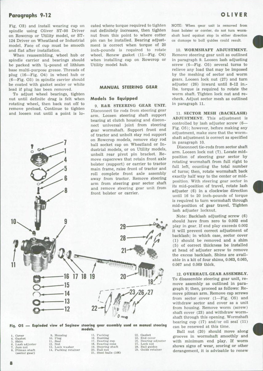
Paragraphs 9-12 Fig. O3) and install wearing cup on spindle using Oliver ST-98 Driver on Rowcrop or Utility model, or ST- 124 Driver on Wheatland or Industrial model. Face of cup must be smooth and flat after installation. When reassembling, wheel hub or spindle carrier and bearings should be packed with %-pound of lithium base multi-purpose grease. Threads of plug (16—Fig. O4) in wheel hub or (6—Fig. O3) in spindle carrier should be coated with gasket sealer or white lead if plug has been removed. To adjust wheel bearings, tighten nut until definite drag is felt when rotating wheel, then back nut off to remove preload. Continue to tighten and loosen nut until a point is lo- cated w,here torque required to tighten nut definitely increases, then tighten nut from this point to where cotter pin can be installed. Bearing adjust- ment is correct when torque of 20 inch-pounds is required to rotate wheel. Renew gasket (11—Fig. O4) when installing cap on Rowcrop or Utility model hub. MANUAL STEERING GEAR Models So Equipped 9. R&R STEERING GEAR UNIT. Disconnect tie rods from steering gear arm. Loosen steering shaft support bearing at clutch housing and discon- nect universal joint from steering gear wormshaft. Support front end of tractor and unbolt stay rod support on Rowcrop models, remove stay rod ball socket cap on Wheatland or In- dustrial models, or on Utility models, unbolt rear pivot pin bracket. Re- move capscrews that retain front axle bolster (support) or carrier to tractor main frame, raise front of tractor and roll complete front axle assembly away from tractor. Remove steering arm from steering gear sector shaft and remove steering gear unit from front bolster or carrier. 16 17 18 19 15 14 13 12 ^^23/26/27 Fig. O5 Exploded view of Soglnow steering gear ossembly used on manual steering models. 1. Cover 4, Gasket 5. Shim fi. I^ash adjuster 7. Jam nut 8. Pitman shaft (sector gear) 9. Housing 10. Plug 11. Seal 12. Nut 13. Lock washer 14. Packing retainer 15. Packing 16. Bushing 17. Bearing cup 18. Bearing cone 19. Steering shaft 20. Bali nut 21. Steel balls (106) 22. Gasket 23. End cover '2G. Bearing adjuster 27, Lock nut 28, Ball guides 29, Guide retainer OLIVER NOTE: When gear unit is removed from front bolster or carrier, do not turn worm- shaft hard against stop in either direction as damage to ball guides could result, 10. WORMSHAFT ADJUSTMENT. Remove steering gear unit as outlined in paragraph 9. Loosen lash adjusting screw (6—Fig. O5) several turns to relieve any load that may be imposed by the meshing of sector and worm gears. Loosen lock nut (27) and turn adjuster (26) inward until 8-12 in.- lbs. torque is required to rotate the worm shaft. Tighten lock nut and re- check. Adjust sector mesh as outlined in paragraph 11. 11. SECTOR MESH (BACKLASH) ADJUSTMENT. This adjustment is controlled by lash adjuster screw (6— Fig, O5); however, before making any adjustment, make sure that the worm- shaft adjustment is correct as specified in paragraph 10. Disconnect tie-rods from sector shaft arm. Loosen lock nut (7). Locate mid- position of steering gear sector by rotating wormshaft from full right to full left, counting the total number of turns; then, rotate worm.shaft back exactly half way to the center or mid- position. With steering gear sector in its mid-position of travel, rotate lash adjuster (6) in a clockwise direction until 16 to 20 inch-pounds of torque is required to turn wormshaft through mid-position of gear travel. Tighten lash adjuster locknut. Note: Backlash adjusting screw (6) should have from zero to 0.002 end play in gear. If end play exceeds 0.002 it will prevent correct adjustment of backlash; in which case, sector cover (1) should be removed and a shim (5) of correct thickness be installed at head of adjuster screw to remove the excess backlash. Shims are avail- able in a kit of four shims, 0.063, 0.065, 0.067 and 0.069 thick. 12. OVERHAUL GEAR ASSEMBLY. To disassemble steering gear unit, re- move assembly as outlined in para- graph 9; then, proceed as follows: Re- move pitman arm. Remove cap screws from sector cover (1—Fig. O5) and withdraw sector and cover as a unit from housing. Remove worm (screw) shaft cover (23) and withdraw worm- shaft through this opening. Wormshaft bearing cup (17) and/or oil seal (11) can be renewed at this time. Ball nut (20) should move along grooves in wormshaft smoothly and with minimum end play. If worm shows signs of wear, scoring or other derangement, it is advisable to renew 8
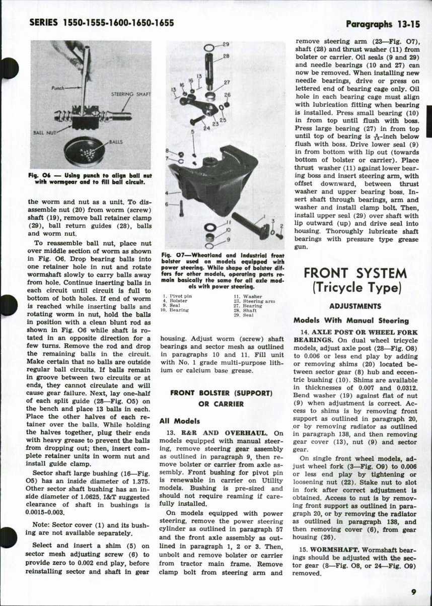
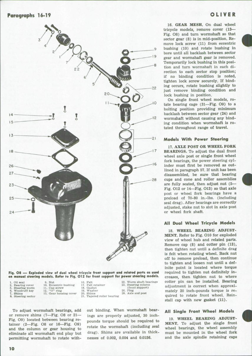
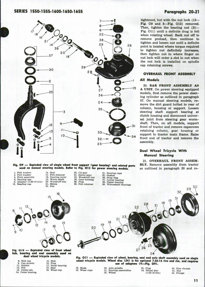
SERIES 1550-1555-1600-1650-1655 SAIL NUT- SHAFT Fig. O6 — Using punch to align ball nut with wormgear and to fill ball circuit. the worm and nut as a xmit. To dis- assemble nut (20) from worm (screw) shaft (19), remove ball retainer clamp (29), ball return guides (28), balls and worm nut. To reassemble ball nut, place nut over middle section of worm as shown in Fig. O6. Drop bearing balls into one retainer hole in nut and rotate worms^haft slowly to carry balls away from hole. Continue inserting balls in each circuit until circuit is full to bottom of both holes. If end of worm is reached while inserting balls and rotating worm in nut, hold the balls in position with a clean blunt rod as shown in Fig. O6 while shaft is ro- tated in an opposite direction for a few turns. Remove the rod and drop the remaining balls in the circuit. Make certain that no balls are outside regular ball circuits. If balls remain in groove between two circuits or at ends, they cannot circulate and will cause gear failure. Next, lay one^half of each split guide (28—Fig. O5) on the bench and place 13 balls in each. Place the other halves of each re- tainer over the balls. While holding the halves together, plug their ends with heavy grease to prevent the balls from dropping out; then, insert com- plete retainer units in worm nut and install guide clamp. Sector shaft large bushing (16—Fig. O5) has an inside diameter of 1.375. Other sector shaft bushing has an in- side diameter of 1.0625. I&T suggested clearance of shaft in bushings is 0.0015-0.003. Note: Sector cover (1) and its bush- ing are not available separately. Select and insert a shim (5) on sector mesh adjusting screw (6) to provide zero to 0.002 end play, before reinstalling sector and shaft in gear Fig. OZ^Wheatland and Industrial front bolster used on models equipped with power steering. While shape of bolster dif- fers for other models, operating parts re- main basicaiiy the same for all axle mod- els with power steering. 1. Pivot pin 4, Bolster 9. Seal 10. Bearing 11. Washer 23. Steering arm 27. Bearing 28. Shaft 29. Seat housing. Adjust worm (screw) shaft bearings and sector mesh as outlined in paragraphs 10 and 11. Fill unit with No. 1 grade multi-purpose lith- ium or calcium base grease. FRONT BOLSTER (SUPPORT) OR CARRIER All Models 13. R&R AND OVERHAUL. On models equipped with manual steer- ing, remove steering gear assembly as outlined in paragraph 9, then re- move bolster or carrier from axle as- sembly. Front bushing for pivot pin is renewable in carrier on Utility models. Bushing is pre-sized and should not require reaming if care- fully installed. On models equipped with power steering, remove the power steering cylinder as outlined in paragraph 57 and the front axle assembly as out- lined in paragraph 1, 2 or 3. Then, unbolt and remove bolster or carrier from tractor main frame. Remove clamp bolt from steering arm and Paragraphs T3-15 remove steering arm (23—Fig. O7), shaft (28) and thrust washer (11) from bolster or carrier. Oil seals (9 and 29) and needle bearings (10 and 27) can now be removed. When installing new needle bearings, drive or press on lettered end of bearing cage only. Oil hole in each bearing cage must align with lubrication fitting when bearing is installed. Press small bearing (10) in from top until flush with boss. Press large bearing (27) in from top until top of bearing is ^-inch below flush with boss. Drive lower seal (9) in from bottom with lip out (towards bottom of bolster or carrier). Place thrust washer (11) against lower bear- ing boss and insert steering arm, with offset downward, between thrust was;her and upper bearing boss. In- sert shaft through bearings, arm and washer and install clamp bolt Then, install upper seal (29) over shaft with lip outward (up) and drive seal into housing. Thoroughly lubricate shaft bearings with pressure type grease gun. FRONT SYSTEM (Tricycle Type) ADJUSTMENTS Models With Manual Steering 14. AXLE POST OR WHEEL FORK BEARINGS. On dual wheel tricycle models, adjust axle post (28—Fig. O8) to 0.006 or less end play by adding or removing shims (20) located be- tween sector gear (8) hub and eccen- tric bushing (10). Shims are available in thicknesses of 0.007 and 0.0312. Bend washer (19) against flat of nut (9) when adjustment is correct. Ac- cess to shims is by removing front support as outlined in paragraph 20, or by removing radiator as outlined in paragraph 138, and then removing gear cover (13), nut (9) and sector gear. On single front wheel models, ad- just wheel fork (3—Fig. O9) to 0.006 or less end play by tightening or loosening nut (22). Stake nut to slot in fork after correct adjustment is obtained. Access to nut is by remov- ing front support as outlined in para- graph 20, or by removing the radiator as outlined in paragraph 138, and then removing cover (6), from gear housing (26). 15. WORMSHAFT. Wormshaft bear- ings should be adjusted with the sec- tor gear (8—Fig. O8, or 24—Fig. O9) removed.
Paragraphs 16-19 16 28 24 Fig. O8 — Exploded view of duoi wheei tricycle front support and related porTs as used on manuai steering models. Refer to Fig. O12 for front supporT for power steering models. 1. on seal 2. Bearing cover 5. Steering womi 6. Woodruff key 7. Shima 8. Steering sector 9, Nut 10, Eccentric bushing 11, Cap screw 12, "O" ring 13, Gear housing cover 16, Felt 17, Felt retainer 18, Gasket 19, Washer 20, Shims 21, Tapered roller bearing 22, Worm shaft bearings 23, Steering column (front support) 26, Plug 28. Axie and post OLIVER 16. GEAR MESH. On dual wjieel tricycle models, remove cover (13— Fig. 08) and turn wormshaft so that sector gear (8) is in mid-position. Re- move lock screw (11) from eccentric bushing (10) and rotate bushing in bore until all backlash between sector gear and wormshaft gear is removed. Temporarily lock bushing in this posi- tion and turn wormshaft in each di- rection to each sector stop position; if no binding condition is noted, tighten lock screw securely. If bind- ing occurs, rotate bushing slightly to just remove binding condition and lock bushing in position. On single front wheel models, ro- tate bearing cage (31—Fig. O9) to a bolting position providing minimum backlash between sector gear (24) and wormshaft without causing any bind- ing condition when wormshaft is ro- tated throughout range of travel. Modeis With Power Steering 17. AXLE POST OR WHEEL FORK BEARINGS. To adjust the dual front wheel axle post or single front wheel fork bearings, the power steering cyl- inder must first be removed as out- lined in paragraph 57. If unit has been disassembled, be sure that bearing cups and cone and roller assemblies are fully seated, then adjust nut (5— Fig. O12 or 14^Fig. O13) so that axle post or wheel fork bearings have a preload of 70-80 in.-lbs. (including seal drag). After bearings are correctly adjusted, stake nut to slot in axle post or wheel fork shaft. Aii Dual Wheei Tricycie Modeis 18. WHEEL BEARING ADJUST- MENT. Refer to Fig. OlO for exploded view of wheel hub and related parts. Remove cap (8) and cotter pin (13), then tighten nut until a definite drag is felt when rotating wheel. Back nut off to remove preload, then continue to tighten and loosen nut until a def- inite point is located where torque required to tighten nut definitely in- creases, then tighten nut to where cotter pin can be installed. Bearing adjustment is correct when approxi- mately 20 inch-pounds torque is re- quired to rotate front wheel. Rein- stall cap with new gasket (11). To adjust wormshaft bearings, add or remove shims (7—Fig. O8 or 21— Fig. O9) located between bearing re- tainer (2—Fig. O8 or 16—Fig. O9) and the column or gear housing to eliminate all wormshaft end play but permitting wormshaft to rotate with- out binding. When wormshaft bear- ings are properly adjusted, 30 inch- pounds torque should be required to rotate the wormshaft (including seal drag). Shims are available in thick- nesses of 0.002, 0.004 and 0.0156. Ail Singie Front Wheei Models 19. WHEEL BEARING ADJUST- MENT. To adjust t,he single front wheel bearings, the wheel assembly must be mounted in the wheel fork and the axle spindle retaining caps 10
SERIES 1550-1555-1600-1650-1655 26 Fig. O9 ~ Expioded view of tingie wheei front uippert (gear iiousing) and related parts used on manuai steering modeis. Refer to Fig. O13 for power steering models. Paragraphs 20-21 tightened, but with the nut lock (13— Fig. 09 and 8—Fig. O13) removed. Then, tighten the bearing nut (31— Fig. Oil) until a definite drag is felt when rotating wheel. Back nut off to remove preload, then continue to tighten and loosen nut until a definite point is located where torque required to tighten nut definitely increases, then tighten nut to where finger on nut lock will enter a slot in nut when the nut lock is installed on spindle cap retaining screws. OVERHAUL FRONT ASSEMBLY All Modeis 20. R&R FRONT ASSEMBLY AS A UNIT. On power steering equipped models, first remove the power steer- ing cylinder as outlined in paragraph 57. On manual steering models, re- move the dirt guard bolted to rear of column, housing or support. Loosen steering shaft support bearing at clutch housing and disconnect univer- sal joint from steering gear worm- shaft. Then, on all models, support front of tractor and remove capscrews retaining column, gear housing or support to tractor main frame. Raise front end of tractor and remove the assembly. Dual Wheel Trlc/cle With Manual Steering 21. OVERHAUL FRONT ASSEM- BLY. Remove assembly from tractor as outlined in paragraph 20 and re- 1. Felt washer 2. Felt washer 3. Fork assembly 6. Bearing cap 9. Adapter (7.50-16 tire) 12. Bearing cap 14. Seal 15. Felt retainer 16. Bearing cover 19. Worm shaft 20. Woodruff key 21. Shims 22. Nut 23. Oii seal 24. Sector gear 25. Woodruff key 26. Gear housing 29. Plug 30, Felt retainer 31. Bearing cage 35. Gasket 36. Snap ring 37. Lower bearing 38. Upper bearing 39. Wormshaft beaHngs Pig. OlO — Exploded vfew of front wheei hub, bearing and seai assembly used on dual wheel tricycle models. 8. Hub cap 9. Cap screws 11. Gasket 12. Nut 13. Cotter pin 14. Outer bearing 15. Hub 16. Plug 17. Inner bearing 18. Seal 19. Wear cup Fig. Oil — Exploded view of wheel, bearing, seal and axle shaft assembly used on single wheel tricycle models. Wheel disc (24) is for optionai 7.50-16 tire and rim, and r«quires use of adapters (9—Fig. O9). 18. Seals 19. Wear cups 20. Axie spindle 21. Bearing assemblies 22. Wheel 23. Piug 24. Wheel disc (7.50-16 rtm) 26. Rim ciamps 31. Nut 32. Flange 11
You're Reading a Preview
What's Included?
Lifetime Access
Fast Download Speeds
Online & Offline Access
Access PDF Contents & Bookmarks
Full Search Facility
Print one or all pages of your manual
$41.99
Oliver & Cockshutt 1550 1555 1600 1650 1655 Series Tractor Complete Workshop Service Repair Manual
Thank you for considering this comprehensive Workshop Service Repair Manual for the Oliver & Cockshutt 1550, 1555, 1600, 1650, and 1655 Series Tractors.
This manual is an invaluable resource for both professional mechanics and DIY enthusiasts, covering every service and repair procedure with easy-to-follow step-by-step instructions and detailed illustrations.
By utilizing this manual, you can significantly reduce repair costs by performing the work yourself. The manual is yours to keep forever, allowing you to print specific pages, chapters, or the entire manual. It can also be conveniently accessed on your tablet or smartphone.
Models Covered:
All Models/Engines/Trim/Transmissions Types Are Covered
Contents:
This high-quality manual encompasses all repair procedures from A to Z, ensuring that every repair and service procedure is comprehensively addressed.
Computer Requirements:
This manual is compatible with all PC & MAC Computers, tablets, and mobile phones. The only software required is Adobe Reader, which is typically pre-installed on most computers or can be downloaded for free.
Delivery:
Upon payment confirmation via Visa, MasterCard, or PayPal, the manual will be instantly emailed to the address provided during checkout.
Customer satisfaction is guaranteed with this Workshop Service Repair Manual.
Reviews
Q&A
Recently Viewed
5,521,897Happy Clients
2,594,462eManuals
1,120,453Trusted Sellers
15Years in Business
Price:
Actual Price:
Oliver & Cockshutt 1550 1555 1600 1650 1655 Series Tractor Complete Workshop Service Repair Manual



 Lifetime Access




