Contents INTRODUCTION DISTRIBUTION SYSTEMS ............................................................. A PRIMARY HYDRAULIC POWER SYSTEM ............................................... A.10.A PRIMARY HYDRAULIC POWER SYSTEM Electro-hydraulic remote valve .............. A.10.C SECONDARY HYDRAULIC POWER SYSTEM........................................... A.12.A HYDRAULIC COMMAND SYSTEM ....................................................... A.14.A ELECTRICAL POWER SYSTEM ......................................................... A.30.A ELECTRONIC SYSTEM .................................................................. A.50.A FAULT CODES ............................................................................ A.50.A PNEUMATIC SYSTEM .................................................................... A.20.A POWER PRODUCTION ................................................................. B ENGINE ................................................................................... B.10.A FUEL AND INJECTION SYSTEM ......................................................... B.20.A AIR INTAKE SYSTEM ..................................................................... B.30.A EXHAUST SYSTEM....................................................................... B.40.A ENGINE COOLANT SYSTEM ............................................................ B.50.A ENGINE COOLANT SYSTEM Fan reversing system ..................................... B.50.B LUBRICATION SYSTEM .................................................................. B.60.A STARTING SYSTEM ...................................................................... B.80.A POWER TRAIN ............................................................................. C TRANSMISSION Continuously Variable Transmission (CVT) ........................... C.20.G REAR PTO Hydraulic ..................................................................... C.40.C FRONT PTO Hydraulic ................................................................... C.42.C TRAVELLING ................................................................................ D FRONT AXLE ............................................................................. D.10.A REAR AXLE ............................................................................... D.12.A 2WD-4WD SYSTEM Hydraulic ........................................................... D.14.C STEERING Hydraulic..................................................................... D.20.C STEERING AutoPilot ...................................................................... D.20.E 84172758A 0 06/02/2009
SERVICE BRAKE Mechanical ............................................................ D.30.B SERVICE BRAKE Hydraulic.............................................................. D.30.C SERVICE BRAKE Pneumatic ............................................................. D.30.E PARKING BRAKE Mechanical ............................................................ D.32.B BRAKE CONNECTION Hydraulic ........................................................ D.34.C SUSPENSION Hydraulic ................................................................. D.40.C WHEELS AND TRACKS Wheels......................................................... D.50.C PARKING BRAKE Electronic ............................................................. D.32.D BODY AND STRUCTURE .............................................................. E FRAME Primary frame .................................................................... E.10.B USER PLATFORM ........................................................................ E.34.A ENVIRONMENT CONTROL Heating, ventilation and air-conditioning .................... E.40.D SHIELD .................................................................................... E.20.A WORKING ARM ............................................................................ H HITCH Front hitch ......................................................................... H.10.B HITCH Rear hitch......................................................................... H.10.C HITCH Electronic draft control ............................................................ H.10.D 84172758A 0 06/02/2009
INTRODUCTION Foreword Technical Information This manual has been produced by a new technical information system. This new system is designed to deliver technical information electronically through CD-ROM and in paper manuals. A coding system called ICE has been developed to link the technical information to other Product Support functions e.g. Warranty. Technical information is written to support the maintenance and service of the functions or systems on a customers machine. When a customer has a concern on his machine it is usually because a function or system on his machine is not working at all, is not working efficiently, or is not responding correctly to his commands. When you refer to the technical information in this manual to resolve that customers concern, you will find all the information classified using the new ICE coding, according to the functions or systems on that machine. Once you have located the technical information for that function or system then you will find all the mechanical, electrical or hydraulic devices, compo- nents, assemblies and sub assemblies for that function or system. You will also find all the types of information that have been written for that function or system, the technical data (specifications), the functional data (how it works), the diagnostic data (fault codes and troubleshooting) and the service data (remove, install adjust, etc.). By integrating this new ICE coding into technical information , you will be able to search and retrieve just the right piece of technical information you need to resolve that customers concern on his machine. This is made possible by attaching 3 categories to each piece of technical information during the authoring process. The first category is the Location, the second category is the Information Type and the third category is the Product: • LOCATION - is the component or function on the machine, that the piece of technical information is going to describe e.g. Fuel tank. • INFORMATION TYPE - is the piece of technical information that has been written for a particular component or function on the machine e.g. Capacity would be a type of Technical Data that would describe the amount of fuel held by the Fuel tank. • PRODUCT - is the model that the piece of technical information is written for. Every piece of technical information will have those 3 categories attached to it. You will be able to use any combination of those categories to find the right piece of technical information you need to resolve that customers concern on his machine. That information could be: • the description of how to remove the cylinder head • a table of specifications for a hydraulic pump • a fault code • a troubleshooting table • a special tool 84172758A 0 06/02/2009 3
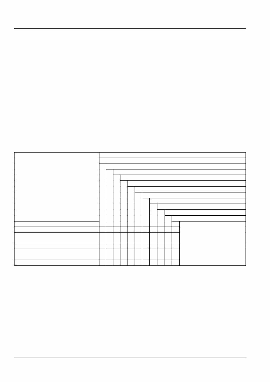
INTRODUCTION How to Use this Manual This manual is divided into Sections. Each Section is then divided into Chapters. Contents pages are included at the beginning of the manual, then inside every Section and inside every Chapter. An alphabetical Index is included at the end of a Chapter. Page number references are included for every piece of technical information listed in the Chapter Contents or Chapter Index. Each Chapter is divided into four Information types: • Technical Data (specifications) for all the mechanical, electrical or hydraulic devices, components and, assemblies. • Functional Data (how it works) for all the mechanical, electrical or hydraulic devices, components and assemblies. • Diagnostic Data (fault codes, electrical and hydraulic troubleshooting) for all the mechanical, electrical or hydraulic devices, components and assemblies. • Service data (remove disassembly, assemble, install) for all the mechanical, electrical or hydraulic devices, com- ponents and assemblies. Sections Sections are grouped according to the main functions or a systems on the machine. Each Section is identified by a letter A, B, C etc. The amount of Sections included in the manual will depend on the type and function of the machine that the manual is written for. Each Section has a Contents page listed in alphabetic/numeric order. This table illustrates which Sections could be included in a manual for a particular product. SECTION A - Distribution Systems B - Power Production C - Power Train D - Travelling E - Body and Structure F - Frame Positioning G - Tool Positioning H - Working Arm J - Tools and Couplers K - Crop Processing L - Field Processing PRODUCT Tractors X X X X X X X X Vehicles with working arms: backhoes, excavators, skid steers, ..... X X X X X X X X X Combines, forage harvesters, balers, .... X X X X X X X X X X Seeding, planting, floating, spraying equipment, .... X X X X X X X X X Mounted equipment and tools, ..... X X X X 84172758A 0 06/02/2009 4
INTRODUCTION This manual contains these Sections. The contents of each Section are explained over the following pages. Contents INTRODUCTION DISTRIBUTION SYSTEMS A POWER PRODUCTION B POWER TRAIN C TRAVELLING D BODY AND STRUCTURE E TOOL POSITIONING G CROP PROCESSING K Section Contents SECTION A, DISTRIBUTION SYSTEMS This Section covers the main systems that interact with most of the functions of the product. It includes the central parts of the hydraulic, electrical, electronic, pneumatic, lighting and grease lubrication systems. The components that are dedicated to a specific function are listed in the Chapter where all the technical information for that function is included. SECTION B, POWER PRODUCTION This Section covers all the functions related to the production of power to move the machine and to drive various devices. SECTION C, POWER TRAIN This Section covers all the functions related to the transmission of power from the engine to the axles and to internal or external devices and additional Process Drive functions. SECTION D, TRAVELLING This Section covers all the functions related to moving the machine, including tracks, wheels, steering and braking. It covers all the axles both driven axles and non-driven axles, including any axle suspension. SECTION E, BODY AND STRUCTURE This Section covers all the main functions and systems related to the structure and body of the machine. Including the frame, the shields, the operator’s cab and the platform. SECTION G, TOOL POSITIONING This Section covers all the functions related to the final and/or automatic positioning of the tool once the tool is posi- tioned using the Working Arm or the machine frame. SECTION K, CROP PROCESSING This Section covers all the functions related to crop processing. 84172758A 0 06/02/2009 5
You're Reading a Preview
What's Included?
Lifetime Access
Fast Download Speeds
Online & Offline Access
Access PDF Contents & Bookmarks
Full Search Facility
Print one or all pages of your manual
$61.99
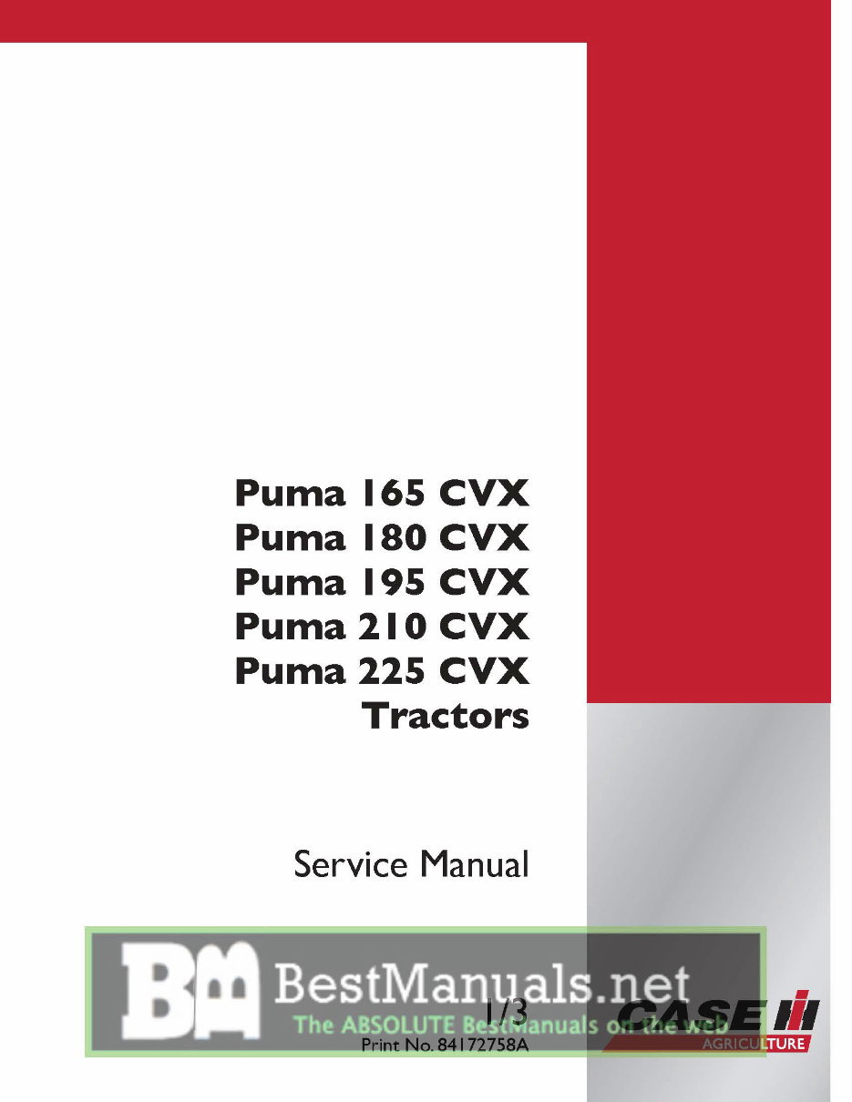
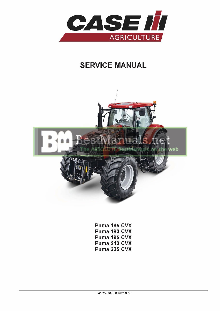
Case Puma 165 180 195 210 225 CVX Repair Service Manual - IMPROVED -
This is the COMPLETE FACTORY IH Case Puma 165, 180, 195, 210, 225 CVX Factory Service Repair Technical Manual.
IMPROVED MANUALS HAVE: Bookmarks, Searchable Text, Index and Improved Quality.
THIS MANUAL COVERS THE FOLLOWING MODELS:
165 CVX
180 CVX
195 CVX
210 CVX
225 CVX
This invaluable technical manual includes needed instructions to maintain and service your equipment using detailed diagrams and manufacturers specifications.
Navigation is simple with convenient chapter bookmarks and ability to search by keyword.
Print out entire manuals or just what you'll be working on.
* INSTANT - NO WAITING
* LANGUAGE: English
* FORMAT: .PDF
* COMPATIBLE: All Versions of Windows & Mac
* SEARCHABLE - BOOKMARKED - INDEXED
Fully Bookmarked chapters for easy navigation allowing you to identify the service repair procedures in the quickest time possible.
Detailed illustrations, exploded diagrams, drawings and photos guide you through the service repair procedures.
Completely Indexed, Bookmarked and Searchable.
CONTENTS:
INTRODUCTION
DISTRIBUTION SYSTEMS
PRIMARY HYDRAULIC POWER SYSTEM
PRIMARY HYDRAULIC POWER SYSTEM Electro-hydraulic remote valve
SECONDARY HYDRAULIC POWER SYSTEM
HYDRAULIC COMMAND SYSTEM
ELECTRICAL POWER SYSTEM
ELECTRONIC SYSTEM
FAULT CODES
PNEUMATIC SYSTEM
POWER PRODUCTION
ENGINE
FUEL AND INJECTION SYSTEM
AIR INTAKE SYSTEM
EXHAUST SYSTEM
ENGINE COOLANT SYSTEM
ENGINE COOLANT SYSTEM Fan reversing system
LUBRICATION SYSTEM
STARTING SYSTEM
POWER TRAIN TRANSMISSION
Continuously Variable Transmission (CVT)
REAR PTO Hydraulic
FRONT PTO Hydraulic
TRAVELLING
FRONT AXLE
REAR AXLE
2WD-4WD SYSTEM Hydraulic
STEERING Hydraulic
STEERING AutoPilot
SERVICE BRAKE Mechanical
SERVICE BRAKE Hydraulic
SERVICE BRAKE Pneumatic
PARKING BRAKE Mechanical
BRAKE CONNECTION Hydraulic
SUSPENSION Hydraulic
WHEELS AND TRACKS Wheels
PARKING BRAKE Electronic
BODY AND STRUCTURE
FRAME Primary frame
USER PLATFORM
ENVIRONMENT CONTROL Heating, ventilation and air-conditioning
SHIELD
WORKING ARM
HITCH Front hitch
HITCH Rear hitch
HITCH Electronic draft control
Lots of pictures, diagrams, illustrations and charts.
Technical details and step-by-step instructions you will need are included.
Additional Information: documents may require the newest version of Acrobat Reader to display correctly. Should you have any problems reading your document, please initially try upgrading to the latest version of Adobe Acrobat Reader.
We have Thousands of Manuals - email us about any you might need.
Reviews
Q&A
Recently Viewed
5,521,897Happy Clients
2,594,462eManuals
1,120,453Trusted Sellers
15Years in Business
Price:
Actual Price:
Case Puma 165 180 195 210 225 CVX Repair Service Manual - IMPROVED -









 Lifetime Access




