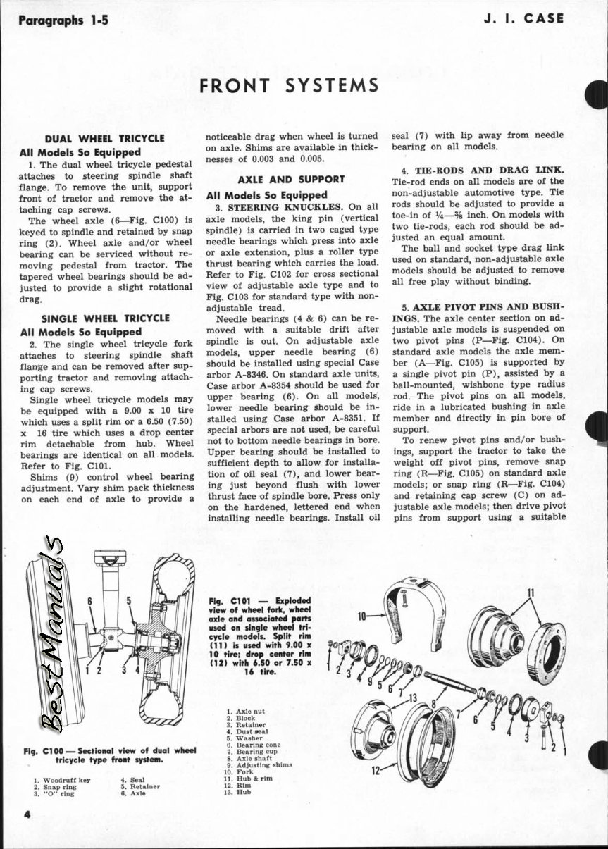
Paragraphs 1-5 J. I. CASE FRONT SYSTEMS DUAL WHEEL TRICYCLE All Models So Equipped 1. The dual wheel tricycle pedestal attaches to steering spindle shaft flange. To remove the unit, support front of tractor and remove the at- taching cap screws. The wheel axle (6—Fig. ClOO) is keyed to spindle and retained by snap ring (2). Wheel axle and/or wheel bearing can be serviced without re- moving pedestal from tractor, fhe tapered wheel bearings should be ad- justed to provide a slight rotational drag. SINGLE WHEEL TRICYCLE All Models So Equipped 2. The single wheel tricycle fork attaches to steering spindle shaft flange and can be removed after sup- porting tractor and removing attach- ing cap screws. Single wheel tricycle models may be equipped with a 9.00 x 10 tire which uses a split rim or a 6,50 (7,50) X 16 tire which uses a drop center rim detachable from hub. Wheel bearings are identical on all models. Refer to Fig, ClOl, Shims (9) control wheel bearing adjustment. Vary shim pack thickness on each end of axie to provide a noticeable drag when wheel is turned on axle. Shims are available in thick- nesses of 0.003 and 0.005, AXLE AND SUPPORT All Models So Equipped 3. STEERING KNUCKLES. On all axle models, the king pin (vertical spindle) is carried in two caged type needle bearings which press into axle or axle extension, plus a roller type thrust bearing which carries the load. Refer to Fig. C102 for cross sectional view of adjustable axle type and to Fig. C103 for standard type with non- adjustable tread. Needle bearings (4 & 6) can be re- moved with a suitable drift after spindle is out. On adjustable axle models, upper needle bearing (6) should be installed using special Case arbor A-8346. On standard axle units. Case arbor A-8354 should be used for upper bearing (6), On all models, lower needle bearing should be in- stalled using Case arbor A-8351. If special arbors are not used, be careful not to bottom needle bearings in bore. Upper bearing should be installed to sufficient depth to allow for installa- tion of oil seal (7), and lower bear- ing just beyond flush with lower thrust face of spindie bore. Press only on the hardened, lettered end when installing needle bearings. Install oil seal (7) with lip away from needle bearing on all models. 4. TIE-RODS AND DRAG LINK. Tie-rod ends on all models are of the non-adjustable automotive type. Tie rods should be adjusted to provide a toe-in of V4—% inch. On models with two tie-rods, each rod should be ad- justed an equal amount. The ball and socket type drag link used on standard, non-adjustable axle models should be adjusted to remove all free play without binding. 5, AXLE PIVOT PINS AND BUSH- INGS. The axle center section on ad- justable axle models is suspended on two pivot pins (P—Fig. C104). On standard axle modeis the axle mem- ber (A—Fig, C105) is supported by a single pivot pin (P), assisted by a ball-mounted, wishbone type radius rod. The pivot pins on all models, ride in a lubricated bushing in axie member and directly in pin bore of support. To renew pivot pins and/or bush- ings, support the tractor to take the weight off pivot pins, remove snap ring (R—Fig. C105) on standard axle models; or snap ring (R—Fig. C104) and retaining cap screw (C) on ad- justable axle models; then drive pivot pins from support using a suitable Fig. ClOe —Sectional view of dual tricycle type front system. 1. 2. 3. Woodruff key Snap ring **O" ring 4. 5. 6. Seal Retainer Axle Fi9. C101 ^ Exploded view of wheei foric, wheei axie and associated parts used on singie wheei tri- cycie modeis. Split rim (11) is used with 9.00 x 10 tire; drop center rim (12) with 6.50 or 7.50 x U tir«. 1. Axle nut 2. Block 3. Retainer 4. Dust seal 5. Washer 6. Bearing cone 7. Bearing cup 8. Axle shaft 9. Adjusting shlnia 10. Fork 11. Hub & rim 12. Rim 13. Hub 11 12
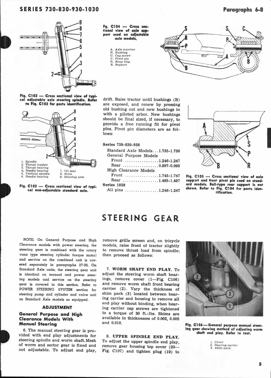
SERIES 730-830-930-1030 Paragraphs 6-8 Fig. C102 — Cross sectionai view of typf- cai adjustable axie steering spindie. Refer to Fig. C103 for parts identification. 1. spindle 2. Thrust washer 3. Thrust bearing 4. Needle bearing 5. Vertical spindle 6. Needle bearing 7. Oil seal 8. Shim 9. Steering arm Fig. C103 — Cross sectionai view of typi- cal non-ad|ustable standard axie. Fg. C104 — Cross sec- tionai view of axle sup- port used on adjustable axie modeis. A. Axle member B. Bushing C. Cap screw P. Pivot pin R. Snap ring S. Support drift. Raise tractor until bushings (B) are exposed, and renew by pressing old bushing out and new bushings in with a piloted arbor. New bushings should be final sized, if necessary, to provide a free running fit for pivot pins. Pivot pin diameters are as fol- lows: Series 730-830-930 Standard Axle Models.. .1.735-1.736 General Purpose Models Front 1.246-1.247 Rear 0.997-0.998 High Clearance Models Front 1.745-1.747 Rear 1.495-1.497 Series 1030 All pins 1.246-1.247 STEERING GEAR \ R Fig. C105 — Cross sectional view of axle support and front pivot pin used on stand- ard models. BaU-type rear support is not shown. Refer to Fig. C1(M f«>r parts iden- 1 tificatiofi. NOTE: On General Purpose and High Clearance models with power steering, the steering gear is combined with the rotary vane type steering cylinder (torque motor) and service on the combined unit is cov- ered separately in paragraphs 27-30, On Standard Axle units, the steering gear unit is identical on manual and power steer- ing models and service on the steering gear is covered in this section. Refer to POWER STEERING SYSTEM section for steering pump and cylinder and valve unit on Standard Axle models so equipped. ADJUSTMENT General Purpose and High Clearance Madels With Manual Steering 6. The manual steering gear is pro- vided with end play adjustments for steering spindle and worm shaft. Mesh of worm and sector gear is fixed and not adjustable. To adjust end play, remove grille screen and, on tricycle models, raise front of tractor slightly to remove thrust load from spindle; then proceed as follows: 7. WORM SHAFT END PLAY. To adjust the steering worm shaft bear- ings, remove cover (1—Fig. C106) and remove worm shaft front bearing carrier (2). Vary the thickness of shim pack (3) located between bear- ing carrier and housing to remove all end play without binding, when bear- ing carrier cap screws are tightened to a torque of 30 ft.-lbs. Shims are available in thicknesses of 0.003, 0.005 and 0.010. 8. UPPER SPINDLE END PLAY. To adjust the upper spindle end play, remove gear housing top cover (20— Fig. C107) and tighten plug (19) to Fig. C106 — General purpose manuol steer- ing gear showing method of cidiusting worm shoft end piay. Refer ro text. 1. Cover 2. Bearing carriei' 3. Shim pack
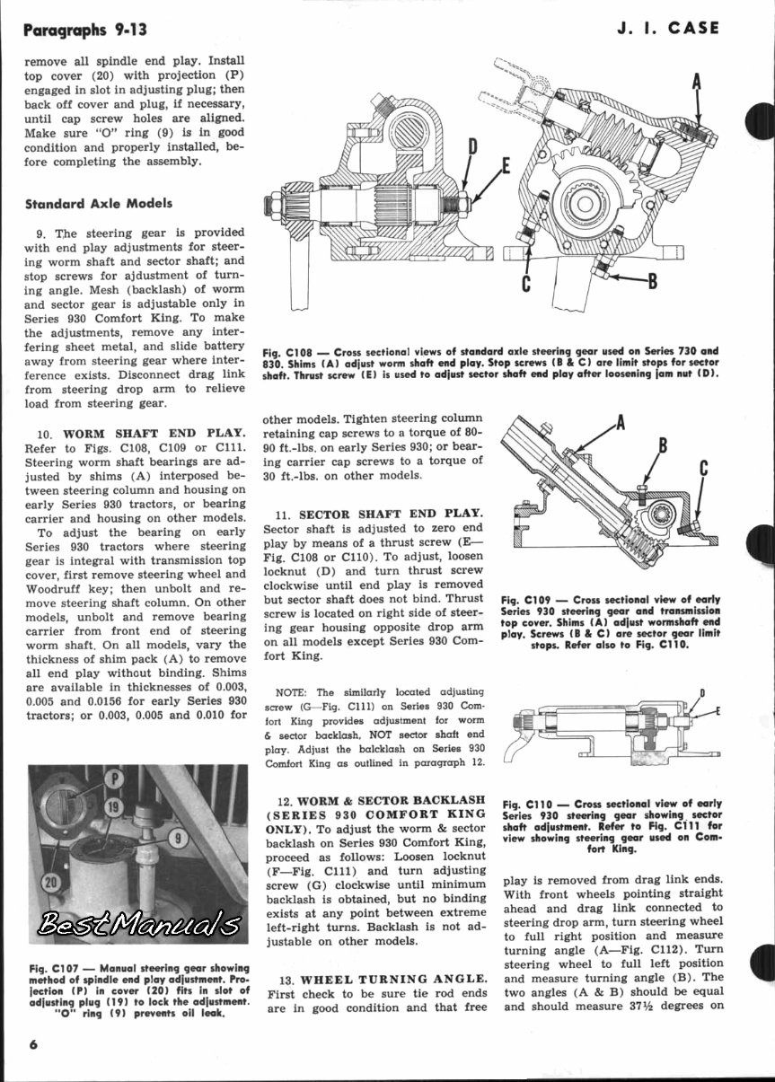
Paragraphs 9-13 J. L CASE remove all spindle end play. Install top cover (20) with projection (P) engaged in slot in adjusting plug; then back off cover and plug, if necessary, until cap screw holes are aligned. Make sure "O" ring (9) is in good condition and properly installed, be- fore completing the assembly. Standard Axle Models 9. T,he steering gear is provided with end play adjustments for steer- ing worm shaft and sector shaft; and stop screws for ajdustment of turn- ing angle. Mesh (backlash) of worm and sector gear is adjustable only in Series 930 Comfort King. To make the adjustments, remove any inter- fering sheet metal, and slide battery away from steering gear where inter- ference exists. Disconnect drag link from steering drop arm to relieve load from steering gear. 10. WORM SHAFT END PLAY. Refer to Figs. C108, C109 or Clll. Steering worm shaft bearings are ad- justed by shims (A) interposed be- tween steering column and housing on early Series 930 tractors, or bearing carrier and housing on other models. To adjust the bearing on early Series 930 tractors where steering gear is integral with transmission top cover, first remove steering wheel and Woodruff key; then unbolt and re- move steering shaft column. On other models, unbolt and remove bearing carrier from front end of steering worm shaft. On all models, vary the thickness of shim pack (A) to remove all end play without binding. Shims are available in thicknesses of 0.003, 0.005 and 0.0156 for early Series 930 tractors; or 0.003, 0.005 and 0.010 for Fig. Cl 09 — Cross sectional view of early Series 930 steering gear and transmission top cover. Shims (A) adiust wormshaft end play. Screws (B & C) are sector gear limit stops. Refer also to Fig. C1T0. Fig. C107 — Manual steering gear showing method of spindle end ploy adfustment. Pro- jection (P) in cover (20) fits in slot of adjusting plug (19) to lock the adjustment. "O" ring (9) prevents oil leak. Fig. Cl 08 Cross sectional views of standard axle steering gear used on Series 730 and 830. Shims (A) adjust worm shaft end play. Stop screws (8 & C) ore iimit stops for sector shaft. Thrust screw (E) is used to adjust sector shaft end play after loosening jam nut (D). other models. Tighten steering column retaining cap screws to a torque of 80- 90 ft.-lbs. on early Series 930; or bear- ing carrier cap screws to a torque of 30 ft.-lbs. on other models. 11. SECTOR SHAFT END PLAY. Sector shaft is adjusted to zero end play by means of a thrust screw (E— Fig. C108 or CllO). To adjust, loosen locknut (D) and turn thrust screw clockwise until end play is removed but sector shaft does not bind. Thrust screw is located on right side of steer- ing gear housing opposite drop arm on all models except Series 930 Com- fort King. NOTE: The similarly located adjusting screw (G—Fig. Clll) on Series 930 Com- fort King provides adjustment for worm & sector backlash, NOT sector shaft end play. Adjust the balcklash on Series 930 Comfort King as outlined in paragraph 12. 12. WORM & SECTOR BACKLASH (SERIES 930 COMFORT KING ONLY). To adjust the worm & sector backlash on Series 930 Comfort King, proceed as follows: Loosen locknut (F—Fig. Clll) and turn adjusting screw (G) clockwise until minimum backlash is obtained, but no binding exists at any point between extreme left-right turns. Backlash is not ad- justable on other models. 13. WHEEL TURNING ANGLE. First check to be sure tie rod ends are in good condition and that free Fig. Cl 10 — Cross sectional view of early Series 930 steering gear showing sector shaft adjustment. Refer to Fig. C111 for view showing steering gear used on Com- fort King. play is removed from drag link ends. With front wheels pointing straight ahead and drag link connected to steering drop arm, turn steering wheel to full right position and measure turning angle (A—Fig. C112). Tum steering wheel to full left position and measure turning angle (B). The two angles (A & B) should be equal and should measure 37^ degrees on
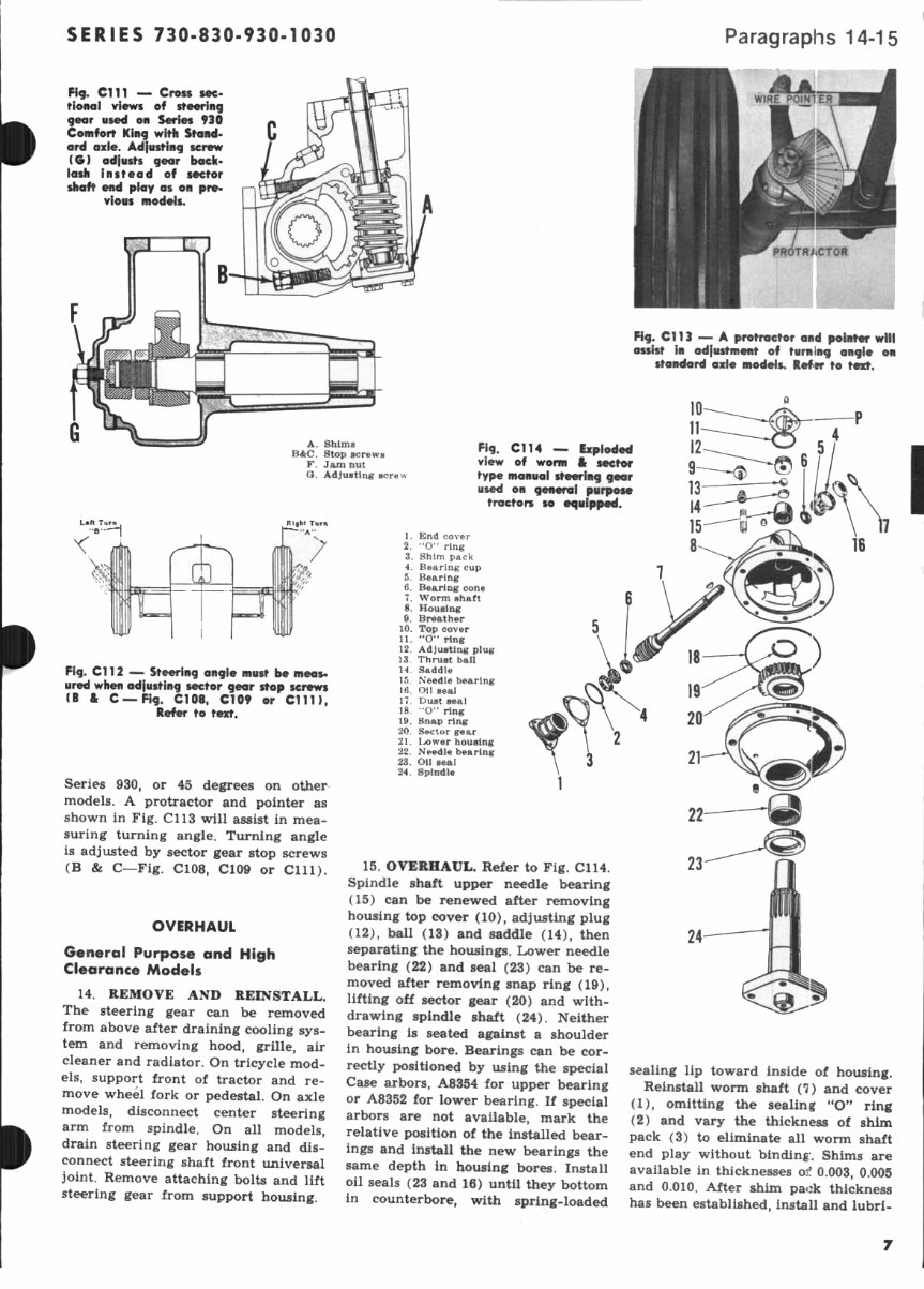
SERIES 730-830-930-1030 Paragraphs 14-15 FI9. cm ^~ Cross sec- tional views of steering gear used on Series 930 Comfort King with Stand- ord axle. Adjusting screw (G) adjusts gear back- lash instead of sector shaft end play as on i models. Fig. C113 —- A protractor and polntw will ossist in adiiistment of turning angle on standard axle models. Rof ir to A. Shims B&C. Stop BcrewB F. Jam nut O. Adjusting screw Fig. CIM ~ Exploded view of worm & sector type manual steering gear used on general purpose tractors so •quipped. • Fig. CT12 — Steering angle must be meas- ured when adjusting sector gear stop screws (B St C —Fig. C108, CT09 or Clll), Refer to text. Series 930, or 45 degrees on models. A protractor and pointer as shown in Fig. C113 will assist in mea- suring turning angle. Turning angle is adjusted by sector gear stop screws (B & C—Fig. C108, C109 or Clll). OVERHAUL General Purpose and High Clearance Models 14. REMOVE AND REINSTALL. The steering gear can be removed from above after draining cooling sys- tem and removing hood, grille, air cleaner and radiator. On tricycle mod- els, support front of tractor and re- move wheel fork or pedestal. On axle models, disconnect center steering arm from spindle. On all models, drain steering gear housing and dis- connect steering shaft front universal joint. Remove attaching bolts and lift steering gear from support housing. 1. End cover 2. "O" ring 3. Shim pack 4. Bearing cup 5. Bearing 6. Bearing cone 7. Worm shaft 8. Housing 9. Breather 10. Top cover 11. "O" ring 12. Adjusting plug 13. Thrust ball 14. Saddle 15. Needle bearing 16. Oil seal 17. Dust seal 18. '*0" ring 19. Snap ring 20. Sector gear 21. Lower housing 22. Needle bearing 23. Oil seal 24. Spindle 15. OVERHAUL. Refer to Fig. C114. Spindle shaft upper needle bearing (15) can be renewed after removing housing top cover (10), adjusting plug (12), ball (13) and saddle (14), then separating the housings. Lower needle bearing (22) and seal (23) can be re- moved after removing snap ring (19), lifting off sector gear (20) and with- drawing spindle shaft (24). Neither bearing is seated against a shoulder in housing bore. Bearings can be cor- rectly positioned by using the special Case arbors, A8354 for upper bearing or A8352 for lower bearing. If special arbors are not available, mark the relative position of the installed bear- ings and install the new bearings the same depth in housing bores. Install oil seals (23 and 16) until they bottom in counterbore, with spring-loaded sealing lip toward inside of housing. Reinstall worm shaft (7) and cover (1), omitting the sealing "O" ring (2) and vary the thickness of shim pack (3) to eliminate all worm shaft end play without binding:. Shims are available in thicknesses 03f 0.003, 0.005 and 0.010. After shim pack thickness has been established, install and lubri-
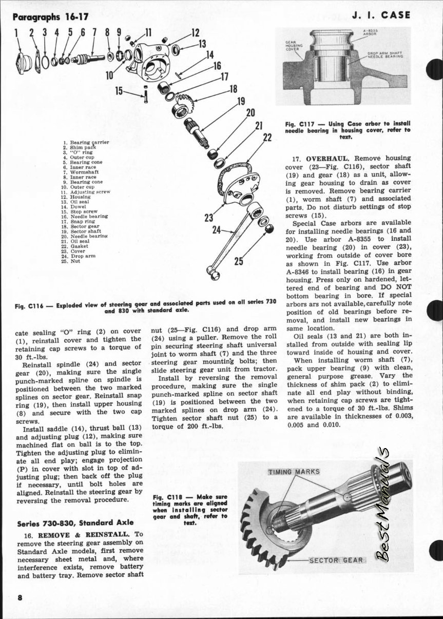
Poragraphs 16-17 1 2 3 4 5 ,6 7 J. I. CASE 1. Bearing carrier 2. Shim pacK 3. **0" ring 4. Outer cup 5. Bearing cone 6. Inner race 7. Wormshaft 8. Inner race ft. Bearing cone 10. Outer cup 11. Adjusting Hcrew 12. Housing 13. Oii seal 14. Dowel 15. Stop screw 16. Needle bearing 17. Snap ring 18. Sector gear 19. Sector shaft 20. Needie bearing 21. Oii seal 22. Gasket 23. Cover 24. Drop arm 25. Nut g C l U — Exploded view of steering gear ond Qssoclated paits used on all series 730 g. N*ii» K ^^j gj^ ^j^lj standard axle. nut (25—Fig. C116) and drop arm (24) using a puller. Remove the roll pin securing steering shaft universal joint to worm shaft (7) and the three steering gear mountin'g bolts; then slide steering gear unit from tractor. Install by reversing the removal procedure, making sure the single punch-marked spline on sector shaft (19) is positioned between the two marked splines on drop arm (24). Tighten sector shaft nut (25) to a torque of 200 ft.-lbs. cate sealing "O" ring (2) on cover (1), reinstall cover and tighten the retaining cap screws to a torque of 30 ft.-lbs. Reinstall spindle (24) and sector gear (20), making sure the single punch-marked spline on spindle is positioned between the two marked splines on sector gear. Reinstall snap ring (19), then install upper housing (8) and secure with the two cap screws. Install saddle (14), thrust ball (13) and adjusting plug (12), making sure machined flat on ball is to the top. Tighten the adjusting plug to elimin- ate all end play; engage projection (P) in cover with slot in top of ad- justing plug; then back off the plug if necessary, until bolt holes are aligned. Reinstall the steering gear by reversing the removal procedure. Series 730-830, Standard Axle 16. REMOVE & REINSTALL. To remove the steering gear assembly on Standard Axle models, first remove necessary sheet metal and, where interference exists, remove battery and battery tray. Remove sector shaft Fig. C117 — Using Cose arbor to insToll needle bearing in Housing cover, refer ro texf. 17. OVERHAUL. Remove housing cover (23—Fig. C116), sector shaft (19) and gear (18) as a unit, allow- ing gear housing to drain as cover is removed. Remove bearing carrier (1), worm shaft (7) and associated parts. Do not disturb settings of stop screws (15). Special Case arbors are available for installing needle bearings (16 and 20). Use arbor A-8355 to install needle bearing (20) in cover (23), working from outside of cover bore as shown in Fig. C117. Use arbor A-8346 to install bearing (16) in gear housing. Press only on hardened, let- tered end of bearing and DO NOT bottom bearing in bore. If special arbors ars not available, carefully note position of old bearings before re- moval, and install new bearings in same location. Oil seals (13 and 21) are both in- stalled from outside with sealing lip toward inside of housing and cover. When installing worm shaft (7), pack upper bearing (9) with clean, general purpose grease. Vary the thickness of shim pack (2) to elimi- nate all end play without binding, when retaining cap screws are tight- ened to a torque of 30 ft.-lbs. Shims are available in thicknesses of 0.003, 0.005 and 0.010. t TIMING MARKS Fig. C!18 — Make sure timing marks are aiigned when i n s t a i i i n g sector gear and shaft, refer to SECTOR GEAR 8
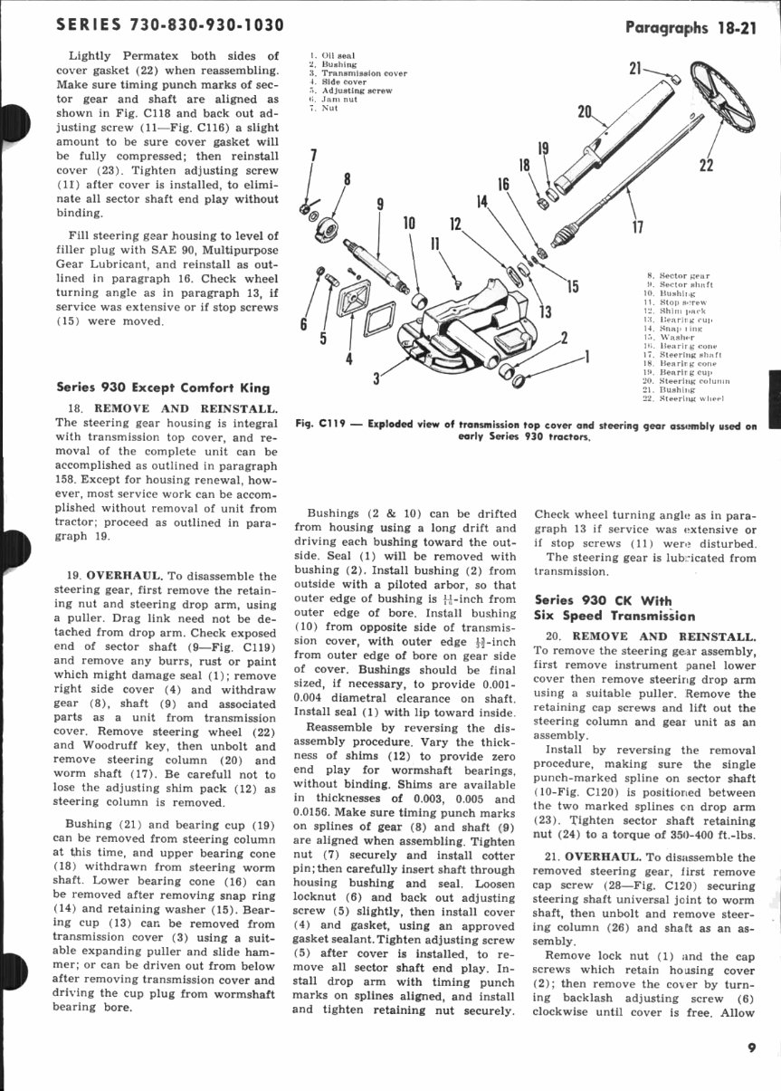
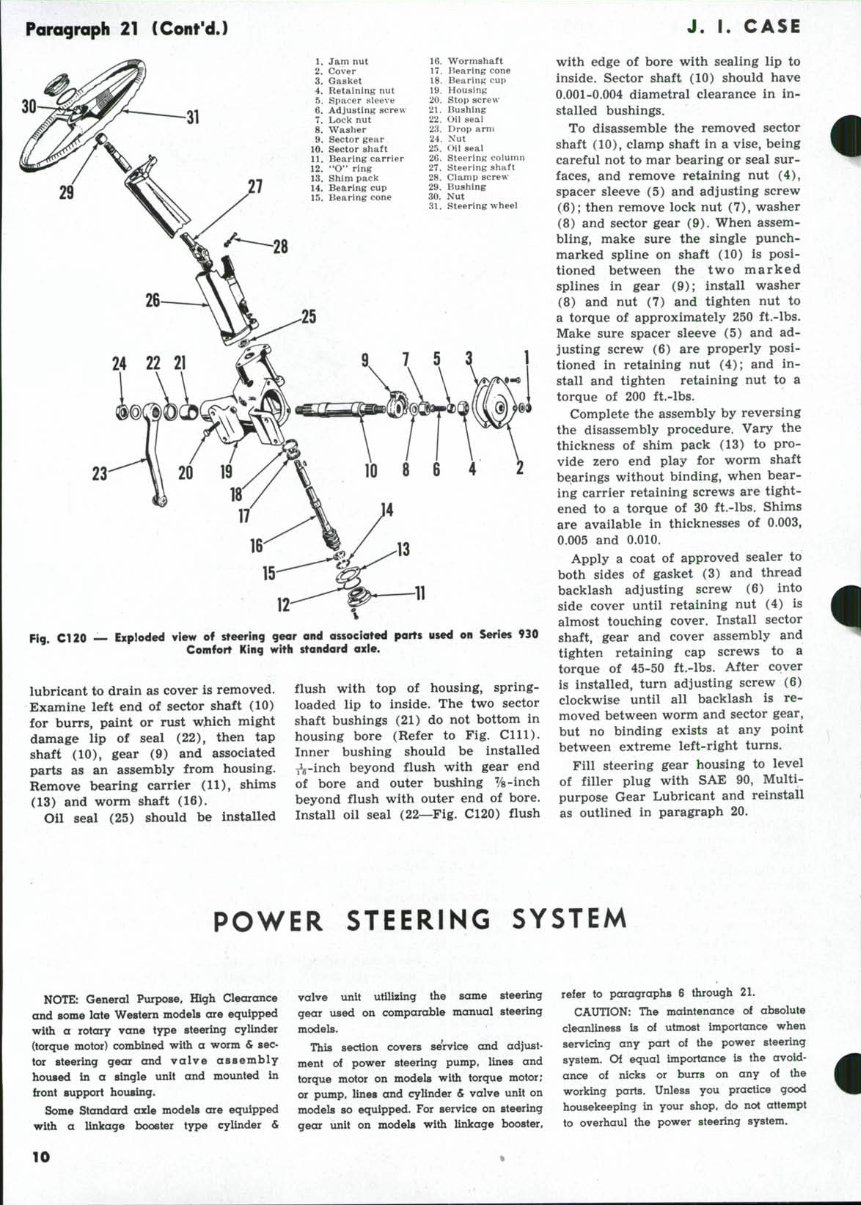
SERIES 730-830-930-1030 Paragraphs 18-21 Lightly Permatex both sides of cover gasket (22) when reassembling. Make sure timing punch marks of sec- tor gear and shaft are aligned as shown in Fig. C118 and back out ad- justing screw (11—Fig. C116) a slight amount to be sure cover gasket will be fully compressed; then reinstall cover (23). Tighten adjusting screw (11) after cover is installed, to elimi- nate all sector shaft end play without binding. Fill steering gear housing to level of filler plug with SAE 90, Multipurpose Gear Lubricant, and reinstall as out- lined in paragraph 16. Check wheel turning angle as in paragraph 13, if service was extensive or if stop screws (15) were moved. Series 930 Except Comfort King 18. REMOVE AND REINSTALL. The steering gear housing is integral with transmission top cover, and re- moval of the complete unit can be accomplished as outlined in paragraph 158. Except for housing renewal, how- ever, most service work can be accom- plished without removal of unit from tractor; proceed as outlined in para- graph 19. 19. OVERHAUL. To disassemble the steering gear, first remove the retain- ing nut and steering drop arm, using a puller. Drag link need not be de- tached from drop arm. Check exposed end of sector shaft (9—Fig. C119) and remove any burrs, rust or paint which might damage seal (1); remove right side cover (4) and withdraw gear (8), shaft (9) and associated parts as a unit from transmission cover. Remove steering wheel (22) and Woodruff key, then unbolt and remove steering column (20) and worm shaft (17). Be carefull not to lose the adjusting shim pack (12) as steering column is removed. Bushing (21) and bearing cup (19) can be removed from steering column at this time, and upper bearing cone (18) withdrawn from steering worm shaft. Lower bearing cone (16) can be removed after removing snap ring (14) and retaining washer (15). Bear- ing cup (13) can be removed from transmission cover (3) using a suit- able expanding puller and slide ham- mer; or can be driven out from below after removing transmission cover and driving the cup plug from wormshaft bearing bore. 1. Oil seal 2. Bushint; li. Transmission cover 4. Side cover ."i. Adjusting screw a. Jam nut 7. Nut 21- 8. Sector gear H. Sector shaft 10. Bushing 11. Stop screw 12. Shim pack Mi. IJearirg cup 14. Snap 1 ing 1"). Wash(ir 1(1. Bearirg cone 17. Steering shaft 18. Bearirg cone 19. Bearirg cuj) 20 Steering column 20 g 21. Bushing 22. Rteeriiy,' wheel Fig. CT19 — Exploded view of transmission top cover and steering gear assimbly used on , early Series 930 tractors. Bushings (2 & 10) can be drifted from housing using a long drift and driving each bushing toward the out- side. Seal (1) will be removed with bushing (2). Install bushing (2) from outside with a piloted arbor, so that outer edge of bushing is H-inch from outer edge of bore. Install bushing (10) from opposite side of transmis- sion cover, with outer edge ^-inch from outer edge of bore on gear side of cover. Bushings should be final sized, if necessary, to provide 0.001- 0.004 diametral clearance on shaft. Install seal (1) with lip toward inside. Reassemble by reversing the dis- assembly procedure. Vary the thick- ness of shims (12) to provide zero end play for wormshaft bearings, without binding. Shims are available in thicknesses of 0.003, 0.005 and 0.0156. Make sure timing punch marks on splines of gear (8) and shaft (9) are aligned when assembling. Tighten nut (7) securely and install cotter pin; then carefully insert shaft through housing bushing and seal. Loosen locknut (6) and back out adjusting screw (5) slightly, then install cover (4) and gasket, using an approved gasket sealant. Tighten adjusting screw (5) after cover is installed, to re- move all sector shaft end play. In- stall drop arm with timing punch marks on splines aligned, and install and tighten retaining nut securely. Check wheel turning angle as in para- graph 13 if service was extensive or if stop screws (11) were disturbed. The steering gear is lubricated from transmission. Series 930 CK With Six Speed Transmission 20. REMOVE AND REINSTALL. To remove the steering gear assembly, first remove instrument panel lower cover then remove steering drop arm using a suitable puller. ^Remove the retaining cap screws and lift out the steering column and geai unit as an assembly. Install by reversing the removal procedure, making sure t,he single punch-marked spline on sector shaft (10-Fig. C120) is positioned between the two marked splines en drop arm (23). Tighten sector shaft retaining nut (24) to a torque of 350-400 ft.-lbs. 21. OVERHAUL. To disassemble the removed steering gear, first remove cap screw (28—Fig. C120) securing steering shaft universal joint to worm shaft, then unbolt and remove steer- ing column (26) and shaft as an as- sembly. Remove lock nut (1) and the cap screws which retain housing cover (2); then remove the co\er by turn- ing backlash adjusting screw (6) clockwise until cover is free. Allow
Paragraph 21 (Cont'd.) J. I. CASE 30 1. Jam nut 2. Cover 3. Gasket 4. Retaining nut 5. Spacer sleeve 6. Adjusting screw 7. Lock nut 8. Washer 9. Sector gear 10. Sector shaft 11. Bearing carrier 12. "O" ring 13. Shim pack 14. Bearing cup 15. Bearing cone 16. Wormshaft 17. liearing cone 18. Bearing cup 19. Housing 20. Stop screw 21. Bushing 22. Oii seai 23. Drop ami 24. Nut 25. Oil seai 2G. Steering coiurnn 27. Steering shaft 28. Ciamp screw 29. Bushing 30. Nut 31. Steering wheei 23 Fig. C120 — 11 Exploded view of sfeering gear and associated parts used on Series 930 Comfort King witli standard axie. lubricant to drain as cover is removed. Examine left end of sector shaft (10) for burrs, paint or rust which might damage lip of seal (22), then tap shaft (10), gear (9) and associated parts as an assembly from housing. Remove bearing carrier (11), shims (13) and worm shaft (16). Oil seal (25) should be installed flush with top of housing, spring- loaded lip to inside. The two sector shaft bushings (21) do not bottom in housing bore (Refer to Fig, Clll). Inner bushing should be installed j^-inch beyond flush with gear end of bore and outer bushing %-inch beyond flush with outer end of bore. Install oil seal (22—Fig. C120) flush with edge of bore with sealing lip to inside. Sector shaft (10) should have 0.001-0.004 diametral clearance in in- stalled bushings. To disassemble the removed sector shaft (10), clamp shaft in a vise, being careful not to mar bearing or seal sur- faces, and remove retaining nut (4), spacer sleeve (5) and adjusting screw (6); then remove lock nut (7), washer (8) and sector gear (9). When assem- bling, make sure the single punch- marked spline on shaft (10) is posi- tioned between the two marked splines in gear (9); install washer (8) and nut (7) and tighten nut to a torque of approximately 250 ft.-lbs. Make sure spacer sleeve (5) and ad- justing screw (6) are properly posi- tioned in retaining nut (4); and in- stall and tighten retaining nut to a torque of 200 ft.-lbs. Complete the assembly by reversing the disassembly procedure. Vary the thickness of shim pack (13) to pro- vide zero end play for worm shaft bearings without binding, when bear- ing carrier retaining screws are tight- ened to a torque of 30 ft.-lbs. Shims are available in thicknesses of 0.003, 0.005 and 0.010. Apply a coat of approved sealer to both sides of gasket (3) and thread backlash adjusting screw (6) into side cover until retaining nut (4) is almost touching cover. Install sector shaft, gear and cover assembly and tighten retaining cap screws to a torque of 45-50 ft.-lbs. After cover is installed, turn adjusting screw (6) clockwise until all backlash is re- moved between worm and sector gear, but no binding exists at any point between extreme left-right turns. Fill steering gear housing to level of filler plug with SAE 90, Multi- purpose Gear Lubricant and reinstall as outlined in paragraph 20. POWER STEERING SYSTEM NOTE: General Purpose, Iftgh Clearance and aome late Western models are equipped with a rotary vane type steering cylinder (torque motor) combined with a worm & sec- tor steering gear and v a l v e assembly housed in a single unit and mounted in front support housing. Some Standard axle models are equipped with a linkage booster type cylinder & valve unit utilizing the same steering gear used on comparable manual steering models. This section covers service and adjust- ment of power steering pump, lines and torque motor on models with torque motor; or pump, lines and cylinder & valve unit on models so equipped. For service on steering gear unit on models with linkage booster. refer to paragraphs 6 through 21. CAUTION: The maintenance of absolute cleanliness is of utmost importance when servicing any part of the power steering system. Of equal importance is the avoid- ance of nicks or burrs on any of the working parts. Unless you practice good housekeeping in your shop, do not attempt to overhaul the power steering system. - 10
This comprehensive factory manual for JI Case 730, 830, and 930 Draft-O-Matic tractors provides essential instructions for maintenance, servicing, and operation. It features detailed diagrams and manufacturer specifications.
The improved manual includes bookmarks, searchable text, an index, and enhanced quality. Navigation is made simple with convenient chapter bookmarks and the ability to search by keyword. Users can print the entire manual or specific sections they are working on.
Key details:
Language: English
Format: PDF
Compatible: Win/Mac
Pages: 612
Searchable, Bookmarked, Indexed
Sections include specifications for general (engine wear limits, torque specifications), electrical specifications, wiring diagrams, diesel engine cylinder head assembly, spark ignition cylinder head assembly, engine block assemblies, water pump, spark ignition governor, gasoline carburetor, gasoline fuel shut-off (electric), gasoline fuel pump (electric), LP gas carburetor & regulator, diesel fuel injectors, Case diesel powrcel, diesel fuel injection pump adjustments timing, hydraulic cylinders, hydraulic pump, auxiliary hydraulic valve, draft-o-matic system, steering system (mechanical, hydraulic, toe-in, gear hsg., cylinders), power steering pump, transmission (brake linings, speedometer drive, differential), traction clutch, and PTO clutch.
The manual features fully bookmarked chapters for easy navigation, detailed illustrations, exploded diagrams, and drawings to guide users through service repair procedures. It also includes technical details and step-by-step instructions.
For immediate access to this manual, click the "Buy Now" button. Please note that the document may require the latest version of Acrobat Reader for proper display. If you encounter any issues, try upgrading to the latest version of Adobe Acrobat Reader.
For any additional manuals or inquiries, feel free to contact us.
Recently Viewed
5,521,897Happy Clients
2,594,462eManuals
1,120,453Trusted Sellers
15Years in Business
Price:
Actual Price:
Case 730, 830 & 930 Tractor FACTORY Service Repair Manual - IMPROVED -