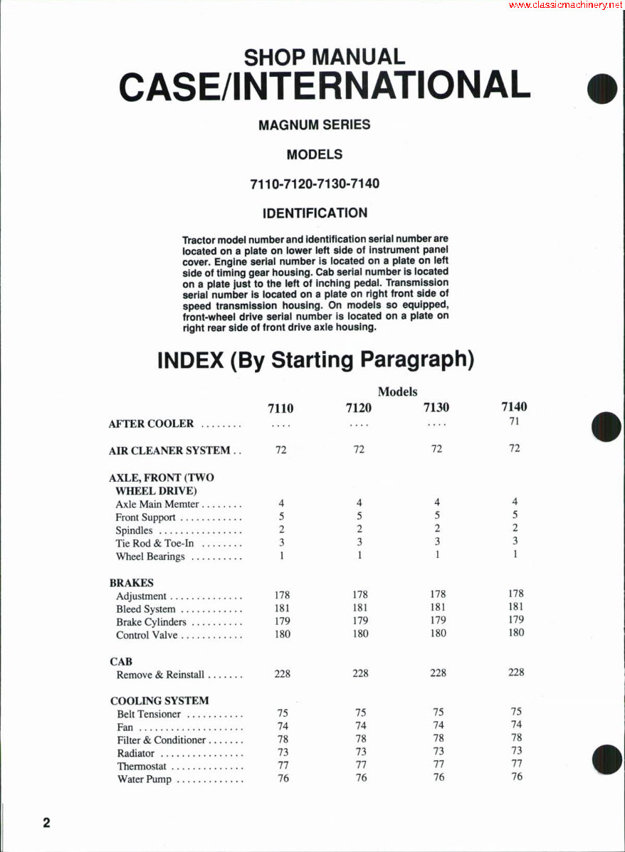
SHOP MANUAL CASE/INTERNATIONAL MAGNUM SERIES MODELS 7110-7120-7130-7140 IDENTIFICATION Tractor model number and identification seriai number are iocated on a piate on iower ieft side of instrument panei cover. Engine seriai number is iocated on a piate on left side of timing gear iiousing. Cab seriai number is iocated on a piate just to the ieft of inching pedai. Transmission seriai number is located on a piate on right front side of speed transmission housing. On modeis so equipped, front-wheei drive seriai number is iocated on a piate on right rear side of front drive axie housing. INDEX (By Starting Paragraph) AFTER COOLER AIR CLEANER SYSTEM . . 7110 72 Models 7120 7130 72 72 7140 71 72 AXLE, FRONT (TWO WHEEL DRIVE) Axle Main Memter 4 Front Support 5 Spindles 2 Tie Rod & Toe-In 3 Wheel Bearings 1 BRAKES Adjustment 178 Bleed System 181 Brake Cylinders 179 Control Valve 180 CAB Remove & Reinstall 228 COOLING SYSTEM Belt Tensioner 75 Fan 74 Filter & Conditioner 78 Radiator 73 Thermostat 77 Water Pump 76 4 5 2 3 1 178 181 179 180 4 5 2 3 1 178 181 179 180 4 5 2 3 1 178 181 179 180 228 228 228 75 74 78 73 11 76 75 74 78 73 11 76 75 74 78 73 11 76
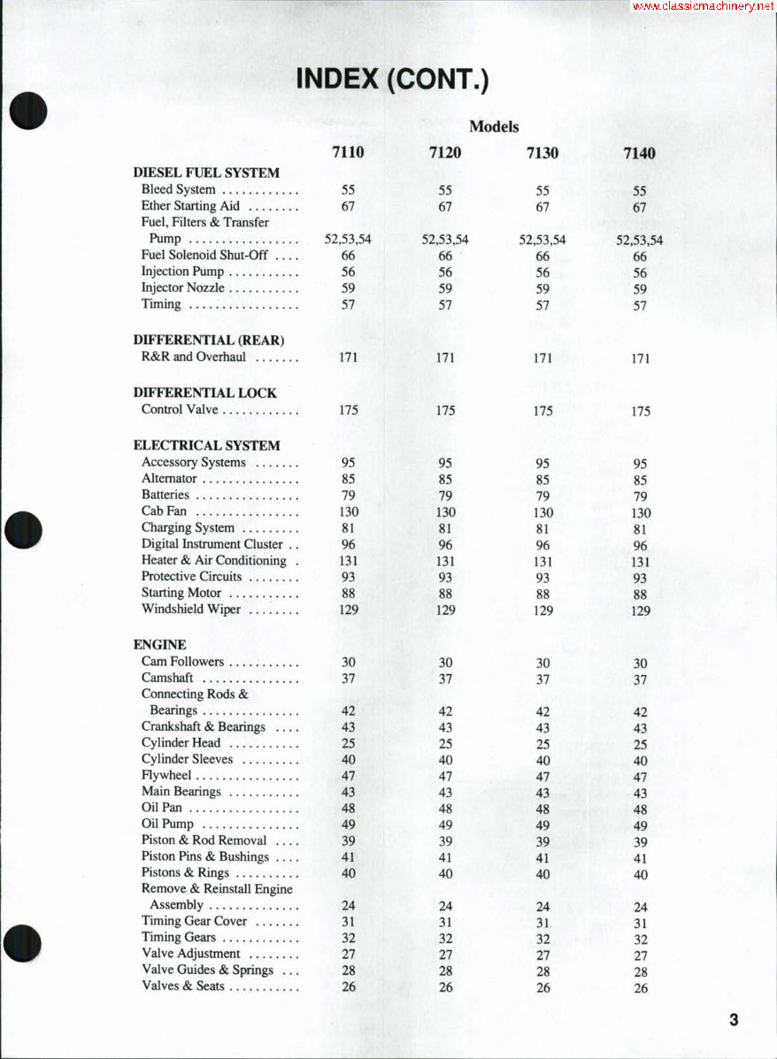
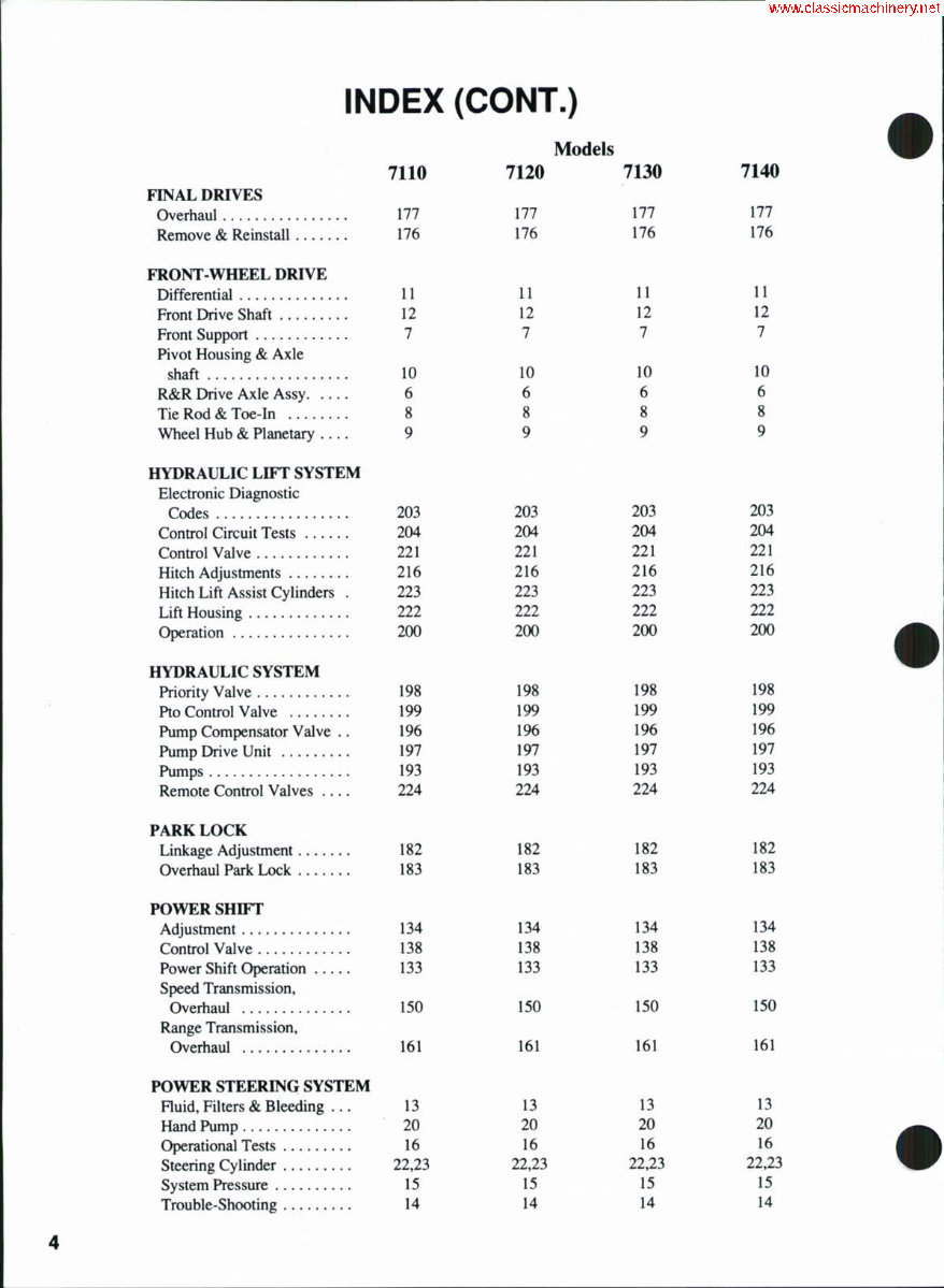
INDEX (CONT.) Models 7110 7120 7130 7140 FINAL DRIVES Overhaul 177 177 177 177 Remove & Reinstall 176 176 176 176 FRONT WHEEL DRIVE Differential 11 11 11 H Front Drive Shaft 12 12 12 12 Front Support 7 7 7 7 Pivot Housing & Axle shaft 10 10 10 10 R&R Drive Axle Assy 6 6 6 6 Tie Rod & Toe-In 8 8 8 8 Wheel Hub & Planetary .... 9 9 9 9 HYDRAULIC LIFT SYSTEM Electronic Diagnostic Codes 203 203 203 203 Control Circuit Tests 204 204 204 204 Control Valve 221 221 221 221 Hitch Adjustments 216 216 216 216 Hitch Lift Assist Cylinders . 223 223 223 223 LiftHousing 222 222 222 222 Operation 200 200 200 200 HYDRAULIC SYSTEM Priority Valve 198 1% 1% 198 Pto Control Valve 199 199 199 199 Pump Compensator Valve . . 196 196 196 196 Pump Drive Unit 197 197 197 197 Pumps 193 193 193 193 Remote Control Valves .... 224 224 224 224 PARK LOCK Linkage Adjustment 182 182 182 182 Overhaul Park Lock 183 183 183 183 POWER SHIFT Adjustment 134 134 134 134 Control Valve 138 138 138 138 Power Shift Operation 133 133 133 133 Speed Transmission, Overhaul 150 150 150 150 Range Transmission, Overhaul 161 161 161 161 POWER STEERING SYSTEM Huid, Filters & Bleeding ... 13 13 13 13 Hand Pump 20 20 20 20 Operational Tests 16 16 16 16 Steering Cylinder 22,23 22,23 22,23 22,23 System Pressure 15 15 15 15 Trouble-Shooting 14 14 14 14
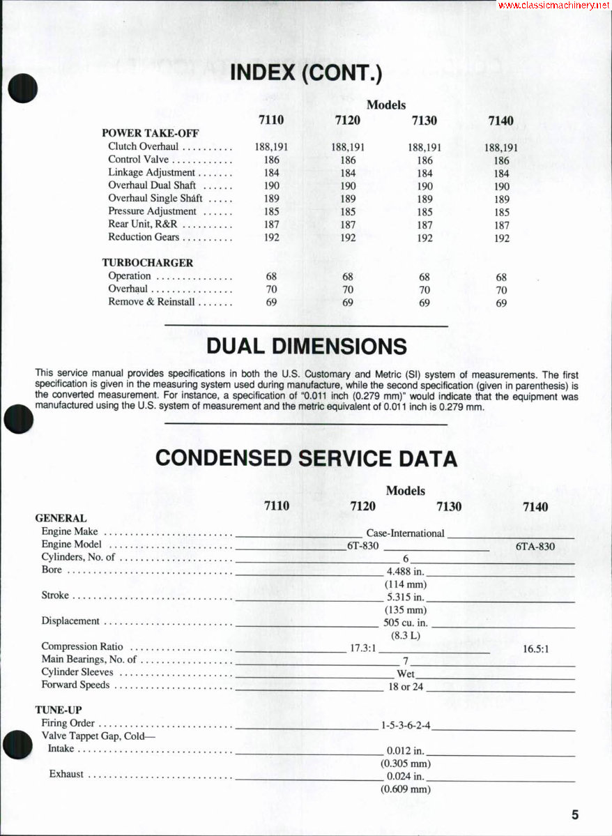
INDEX (CONT.) Models 7110 7120 7130 7140 POWER TAKE-OFF Clutch Overhaul 188,191 Control Valve 186 Linkage Adjustment 184 Overhaul Dual Shaft 190 Overhaul Single Shdft 189 Pressure Adjustment 185 Rear Unit, R&R 187 Reduction Gears 192 TURBOCHARGER Operation 68 Overhaul 70 Remove & Reinstall 69 DUAL DIMENSIONS This service manual provides specifications in both the U.S. Customary and Metric (SI) system of measurements. The first specification is given in the measuring system used during manufacture, while the second specification (given in parenthesis) is the converted measurement. For instance, a specification of "0.011 inch (0.279 mm)" would indicate that the equipment was manufactured using the U.S. system of measurement and the metric equivalent of 0.011 inch is 0.279 mm. 188,191 186 184 190 189 185 187 192 68 70 69 188,191 186 184 190 189 185 187 192 68 70 69 188,191 186 184 190 189 185 187 192 68 70 69 CONDENSED SERVICE DATA Models 7110 7120 7130 7140 GENERAL Engine Make _ ^ Case-International ^ Engine Model 6T-830 6TA-830 Cylinders, No. of 6 Bore 4.488 in. (114mm) Stroke 5.315 in. (135 mm) Displacement 505 cu. in. (8.3 L) Compression Ratio 17.3:1 16.5:1 Main Bearings, No. of 7 Cylinder Sleeves Wet Forward Speeds 18 or 24 ^___ TUNE-UP Firing Order __^^__ 1-5-3-6-2-4. Valve Tappet Gap, C o l d - Intake 0.012 in._ (0.305 mm) Exhaust 0.024 in.__ (0.609 mm)
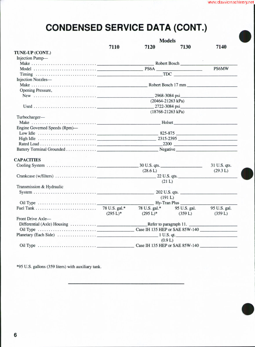
CONDENSED SERVICE DATA (CONT.) Models 7110 7120 7130 7140 TUNE-UP (CONT.) Injection Pump— Make Robert Bosch Model PS6A PS6MW Timing TDC Injection Nozzles— Make Robert Bosch 17 mm Opening Pressure, New 2968-3084 psi (20464-21263 kPa) Used 2722-3084 psi (18768-21263 kPa) Turbocharger— Make Holset Engine Governed Speeds (Rpm)— Low Idle 825-875 High Idle 2315-2395 Rated Load 2200 Battery Terminal Grounded Negative CAPACITIES Cooling System 30 U.S. qts. 31 U.S. qts. (28.6 L) (29.3 L) Crankcase (w/filters) 22 U.S. qts. (21 L) Transmission & Hydraulic System 202 U.S. qts. (191 L) Oil Type Hy-Tran Plus Fuel Tank 78 U.S. gal.* 78 U.S. gal.* 95 U.S. gal. 95 U.S. gal. (295 L)* (295 L)* (359 L) (359 L) Front Drive Axle— Differential (Axle) Housing Refer to paragraph 11. Oil Type Case IH 135 HEP or SAE 85W-140. Planetary (Each Side) 1 U.S. qt. (0.9 L) Oil Type Case IH 135 HEP or SAE 85W-140. *95 U.S. gallons (359 liters) with auxiliary tank.
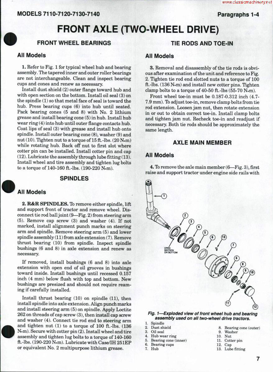
MODELS 7110-7120-7130-7140 Paragraphs 1-4 FRONT AXLE (TWO-WHEEL DRIVE) FRONT WHEEL BEARINGS TIE RODS AND TOE-IN All Models 1. Refer to Fig. 1 for typical wheel hub and bearing assembly. The tapered inner and outer roller bearings are not interchangeable. Clean and inspect bearing cups and cones and renew as necessary. Install dust shield (2) outer flange toward hub and with open section on the bottom. Install oil seal (3) on the spindle (1) so that metal face of seal is toward the hub. Press bearing cups (6) into hub until seated. Pack bearing cones (5 and 8) with No. 2 lithium grease and install bearing cone (5) in hub. Install hub wear ring (4) into hub until outer flange contacts hub. Coat lips of seal (3) with grease and install hub onto spindle. Install outer bearing cone (8), washer (9) and nut (10). Tighten nut to a torque of 15fl;.-lbs.(20 N.m) while rotating hub. Back off nut to flrst slot where cotter pin can be installed. Install cotter pin and cap (12). Lubricate the assembly through lube fitting (13). Install wheel and tire assembly and tighten lug bolts to a torque of 140-160 ft.-lbs. (190-220 N.m). SPINDLES All Models 2. R&R SPINDLES. Ib remove either spindle, lift and support front of tractor and remove wheel. Dis- connect tie rod ball joint (9—Fig. 2) from steering arm (5). Remove cap screw (3) and washer (4). If not marked, install alignment punch marks on steering arm and spindle. Remove steering arm (5) and lower spindle assembly (11) from axle extension (7). Remove thrust bearing (10) from spindle. Inspect spindle bushings (6 and 8) in axle extension and renew as necessary. If removed, install bushings (6 and 8) into axle extension with open end of oil grooves in bushings toward inside. Install bushings imtil recessed 0.157 inch (4 mm) below flush with top and bottom. New bushings are presized and should not require ream- ing if carefully installed. Install thrust bearing (10) on spindle (11), then install spindle into axle extension. Align punch marks and install steering arm (5) on spindle. Apply Loctite 262 on threads of cap screw (3), then install cap screw and washer (4). Connect tie rod end to steering arm and tighten nut (1) to a torque of 100 ft.-lbs. (136 N.m). Secure with cotter pin (2). Install wheel and tire assembly and tighten lug bolts to a torque of 140-160 ft.-lbs. (190-220 N.m). Lubricate with Case/IH 251EP or equivalent No. 2 multipurpose lithium grease. All Modeis 3. Removal and disassembly ofthe tie rods is obvi- ous after examination ofthe xmit and reference to Fig. 2. Tighten tie rod end slotted nuts to a torque of 100 ft.-lbs. (136 N.m) and install new cotter pins. Tighten clamp bolts to a torque of 40-50 ft.-lbs (55-70 N.m). Front wheel toe-in must be 0.187-0.312 inch (4.7- 7.9 mm). Ib adjust toe-in, remove clamp bolts from tie rod extension. Loosen jam nut, then rotate extension in or out to obtain correct toe-in. Install clamp bolts and tighten jam nut. Recheck toe-in and readjust if necessary. Both tie rods should be approximately the same length. AXLE MAIN MEMBER All Models 4. Tb remove the axle main member (6—Fig. 3), first raise and support tractor under engine side rails with Fig. 1—Exploded view of front wheel hub and bearing assembly used on all two-wheel drive tractors. 1. Spindle 2. Dust shield 8. Bearing cone (outer) 3. Oil seal . 9. Washer 4. Hub wear ring 10. Nut 5. Bearing cone (inner) 11. Cotter pin 6. Bearing cups 12. Cap 7. Hub 13. Lube fitting
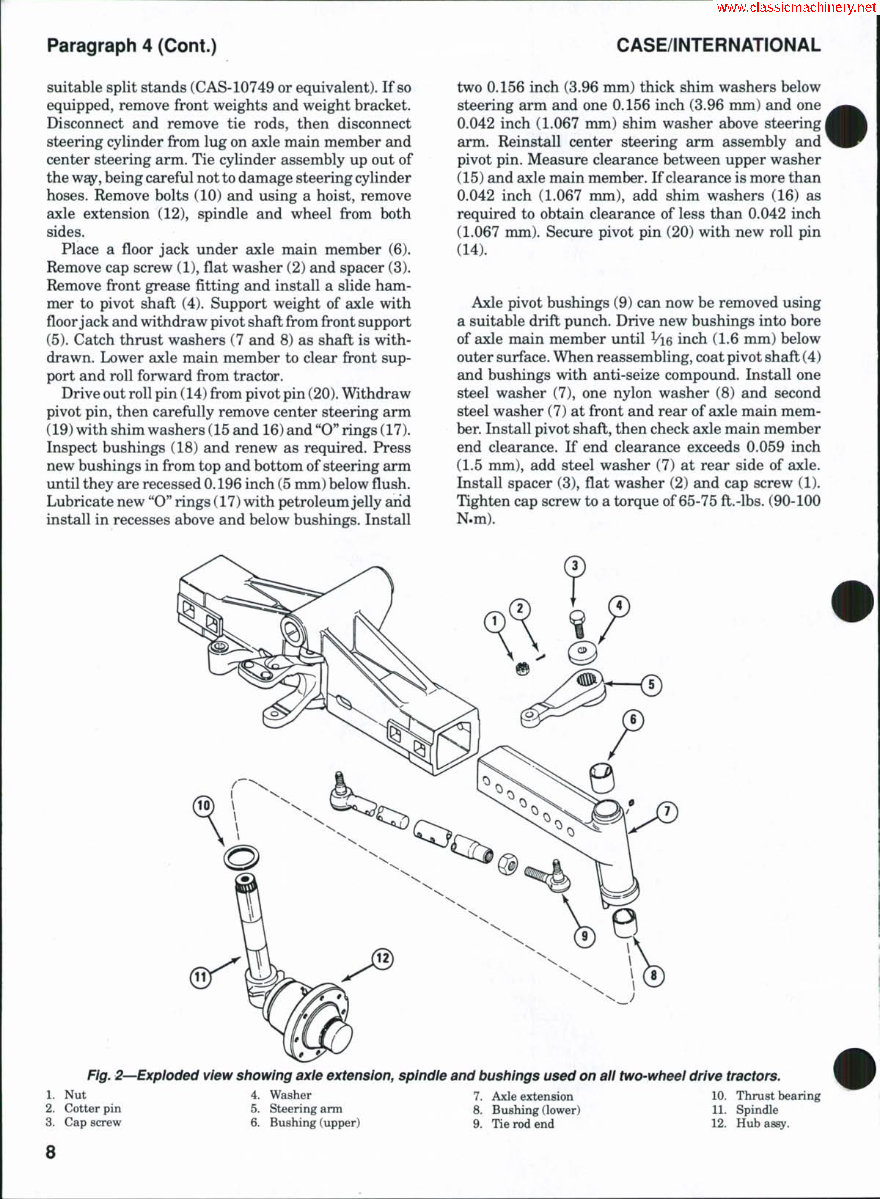
Paragraph 4 (Cont.) CASE/INTERNATIONAL suitable split stands (CAS-10749 or equivalent). If so equipped, remove front weights and weight bracket. Disconnect and remove tie rods, then disconnect steering cylinder from lug on axle main member and center steering arm. Tie cylinder assembly up out of the way, being careful not to damage steering cylinder hoses. Remove bolts (10) and using a hoist, remove axle extension (12), spindle and wheel from both sides. Place a floor jack under axle main member (6). Remove cap screw (1), flat washer (2) and spacer (3). Remove front grease fitting and install a slide ham- mer to pivot shaft (4). Support weight of axle with floor jack and withdraw pivot shaft from front support (5). Catch thrust washers (7 and 8) as shaft is with- drawn. Lower axle main member to clear fi:'ont sup- port and roll forward from tractor. Drive out roll pin (14) from pivot pin (20). Withdraw pivot pin, then carefully remove center steering arm (19) with shim washers (15 and 16) and "O" rings (17). Inspect bushings (18) and renew as required. Press new bushings in from top and bottom of steering arm until they are recessed 0.196 inch (5 mm) below flush. Lubricate new "O" rings (17) with petroleum jelly arid install in recesses above and below bushings. Install two 0.156 inch (3.96 mm) thick shim washers below steering arm and one 0.156 inch (3.96 mm) and one 0.042 inch (1.067 mm) shim washer above steering arm. Reinstall center steering arm assembly and pivot pin. Measure clearance between upper washer (15) and axle main member. If clearance is more than 0.042 inch (1.067 mm), add shim washers (16) as required to obtain clearance of less than 0.042 inch (1.067 nmi). Secure pivot pin (20) with new roll pin (14). Axle pivot bushings (9) can now be removed using a suitable drift punch. Drive new bushings into bore of axle main member until Vie inch (1.6 mm) below outer surface. When reassembling, coat pivot shaft (4) and bushings vdth anti-seize compound. Install one steel washer (7), one nylon washer (8) and second steel washer (7) at front and rear of axle main mem- ber. Install pivot shaft, then check axle main member end clearance. If end clearance exceeds 0.059 inch (1.5 mm), add steel washer (7) at rear side of axle. Install spacer (3), flat washer (2) and cap screw (1). Tighten cap screw to a torque of 65-75 ft.-lbs. (90-100 N.m). Fig, 2—Exploded view showing axie extension, spindie and bushings used on aii two-wheei drive tractors. 1. Nut 4. Washer 7. Axle extension 10. Thrust bearing 2. Cotter pin 5. Steering arm 8. Bushing (lower) 11. Spindle 3. Cap screw 6. Bushing (upper) 9. Tie rod end 12. Hub assy. 8
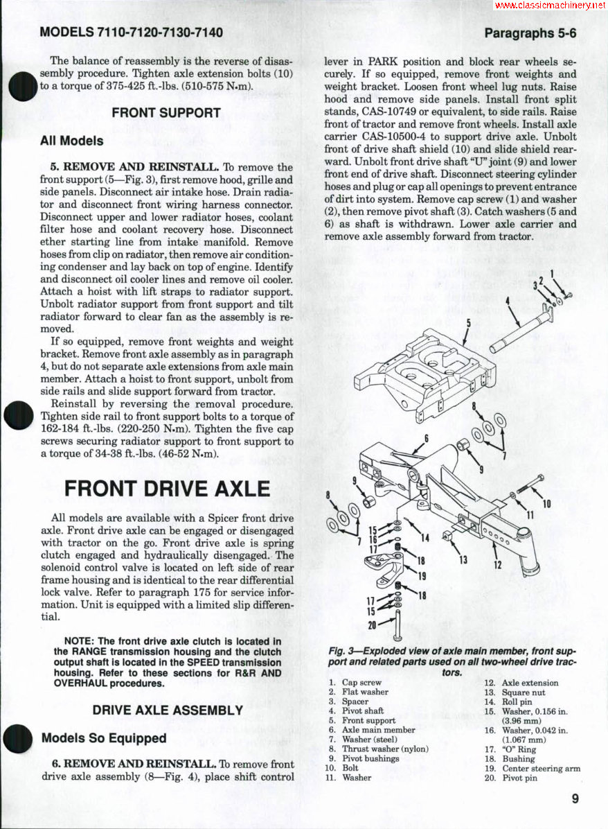
MODELS 7110-7120-7130-7140 Paragraphs 5-6 The balance of reassembly is the reverse of disas- sembly procedure. Tighten axle extension bolts (10) to a torque of 375-425 ft.-lbs. (510-575 N.m). FRONT SUPPORT All Models 5. REMOVE AND REINSTALL. Tb remove the fi-ont support (5—Fig. 3), first remove hood, grille and side panels. Disconnect air intake hose. Drain radia- tor and disconnect front wiring harness connector. Disconnect upper and lower radiator hoses, coolant filter hose and coolant recovery hose. Disconnect ether starting line from intake manifold. Remove hoses from clip on radiator, then remove air condition- ing condenser and lay back on top of engine. Identify and disconnect oil cooler lines and remove oil cooler. Attach a hoist with lift straps to radiator support. Unbolt radiator support from front support and tilt radiator forward to clear fan as the assembly is re- moved. If so equipped, remove front weights and weight bracket. Remove front axle assembly as in paragraph 4, but do not separate axle extensions from axle main member. Attach a hoist to front support, unbolt from side rails and slide support forward from tractor. Reinstall by reversing the removal procedure. Tighten side rail to front support bolts to a torque of 162-184 ft.-lbs. (220-250 N.m). Tighten the five cap screws securing radiator support to firont support to a torque of 34-38 ft.-lbs. (46-52 N.m). FRONT DRIVE AXLE All models are available with a Spicer front drive axle. Front drive axle can be engaged or disengaged with tractor on the go. Front drive axle is spring clutch engaged £ind hydraulically disengaged. The solenoid control valve is located on left side of rear frame housing and is identical to the rear differential lock valve. Refer to paragraph 175 for service infor- mation. Unit is equipped with a limited slip differen- tial. NOTE: The front drive axle clutch is located in the RANGE transmission iiousing and the ciutch output shaft is iocated in the SPEED transmission housing. Refer to these sections for R&R AND OVERHAUL procedures. DRIVE AXLE ASSEMBLY Models So Equipped 6. REMOVE AND REINSTALL. Tb remove fi-ont drive axle assembly (8—Fig. 4), place shift control lever in PARK position and block rear wheels se- curely. If so equipped, remove front weights and weight bracket. Loosen front wheel lug nuts. Raise hood and remove side panels. Install front split stands, CAS-10749 or equivalent, to side rails. Raise front of tractor and remove fi-ont wheels. Install axle carrier CAS-10500-4 to support drive axle. Unbolt front of drive shaft shield (10) and slide shield rear- ward. Unbolt front drive shaft "U" joint (9) and lower front end of drive shaft. Disconnect steering cylinder hoses and plug or cap all openings to prevent entrance of dirt into system. Remove cap screw (1) and washer (2), then remove pivot shaft (3). Catch washers (5 and 6) as shaft is withdrawn. Lower axle carrier and remove axle assembly forward from tractor. Fig. 3—Expioded view of axie main member, front sup- port and reiated parts used on aii two-wheei drive trac- tors, 1. Cap screw 12. Axle extension 2. Flat washer 13. Square nut 3. Spacer 14. Roll pin 4. Pivot shaft 15. Washer, 0.156 in. 5. Front support (3.96 mm) 6. Axle main member 16. Washer, 0.042 in. 7. Washer (steel) (1.067 mm) 8. Thrust washer (nylon) 17. "O" Ring 9. Pivot bushings 18. Bushing 10. Bolt 19. Center steering arm 11. Washer 20. Pivot pin
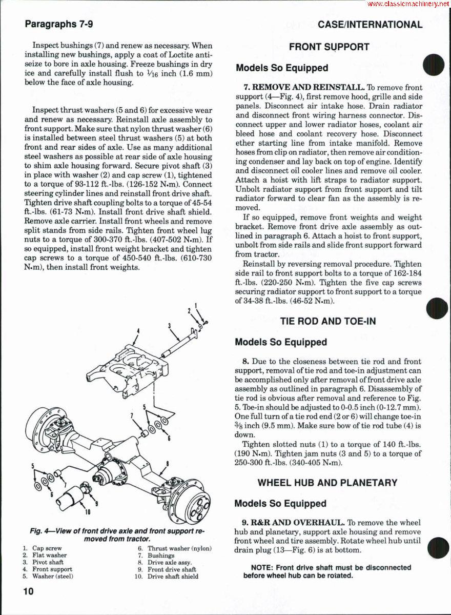
Paragraphs 7-9 CASE/INTERNATIONAL Inspect bushings (7) and renew as necessary. When installing new bushings, apply a coat of Loctite anti- seize to bore in axle housing. Freeze bushings in dry ice and carefully install flush to Vie inch (1.6 mm) below the face of axle housing. Inspect thrust washers (5 and 6) for excessive wear and renew as necessary. Reinstall axle assembly to front support. Make sure that nylon thrust washer (6) is installed between steel thrust washers (5) at both front and rear sides of axle. Use as many additional steel washers as possible at rear side of axle housing to shim axle housing forward. Secure pivot shaft (3) in place with washer (2) and cap screw (1), tightened to a torque of 93-112 ft.-lbs. (126-152 N.m). Connect steering cylinder lines and reinstall front drive shaft. Tighten drive shaft coupling bolts to a torque of 45-54 ft.-lbs. (61-73 N.m). Install fi-ont drive shaft shield. Remove axle carrier. Install front wheels and remove split standsfif-omside rails. Tighten front wheel lug nuts to a torque of 300-370 ft.-lbs. (407-502 N.m). If so equipped, install front weight bracket and tighten cap screws to a torque of 450-540 ft.-lbs. (610-730 N.m), then install front weights. Fig. 4^-View of front drive axie and front support re- moved from tractor. 1. Cap screw 2. Flat washer 3. Pivot shaft 4. Front support 5. Washer (steel) 6. Thrust washer (nylon) 7. Bushings 8. Drive axle assy. 9. Front drive shaft 10. Drive shaft shield FRONT SUPPORT Models So Equipped 7. REMOVE AND REINSTALL. Tb remove fi^ont support (4—Fig. 4), first remove hood, grille and side panels. Disconnect air intake hose. Drain radiator and disconnect front wiring harness connector. Dis- connect upper and lower radiator hoses, coolant air bleed hose and coolant recovery hose. Disconnect ether starting line from intake manifold. Remove hoses from clip on radiator, then remove air condition- ing condenser and lay back on top of engine. Identify and disconnect oil cooler lines and remove oil cooler. Attach a hoist with lift straps to radiator support. Unbolt radiator support from front support and tilt radiator forward to clear fan as the assembly is re- moved. If so equipped, remove front weights and weight bracket. Remove front drive axle assembly as out- lined in paragraph 6. Attach a hoist to front support, unbolt from side rails and slide front support forward from tractor. Reinstall by reversing removal procedure. Tighten side rail to front support bolts to a torque of 162-184 ft.-lbs. (220-250 N.m). Tighten the five cap screws securing radiator support to front support to a torque of 34-38 ft.-lbs. (46-52 N.m). TIE ROD AND TOE-iN Models So Equipped 8. Due to the closeness between tie rod and firont support, removal of tie rod and toe-in adjustment can be accomplished only after removal of front drive axle assembly as outlined in paragraph 6. Disassembly of tie rod is obvious after removal and reference to Fig. 5. Tbe-in should be adjusted to 0-0.5 inch (0-12.7 mm). One full turn of a tie rod end (2 or 6) will change toe-in % inch (9.5 mm). Make sure bow of tie rod tube (4) is down. Tighten slotted nuts (1) to a torque of 140 ft.-lbs. (190 N.m). Tighten jam nuts (3 and 5) to a torque of 250-300 ft.-lbs. (340-405 N.m). WHEEL HUB AND PLANETARY Modeis So Equipped 9. R&R AND OVERHAUL, Tb remove the wheel hub and planetary, support axle housing and remove front wheel and tire assembly. Rotate wheel hub until drain plug (13—Fig. 6) is at bottom. NOTE: Front drive shaft must be disconnected before wheei hub can be rotated. 10
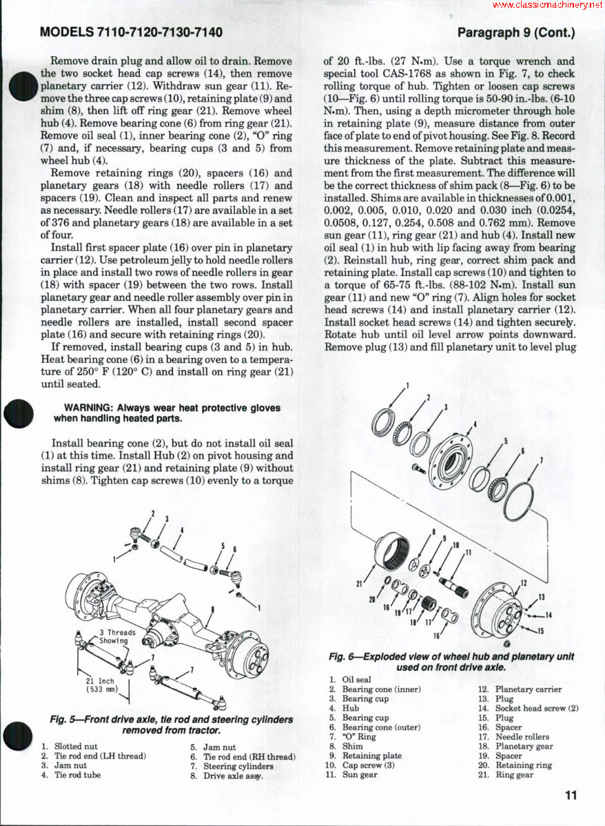
MODELS 7110-7120-7130-7140 Paragraph 9 (Cont.) Remove drain plug and allow oil to drain. Remove the two socket head cap screws (14), then remove planetary carrier (12). Withdraw sun gear (11). Re- move the three cap screws (10), retaining plate (9) and shim (8), then lift off ring gear (21). Remove wheel hub (4). Remove bearing cone (6)fii^omring gear (21). Remove oil seal (1), inner bearing cone (2), "O" ring (7) and, if necessary, bearing cups (3 and 5) from wheel hub (4). Remove retaining rings (20), spacers (16) and planetary gears (18) with needle rollers (17) and spacers (19). Clean and inspect all parts and renew as necessary. Needle rollers (17) are available in a set of 376 and planetary gears (18) are available in a set of four. Install first spacer plate (16) over pin in planetary carrier (12). Use petroleum jelly to hold needle rollers in place and install two rows of needle rollers in gear (18) with spacer (19) between the two rows. Install planetary gear and needle roller assembly over pin in planetary carrier. When all four plsmetary gears and needle rollers are installed, install second spacer plate (16) and secure with retaining rings (20). If removed, install bearing cups (3 and 5) in hub. Heat bearing cone (6) in a bearing oven to a tempera- ture of 250° F (120° C) and install on ring gear (21) until seated. WARNING: Always wear heat protective gioves when handiing heated parts. Install bearing cone (2), but do not install oil seal (1) at this time. Install Hub (2) on pivot housing and install ring gear (21) and retaining plate (9) without shims (8). Tighten cap screws (10) evenly to a torque Fig. S—Front drive axle, tie rod and steering cylinders removed from tractor. of 20 ft.-lbs. (27 N.m). Use a torque wrench and special tool CAS-1768 as shown in Fig. 7, to check rolling torque of hub. Tighten or loosen cap screws (10—Fig. 6) until rolling torque is 50-90 in.-lbs. (6-10 N.m). Then, using a depth micrometer through hole in retaining plate (9), measure distance from outer face of plate to end of pivot housing. See Fig. 8. Record this measurement. Remove retaining plate and meas- ure thickness of the plate. Subtract this measure- ment from the first measurement. The difference will be the correct thickness of shim pack (8—Fig. 6) to be installed. Shims are available in thicknesses of 0.001, 0.002, 0.005, 0.010, 0.020 and 0.030 inch (0.0254, 0.0508, 0.127, 0.254, 0.508 and 0.762 mm). Remove sun gear (11), ring gear (21) and hub (4). Install new oil seal (1) in hub with lip facing away from bearing (2). Reinstall hub, ring gear, correct shim pack and retaining plate. Install cap screws (10) and tighten to a torque of 65-75 ft.-lbs. (88-102 N.m). Install sun gear (11) and new "O" ring (7). Align holes for socket head screws (14) and install planetary carrier (12). Install socket head screws (14) and tighten secure^. Rotate hub until oil level arrow points downward. Remove plug (13) and fill planetary unit to level plug 1. Slotted nut 2. Tie rod end (LH thread) 3. Jam nut 4. Tie rod tube 5. Jam nut 6. Tie rod end (RH thread) 7. Steering cylinders 8. Drive axle ass^. Fig. &--Expioded view of wheei hub and pianetary unit used on front drive axie. 1. Oil seal 2. Bearing cone (inner) 3. Bearing cup 4. Hub 5. Bearing cup 6. Bearing cone (outer) 7. "O"Ring 8. Shim 9. Retaining plate 10. Cap screw (3) 11. Sun gear 12. Planetary carrier 13. Plug 14. Socket head screw (2) 15. Plug 16. Spacer 17. Needle rollers 18. Planetary gear 19. Spacer 20. Retaining ring 21. Ring gear 11
The repair manual for the Case IH 7120 Tractor is a valuable resource for professional technicians and do-it-yourself mechanics alike. It is designed to provide comprehensive guidance for maintaining and repairing the vehicle or engine. This manual covers a wide range of topics typically found in a factory service manual and owner's manual, offering step-by-step repair procedures, critical specifications, illustrations, maintenance, disassembly, assembly, cleaning, and reinstalling procedures.
It is suitable for individuals with basic knowledge in electrical and mechanical concepts, enabling them to make informed decisions about maintaining and repairing the Case IH 7120 Tractor. The manual is available in English and can be easily accessed on all versions of Windows and Mac, with full printable specifications and zoom capabilities.
Whether obtained in paper or digital format, the manual includes the same features, such as repair procedures, specifications, maintenance, and more. The digital version can be instantly downloaded and accessed on a computer, providing quick solutions for repairing the Case IH 7120 Tractor.
The manual covers a wide array of topics including engine removal, wiring diagrams, lubrication points, periodic maintenance, tune-up procedures, disassembly, reassembly, fuel and lubrication systems, electrical system, chassis, suspension, servicing information, tools, tightening torques, gearbox, cooling system, electrics, and much more.