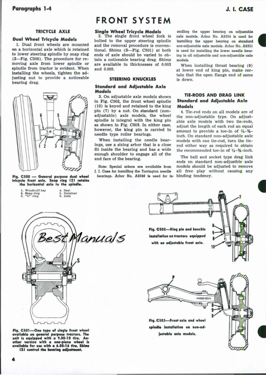
Paragraphs 1·4 TRICYCU AXlE Dual Wheel Tricycle Mod . l, 1. Dual front wheels are mounted on a horlzontaJ axle which it retained to lower steerin, ,plndle by snap ring (2.-Flg. C5(0) . The procedure fo r re- moving axle from lower spindle or splndle from tractor I, evident. When lnstallln, the wheelJ, Uchten the ad- justing nul to provide a noticeable bearing drag_ FI, . CSOO _ G..HoI ,,"'" dllGl wllM! trlcyc" fro.t ..... SRo, ,1., 121 Ntol •• tit. lIamoatol axl. to ,... .,IIMI" . 4. Seal PI,. CS01-O .. ",. of "109 1. frOll' ..... , ovolkrtll. all pweral p., ..... tntcton. T1Ie 11.1. I. ~ulppM with. ' ,00·10 tl,. , A. - othe, .......10. wl'" • a_plKe wllft, II ... , ...... for I. wltll • '.10.1' tlr.. SIII_ IS) cMtrol .. bMrI", MI ....... 4 FRONT SYSTEM Slnsle Wh •• 1 Tricycle Mod.l , 2. The single fro nt wheel fork 11 bolted to the upper steering spindle and the removal procedure 11 conven- tional. Shlnu ( S-Flg. C50l) at both ends of axle should be:! varied to ob- tain a noticeable beanne drae. Shims a~ available In thlcknesse. of 0.003 and 0.005. STEERING KNUCKLES Standard and Adjustable Axl. Models 3. On adjwtable axle model. Ihown In Fig. CM2, the front wheel I plndle (10) I. keyed and retained to the kine pin (7) by a nut. On Itandard ( non - adj us ta ble) axle models, the wheel spindle is Integra l with the kin&, pin a. Ih own in Fig. CS03. In either case, h owever, the king pin II carried in needle type roll er bearln,s. When hutalllng the needle bear- In,s, use a sizing arbor that II a close fit in.lde the bearing and has a wide enough Ihould er to engage all of the end face of th e bearing. Not.: Spedal arbors art crftlllabl. h oft!. J. I. CaM for m.tcriUnq the Torrlnqton nHdl. ~. Arbor No. A 83.t8 .. tatd. for lD· J. I. CASE ItcrlliDq lb. Up~l btorlnq em QdJUItable cnl. ft!.od .... Arbor No. A83~ .. I.IHd. for IAtlolllnq lb. UPP" bearl..Dq on standard IlOn.adJu.atcrbl. cnl. mod .... Arbor No. A83!il Ui u.ase! lor inatcrlllnq lb. lnw.r need.l. bear- lDq 1D oU odlu.ato:bll CUId non-odju.atabl. =I. mod.t.. When Installing thrwt bearing (9) at lower end of king pin, make cer- tain that the open flanie end of same Is down . TIE-RODS AND DRAG LINK Standard and Adjustable Axl. Models 4. Tie-rod ends on all models are of the non-adjustable type. On adj ust- able axle models with two ti e- rods, ad ju st the l engt h or each rod an equal amount to provide a t oe-In of 0/4-%- Inch. On standard non-adjustab le axle models with one tie-rod, turn tbe tle- rod either way as requl~d to obta in the recommended toe-In of 'I4-% -ln ch. The ball and socket type drag link ends on standard non-adjwtbl e 8lI:1e models sbould be adjusted to remove all free play without causing any binding tendency. FI,. C502-KIII' pili alld huelil. I".tellotloll 011 trac'on squlppH wltll a. adl •• tabI. frollt "I •• FI,. C50l---Ft-ollt ode atd whee, • plHIe I • .,ollotlo. o. u ... d- lutoblt> oxl' Modal l. • •
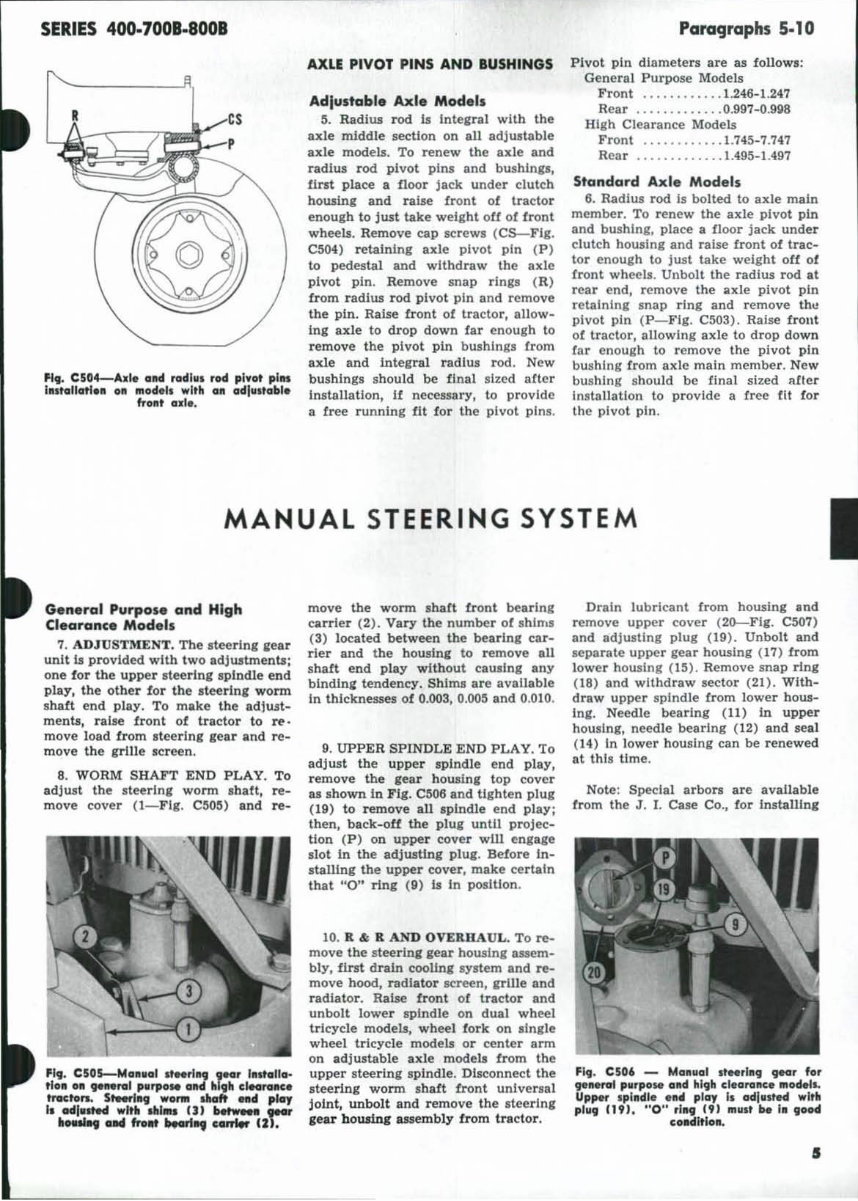
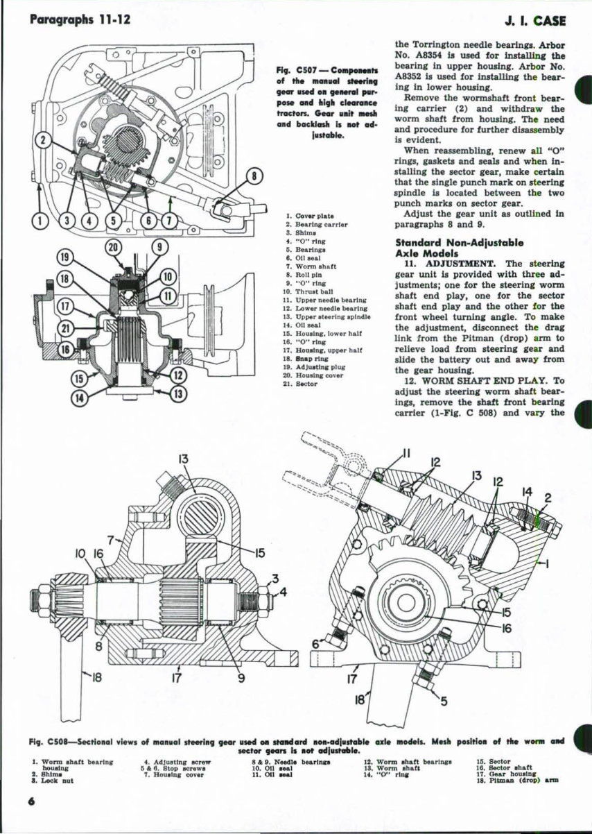
SERIES 400·7001·8001 cs ~ P ~ fI,. CS04-...... alld ,ad h. , rod piyot pllll IlIltaUolie .. all modelt _ith all Cldlil i toble frOllt 01:1 •. AXLE PIVOT PINS AND BUSHINGS Adlustable Axl. Models 5. Radius rod iJ Inte'tal with the axle middle section on all adjwtable a:de models. To renew the axle and radius rod pivot plru: and bushings, first place a floor jack under d utch housing and raise tront of tractor enough to just lake weight o[f of iront wheels . Remove cap scr ews (CS-Flg. C504) retaini ng axle pivot pin (P) to pedestal and withdraw the axle pivot pin. Remove Inap rings (R) from radius rod pivot pin and remove the pin. Raise front of tractor, allow- ing axle to drop down far enough to remove the pivot pin bushings from ax1e and Integral radius rod. New bushings s hould be final sized after Installation, if neceasary, to provide a free running fit for the pivot pins . Paragraphs 5.10 Pivot pin diameters are as follows; General PUl'pO!e Models Front .......... . . 1.246-1..247 Rear ......... . ... 0.997-0.9118 High Clearance Models Front ............ 1.745-7.747 Rear ............. 1.495-1.497 Standard Axle Models 6. Radius rod is bolted to axle main member. To renew the axle pivot pin and bushing, place a floor jack under clutch housing and raise iront of trac- tor enough to just take weIght off of Cront wheels. Unbolt the radius rod at re ar end, remove the axle pivot pin retaining snap ring and remove thu pivo t pin (P-F lg. CM3). Raise irollt of tractor, allowing axle to drop down far enough to remove the pivot pin bushing from axle main member. New bushing shou ld be final sized a lter Installation to provide a rree fit for the pivot pin . MANUAL STEERING SYSTEM General Purpose and High Clearance Models 7. ADJU STMENT. The stee r ing lear unit is provided with two adjustment. ; one for the upper stee r ing spIodle en d play, the other for the steedn, worm shaft end play . To make the adjwt- ments, raise front of tractor to re · move l oad !rom stee rlna: gear and r e- move the g rill e screen. 8. WORM SHAFT END PLAY. To adjwt the stee ring worm ah aft, re- move cover (I- Fig . CSOS) a nd re- move the worm shaft !ront bearing ca rrier (2). Vary the number of shims (3) located between the bearlng car- rier and the howing to remove all s haft end play without causing any binding tendency. Shims are available In thicknesses of 0.003, O.OOS and 0.010. 9. UPPER SPINDLE END PLAY. To adjus t the upper spi ndle eod play, remove the ,ear howin, top cover as sh own in Fig. CS06 and tighten plug ( 19) to remove all spindle end play; then, back-oft the plug until projec- tion (P) on upper cover wUl en,age slot In the adjwting plug. Belore in- stalling the upper cover, make ce rtain that "0" rIn, ( 9) is In position . 10. R &: R AND OVERHA UL. To re- move the steerlnc gear housing assem- bly, first drain cooling system and re- move hood, radiator screen, grille and radiator. Raise front of tractor and unbolt lower spindle on dual wheel tricycle models, wheel fork on ,Ingle wheel tricycle models or center arm on adjustable axle models from the upper stee r ing spindle . Disconnect the steering wonn shaft frtInt universal joint, unbolt and remove the steeri ng ,ear hoUling assembly from tra ct or. Drain lubri cant [rom housing and remove upper cover ( 20--Flg. C507) and adjusting plug (19). Unbolt and separate upper gear housing ( 17) from lower housing (I S) . Remove snap ring (18) and withdraw secto r (21). With- draw upper spi ndl e from lower how- ing . Needle bearing (11) In upper housing, needle bearing (12) and seal (14) In l ower housing can be renewed at this time. Note: Special arbors are available from the J. t. Case Co., for Installing FI9. C506 - Man ll al It .. rln9 ~r 'or ~1I.nrI pMrpo M and hl9h cl. oraM. IIIoMls. Up,., Ip1 l11dl. en4 play II odlMsted with pl1l9 (9), " 0" rl1l9 (9) IIIlIst H I. 900d co,",ltloll. 5
Para'Jraphs 11·12 4. AdJUlIU", .., .. . II .. t. 8\op IoCr ... . t. Hou , ln, CIOV.r 6 fit. C507 - C_~tI of ... _ . .. ....... .. '"' ,led ......... 1 ,.,... po .. 11M 11"11 C~ tnlcton. (No, , aJt .... aad boctlcnt. I, IIOt H- lu t _a.. 1. Co"" pl.l. 2. S..rl,.. ca r rlu S. Sblm, •. "0" n nl G. Bu.rl n .. '.011 ... 1 T. Wnrm ,hatt •• Roll pin t. "0" rllla 10. Til ...... ' ball II . Up~r n..-ll' .... rilLS 12. Lo ... rn ... I1.be .. t ..... 13. Up~r &1 ... ln, ,plndla 14. OU_I 15. " 0\1.1 .... 10 ... . hal f I t. "0" .1 ... 17. llIIual .... "pper hal( 18. 11 ..... '11 .... I '. "'J ... Un .. pI .... :0, Hou.a1q eov .. '1. s.ctor J. I. CASE the Torrln,ton needle bearln,. •. Arbor No, A8354 11 wed for 1natall.Inc the bearln, in upper howin,. Arbor No. A8352 11 used f or inltallln, the bear - • In, In lower bowln,. Remove the wormshaft front bear- in, carrier (2) and withdraw the worm . haft from howina:. The need and procedure for f urthe r diaassembly Is evident. When reauemblin,. renew all "0" riDII, .ukeb and ,eat. and when in- ltallln, the aector .ear, make certain lbat the .In,le punch mark on ,teerln, spindle fa located between the two punch mariti on sector ,ear. Adjust the ,ear unit .. outlined in paraeraphs 8 and 9. Standard Non-Adlustabl• Axl. Mod.1s 11. AD J USTMENT. The steerin, gear unit fa provided wi th tbue ad- jwtment.; one for t he steer in, W OnD. shaft end play. one for the sector shaft end play and the other for the front wheel turnin, ana:le. To make the adjustment , diaconnect the dra, link from the Pitman (drop) arm to relieve load from .teerln, ,ear and sUde the battery out and away from the ,ear housin, . 12. WORM SHAFT END PLAY. To adjust the steerina: WOnD. abaft bear- In, .. remove the shatt front bearin' • carrier (l-FI,. C ~8) and val')' the 12. W .. rm . lIdt bun .... la. W .. rm . 1I.n Iii. 8ec1.. r 18. Sector ehart IT. o.ar bouel .... U, "0" nlll II. 1'11 ... &11 (4 1'001 ._
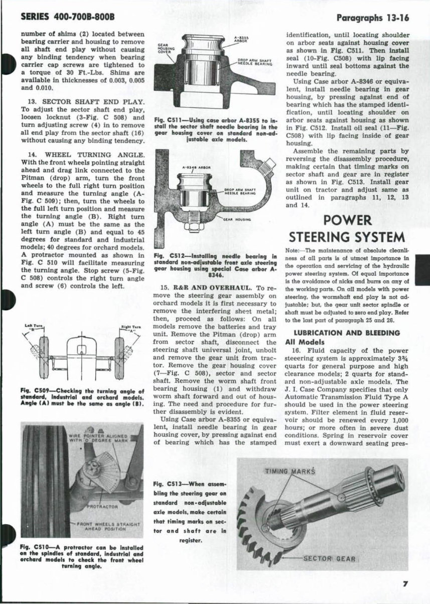
SERIES 400·7008.8008 number of ,Mini (2) located between bearine carrier and housln, to remove aU ,halt end play without eawin, any blnding tendency when beulal carrier cap lCf'ew. are t1,htened to a torque of 30 Ft.-Lbs. Shims are Rvall.ble In thicknesses of 0.003, O.OO~ and 0.010. 13. SECTOR SHAFT END PLAY. To adjust the lector shaft end play, loosen locknut (3-FI,. C 508) and tum adjustlnglcrew (4) In to remove aU end play from the sector ahaft (18) without cawing any blndJng t endency. 14. WHEEL TURNING ANGLE. With the front wheels pointing .tral,ht ahead and draa: link connected to the Pitman (drop) ann, tum the front wheell to the full right turn position and measure the turning ani le (A- Fig , C W9); then, tum the wheels to the full lett turn poIltion and measure the t urnln, angle (B). Right tum angle (A) must be the lame as the left tum angle (B) and equal to 45 degrees for standard and Industrial models; 40 degrees for orchard models . A protractor mounted as shown in Fig. C 5tO will facilitate meaaurlng th e tumlnl anile . Stop screw (5-Fi, . C !i08) controls th e rI,ht turn angle and screw (8) con trol s the lett. Fl •• C50'-Chedlll, 'he '"nlI1I9 ell,le of .tn.rd , IlMIutriol 0114 orehord mode l •. ..... 10 ( ... , mltl' be ,he WI," o. o"'lle III. fI,. C5t 0.-4 pro'rodo, Cgll be 11I1,glled •• thoe .pllldl" of Itolldord, I lId. ltrl lll olld orehgrd model. to check the froll' wh .. 1 t.nlllI, gll,lo. F19. C 511- Usl"'l cow orlt or ... · .l55 to I •• ItOIIi the wet or shcrft ..dlo becul"9 I. tk goof 11011.1., co"... o. I'o. dord lIoll-od. Intablo a id. model,. FI,. C512-11I1tct1ll1l9 _ die bearl.. III Ifolldard .o..dlntoble froot ozlo .. to.rl"'l '"' lIoul .. 11$1 .. .,.clal C_ orlt ....... Il46. 13. R&R AND OVERIIAUL. To re- move the steerln, ,ear assembly on orchard models it Is first necessary to remove the Interfering she~t metal; then, proceed as folloWl : On all models remove the batterlel and tray unit. Remove the Pitman (drop) arm from sector shaft, disconnect the steering shaft universal jOint, unbolt and remove the gear unit from trac- tor. Remove the gear housln, co ver (7- Flg. C 508), secto r and sector shaft. Remove the worm shaft tront bearing housing (1) a nd withdraw worm shalt forward and out of hous- ing. The need and procedure lor fur- ther disassembly ls evident. Usin, Case arbor A-8335 or equiva- lent, Install needle bearing in gear housing cover, by pres.sJng a,alnst end of bearing which hu the .tamped FI, . C51J-W .... ..... - Itll", the steorlltCJ geo, 011 .t ... dord IIOII -gdlvstaltle •• 10 modol., .. ak. cOffel T. ttlot tlmlll, morh all IOC' tor •• d . hgh 0'. I. NCJilter. ParaC)raphs 13·16 identification, until locatin, shoulder on arbor seats against housing cover as .hown In FI,. C511. Then lIutall seal (IG-Flg. C!i08) with lip facln, Inward until seal bottoms against the needle bearinJ:. Using Case arbor A- 834B or equiva- lent, Install needle bearing In gear housln" by pressing against end of bearing which has the stamped Identi- fication , until locating shoulder on arbor seats against housing as shown In Fig. C512. install oil seal ( ll- FI' , C!i08 ) with lip facing Inside of lear housing. Assemble the remaining parts by reversing the disassembly procedure, making certain that timing ma r ks on sector shaft and gear are In register as shown In Fig. C513. Ins tall gear unit on tractor and adjust same as outlined In paragraphs 11 , 12, 13 and 14. POWER STEERING SYSTEM Note:- The mamieDaIlClt 01 at.olulo c1ecmJl. n_ of all parts II of ulmc.'lll ImportaJlClt ill Ihe Operatloll aDd HI"fk:illq 01 Ihe bydraulk power .t .. rlnq 'plem. 01 equal importance II lhe ayoldance of n.icb cmd buns on an, of tho worklnq parts. On all model. with power .I .. rtnq, Ibll wOnMbaft end pla, • lIot ad- lulahle; but. the qear will ~or ~1Ddl. ~ uaft must be adjusted to sero.nd pkry. Refer 10 the icuot part of JXII'C9faph 2S CUld 26. LUBRICATION AND BLEEDING All Models 18. Fluid capacity of the power steeering system Is approximately 3% qua rts for ,eneral purpose and high clearance mode ls; 2 quarts f or stand- a rd non-adjus t able axle models. The J . I. Case Company specifies that only Automatic Transmission Fluid Type A .hould be used in the power steerln, system . Filter element In fluid reser- voir ahould be renewed every 1,000 houn; or more often In severe dust conditions . Sprin, In reservoir cover mu.t exert a downward seating pres- 7
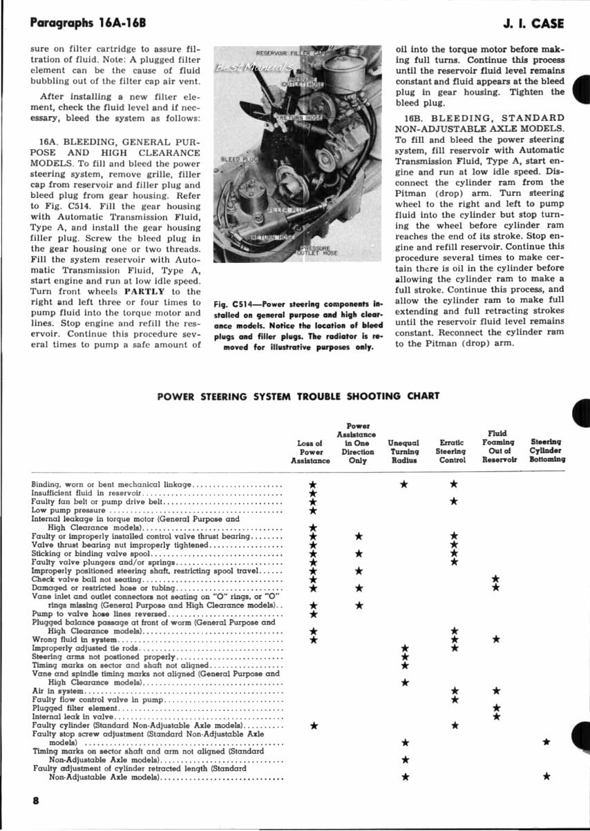
Paragraphs 16A.16B sure on filter cartridge to assure fil- trati on of fluid. Note: A pl ugged filter element can be the ca use of fluid bubbling out of th e filt er cap air vent. AIt er ilUtaUing a new fill er ele- ment, ch eck the fluid level and l! nec- essary , bleed the Iystem as foll o ws : 1 6A . BLEEDING, GENERAL PUR- POSE AND HIGH CLEA RANCE MODELS . To rill and bleed the power steering system, femove grille, filler ca p tr om reservoir and !Iller plug and bleed plug fr om gear housing. Reler to Fig , CS14. Fill the gcar housi ng with Automatic Trunsmiss ion Fluid, T ype A, and instnll the gear housi ng (Iller plug. Sc rew the bl eed plug In the "ear housi ng one or two threads. Fill the system rese rvoir wHh Auto- matic Transmission Fluid, Type A, s tart cn glne and run at low Idle speed. Turn front wheels }' ARTLY to the right and l ell three or lour times to pump riuid in to the torque mo tor and lines. Stop engine lind rcrill the r es- e rvoir. Continue this procedure scv- eral times to pump a s ale amount of Fig. C51 4-Pow..,. . , . , hl lJ compO IM.h I. - .tolled on gue rol PI"ose Gild hl Qh ,'-eI, - on' . ,"ode l •. Noti, . the loc:o,loll of bleed plulJs oltd fill..,. plugl. n. rood l o'or II No ,"oved for III l1lt ro,i .. p"rpo_ .. I, . J. I. CASE 011 into the torque motor before mak- Ing full turns. Contin ue this p rocess until the reservoir fluid lev el temalnJ constant and fluid appears at the bleed • plug In gear housing. Tight en the bleed plug . 16B. BLEEDING, STAN D ARD NON-ADJUSTABLE AXLE MODELS . To till and bleed the powe r s teering syste rp, fill reservoir with Aut omatic Transm ission Fluid, Type A, start en- gine and run at low Idle speed. Dis- connect th e cyli nder ram from the Pitman (drop) a rm. Turn st eering whee l to th e r ig ht and left to pump C1uld Into th e cyUnder but stop turn- Ing the wheel before cylinder ram reaches the end ot Its stroke. Stop en- gi ne lind refill res ervoir. Continue this procedure sever al Urnes to make cer- tain th ~ re Is 011 In the cylinder before allowi ng the cyli nder ram to make a full st roke. Continue this process, and allow the cylinder ram to make fuU ex t endi ng and full retracting st rokes until the rescrvoi r fluid level re mains constant. Reconnect the cylinder ram to the Pitman (d rop) arm . POWER STEERING SYSTEM TROUBLE SHOOTING CHART 8lndl.ng, worn or benl mechanical linkage .... , ....... , ..... ... , hauill clonl liuid In relervoir ........ , ............... , ....... ,' foully J an bel! or pump drlve belt.. , ....... , ... , ... , ... , .... , . Low pump preuur• ....................... ... , ..... , .... " .. . Inl ernal leakage In lorque malo, ( Conerol Pu~e and Higb Cl ea r ance modelt) ...... , . ... , .. " .. , .... , ......... . faulty or improperly inl;lolled c:onlfol '((Ilv. thnLIt bClaring. Valve \hnu;t b.oring nUl Improperly tightened, ..... ........... , Sticking 0' binding volv. lpooL ........................ . .... .. foulty vo ive plungerl oDdlor Ipringl .. , . . " .. " ... , .... . ..... . laIpropedy poeilioned tI.erlnq Ihaft, reltrlctlng lpool tro vel . .... . Cheek volv. boll nol _ ling .. , .. ,' .. ,' .. ,' ... , ........ ... , .. . Damaged or r .. trleted b ... or tubing , .. ,., ... , ...... . ....... . . Van. lnlel and outlet eonnec:lore not Mating on HO~ nng., or HO" rinqI miMing ( C.nerol Purpo.e and H~h Clearo:nce >nOdelt) .. Pump 10 vo)v. bo.. Un" 'ev.ned .................. .. .. _ .... . Plugged bcdonc:. pCllIOge at ir ont 01 worm (Genergj PwpoM and Hlgb Clearanc:e modela)., ...• ...... , ....... , ............ . WrODg fluid in I,..tem ................................... . Improperly ad jUi ted 11. roell ., •.. , ...... , ............ .... .... ,' St .. rlnq alllll nol pooItloned propedy ... , ...• .... •...• .. , ... , .. t1mlnq mara on Hel or aDd I boft nO! aUqned .............. , .. . Vane oDd IPlnd.l. liming mora not aUqned (G.Dero) Purpo.e and Hl9h Cl ecuaoc:e modoll) .......... , ... , ...... , .... , .... , .. Air In optem .............................................. ,' faully fl o... c:onlrol '((Ilv. in pump ..... . ........ . ....... , ... , .. Pl u99ed IUI .r ol em.nl. .................... . ... .. ..... , ... , .. . \nternalleak In volve .................................. ,' .... . foully c:yl inder (Slondard Non·AdjUil able Asle modela) . . ...... . . Faulty Il op acr .... adjUilmenl (Siandord Non·Ad jultabl. Ald. modela) ...... , ..... • .... . ...... , ...... , ........ . ... , .. , Ttmlng mara on Helor Ihalt and ann nol aligned {Slandard Non·Adj ultabl. Axle modelt) ........... .. ... . ... . ... . .... . fa ully adj Ui lmeDI 01 cylind.r relroc:ted length {Slondord Non·AdjUitable Allie modelt) .. , ... , ... " .. , ........... • , •. • Po• ., Aaa"IOoe. Lou 01 "0.. Power D ...... Aaa"lonc:e Ool, * * * * * * * * * * * * * * * * * * * * * * n.1d Uuquol Ena'" r ....... SlHrlaq TumIo. SI .. rlaq Qu . .. Cylliw:l ... Rod.lu Contr<ll R_ ",oir Iol lomlnq * * * * * * * * * * * * * * * * * * * * * * * 4 * * * * *
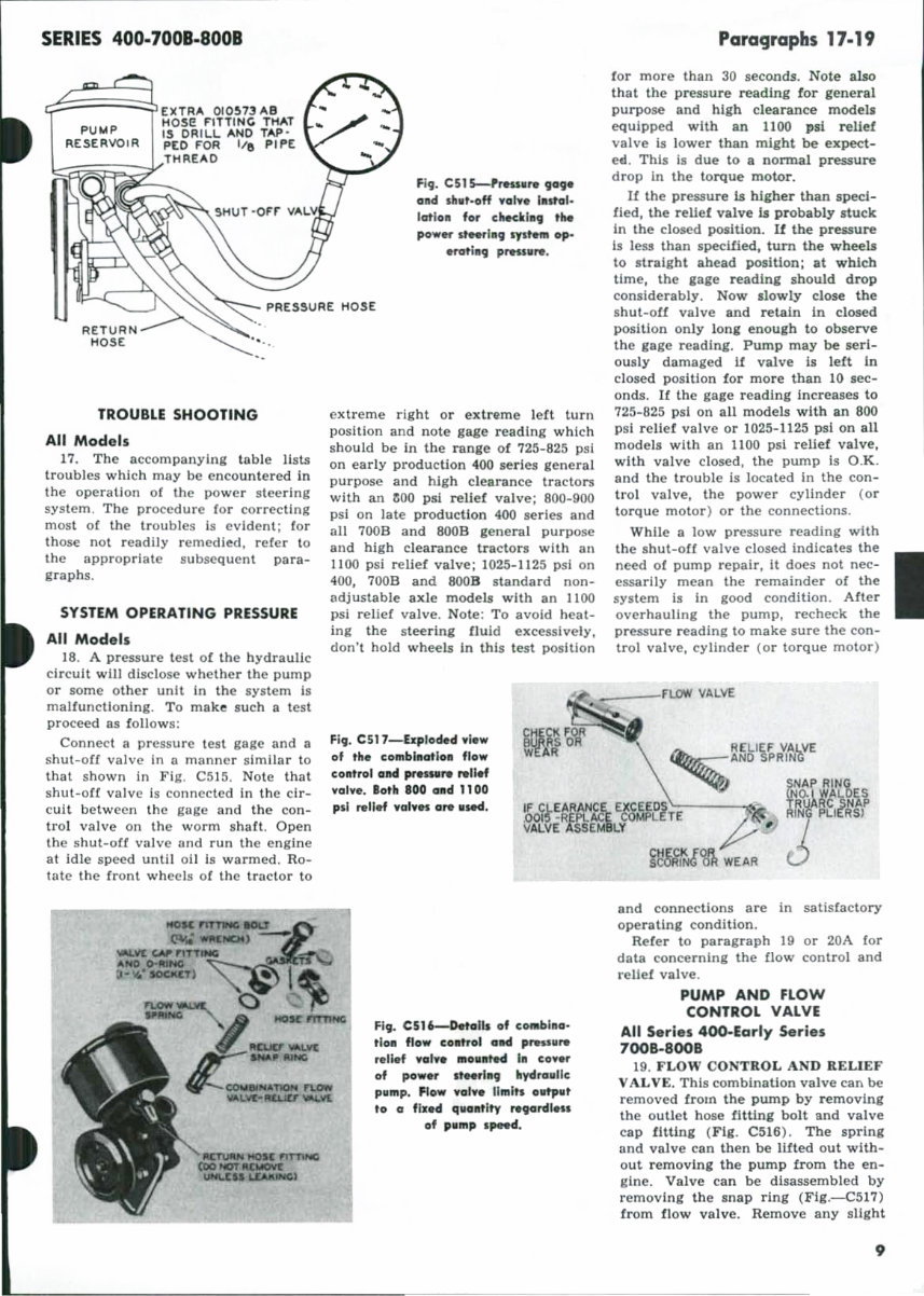
SERIES 400·7001.8001 ~:=:~~:;;1 E)(TR" OIO~73"a PUMP RESER VOI R Ho se flTT ING THAT IS DRILL AND TAP ' PED FOR l/t ~ PI roE 11~~~~~~ THRE"O Rg. C51S---het.M,. tctf4I o lld ,b t .. H yot .. Inte rl· latl.. fOf' clled.l ., tM pow ... ..,1 ., syst.. op- .rotl ., !H'"'." , PRESSURE HOSE '. TROUBLE SHOOTING All Model . 17. The accompanying table lists troubles which may be encoun tered In the operaUon of the power steering system. The procedure for co r rffting most of the troubles is evident; for those not readily rcmedil!d, refer to the appropriate subsequent par a- graphs . SYSnM OPERATING PRESSURE All Mod. r, 18. A pressure test of the hydraulic circuit will dl.sclose whether the pump or some other unit In the system I, malfunctio nin g. To make luch a tcst proceed as follow.: Connect a pressure test gage and a shut-oU valve in a manner slmlla r to that shown In Fig. c:n~. Note that shut-orr valve is connccted in the cir- cuit between the gage and t he con- tro l valve on the worm shaft. Open the sh ut-oU valve and ru n t he en gine at Idle speed until 011 Is warmed. Ro- tate the front wheels of the tractor to extreme right or extreme l eft tu rn position and note gage rea d ing wh ich shou ld be in the ra nge of 725-82~ p.sl on ea r ly pro<lucUon 400 lerles leneral p ur pose and hJgh clearance tracton with an aoo psi re lief valve; 800-900 psi on late production 400 series and all 700B and 800B general purpose and high clearance tracton with an 1100 psi relief valve; 1 025-112~ psi on 400, 700B and 800. Itandard non- adjustable ule models with an 1100 psi relief valve. Note: To avoid heat- Ing the steering fluid excessively, don't hold w heel& In this test position Fi • . CS17-lxpl oded yMi. of t he co... b'-c!tl_ flo. co lltrol ad "...,. ,.ne f Yol ..... l ot ll . 00 _4 1100 pll ,.1 1ef yolyn . .... sec! . F19. CS1 ' Oetolh of co.bl • • • ,1_ fie. co""" • ..1 "... .... ,.n.f .,..... _...... I. co_ ot po.... --'IIIJ lIyd,.. lIc p. ... p. fl ow .,. ... 1I.lts e..,..t to • fb:ed q ... lty ,...rdl n, of p. ... p ,peed. Paragraphs 17·19 fo r more than 30 seconds. Note abo that the p ressure read ing for general purpose and high clearance modell equipped with an 1100 Pit relief valve II lower tban mig ht be expect- e4 . This II due to a normal pressure drop in the torque motor. If the pressure 11 hia: ber than speci- fied, the relief valve Is probably nuck in the closed poslUon. U the pressure Is less than specWed, tum the wheell to Itnlgbt abead position; at w hich t ime, the gage readi ng moul d d rop conllderably. Now Ilow ly close the shut-oU valve and retai n In closed position only long enough to obRrve the ,age readin,. Pump may be seri- ously d amaged If valve IJ l ell In cl osed position f or more than 10 sec - onds. If the lare read ing incr eases to 725-825 p st on aU models with an 800 psi re Uef valve or 102~-1l 25 psi on an modell with an 1100 psi relief valve, w ith valve closed, the pump is O .K . and the trouble II located in the con- tro l valve, the power cylinder (o r torque motor) or the connections. WhLle a low pre58ure reading with the shut-oU valve c1O!ed indicates the need of pump repair, It docs not nec- I essarlly mean the remainder of the system Is In good condition. After overhauling the pump, recheck the pressure reading to make sure the con- trol valve, cylinder (or torque motor) ___ FLfItN VAL.VE and connections are in satisfactory operating condition. ReIe r to par agraph 19 or 20A for data concern In, the flow control and relief val ve. PUMP AND FLOW CONTROL VALVE All Serle, 4OQ-E arly Serle, 7oo&-800B 19. F LOW CO NTROL AND RE LI EF VALVE . This combination valve can be removed troll'! t he pump by removing the ouUet hose tit ting bolt and valve cap llttin, (Fig. C~16). The sp rln, and v alve can the n be lif t ed out with- out removin l t he pum p from the en- li ne. Val ve can be dI sassem bled by remov ing the sna p ri ng (FJg.-C~17 ) fro m fl ow va lve. R emove any slight 9
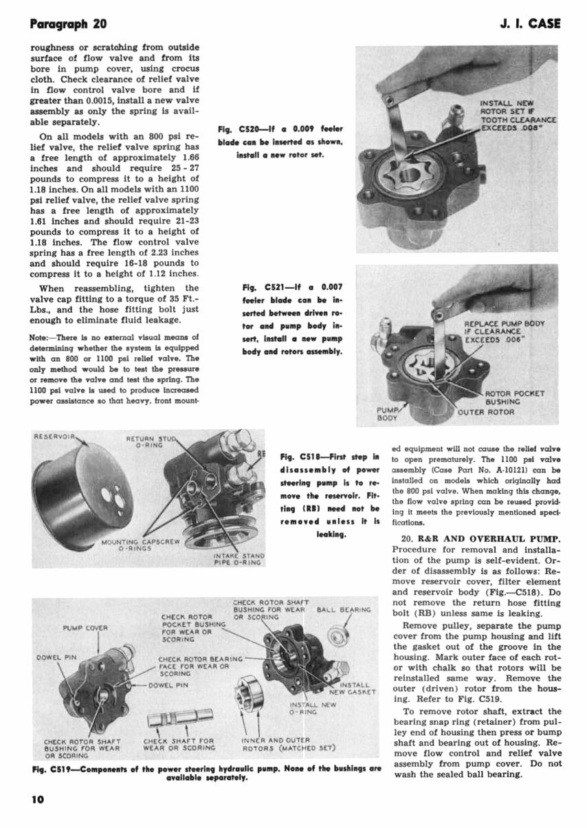
Paragraph 20 roulhn~1I or ItratchIna trom outside s urface of flow valve and from Its bore in pump cover, usln, Cl'OCWI cloth. Check clearance of relief valve In fl ow con trol valve bore and 11 &realer than 0.00 15, Install a new valve usembly u only the sprinl it avail- able separately. On all modelJ with an 800 psi re- lief valve, the rellet valve .prlng has a free length of approximately 1.66 Inches and shou ld ~uire 25 - 27 pounds to compre$l it to a height of 1.18 Inches. On all models with an 1100 psi relief valve, the relief valve spring has a free length of approximately 1.61 Inches and .hould require 21-23 pounds to compress it to 8 height of 1.18 Inches . The flow contro l valve spring h al II free length of 2.23 Inches a nd should require 16-18 pounds to compress It to a height of 1.12 inches . When reauembllng, tighten the va lve cap otting to a torque of 3~ Ft.- Lb •. , and the hoae fitting bolt just enough to eUmlnate fluid leakage. NOI.:- n'T' Is DO .KI.mol ._uol m.aJa of delermlniDq wh.ther th. a,al.m Is equ.lpped with 00 800 or 1100 pal ,oltel .01 ••. n. aaly m.thod. wouk! be 10 IH' tho pl_ur. ar ,.mo •• tho .01 •• and tHt ,b. aprlDq. n. 1100 pal .01 •• _ IIMd 10 prod.!Ke Inereoud power au_tom:e .a that h.a.-y. h onl mount· FI,. C52D--1f • O. OOt ~ bl •• c •• It. 1.wrte4 •• dlowi. l.st.1I ••• w roto, M't. FI,. C521-1f • 0.007 '"lor bl.d. C.II It. hl- Mlted betw_ d'I ..... r.- tor •• d pOlnp bMy 1.- MIt, lut.1I .... P'''P bod, .114 nt'o", _Inbl,. Fl •. C511-flnt .~ .. dh .... "'bl , 04 po_ .foetlll, ,'lnp I, t. r .... In ••• tho rMOnol,. Flt- tI .. Ill ' "" •• , be ,.In.l"" •• 1 ... It I. IMk'.,. CHeCK AOTOA ~~'" ,,-- r ... Ct rOA ~"'I'I Oft SCOI'IING >--""":L .,. CHt K SHArT rOil WtAA OR JiCORING IN .. tA "'1010 OU'tl'I AO"Oll.s ( ...... 'dttD .seT) '1,. csn-e.mp .... ,.. .f tho po •• r ,fNrl., hydr.ullc p.... p. Non •• f ,ho t .... hlll, . .... ••• lIobl ... por .... I, . • 0 J. I. CASE ocI equlpmont wW not OOUM tho ,oUel .01 •• 10 ~n p"mO'turol,. Th. 1100 ,. 1 1'oJl'. ClH.mhly (Co .. Part No. A·10121 ) oon be IMtolied on mod.le which odglna lly had the BOO p.1 1' 0'11". Whon making this chang •. Ihe now 1'0'11'0 .p.ing can be rollMd pro.ki- Ing It mHtII Ih o p ••• Io ... ly montloned. apeel· liculiolll. 20. R&R AND OVE RII AUL PUMP. Procedure for removal and Installa- tion of th e pump is sell-evident . Or- der of dlus.aembly Is as fallaws : Re- mave reservalr cover, ll1ter element and reservoir body (Flg.-C~1 8 ). Do not remave the return hase littlng bolt ( HB ) unless ume Is leaki ng . Remove pulley, separate the pump cover from the pump howlng and lUt the gasket out of the groove io the housIng. Mark outer face of each rot- or with chalk 10 that rotors will be reinstalled same way . Remove the outer (driven) rotar fram the hous- Ing. Reier to Fig. C519. • TO' remave rotar shalt, extract the bearing snap ring ( retainer) from pul- • ley end of housing then press ar bump s haft and bearing out of bowing. Re- move flaW control and relief valve assembly lrom pump cover. Do not wash the sealed ball bearIng .
You're Reading a Preview
What's Included?
Lifetime Access
Fast Download Speeds
Online & Offline Access
Access PDF Contents & Bookmarks
Full Search Facility
Print one or all pages of your manual
$46.99
Case 701B, 703B, 711B, 713B Tractor Workshop Service Repair Manual -
This is a comprehensive workshop service repair manual for the Case 701B, 703B, 711B, and 713B tractors. It contains essential instructions, detailed diagrams, and manufacturer specifications for maintaining and servicing your tractor.
Whether you are a professional mechanic or a DIY enthusiast, this manual provides simple navigation with chapter bookmarks and keyword search functionality. You can easily print the entire manual or specific sections relevant to your work.
The manual is instantly accessible and compatible with all versions of Windows and Mac. It is searchable, bookmarked, and indexed for quick reference. You'll find comprehensive illustrations, exploded diagrams, drawings, and photos to guide you through the service repair procedures.
Topics covered in this manual include belt pulley, brake system, carburetor, "Case-O-Matic" system, clutch, cooling system, diesel fuel system, differential, electrical system, engine, final drives, front system, hydraulic lift system, ignition & electrical system, LP-gas system, power steering system, power take-off, transmission, and more.
With numerous pictures, diagrams, illustrations, and charts, this manual is perfect for tune-ups, regular maintenance, and repairs. It includes mechanical details and step-by-step instructions to meet your needs.
If you are looking for a reliable resource to troubleshoot and maintain your Case tractors, this workshop service repair manual is an invaluable tool.
INSTANT - NO WAITING
LANGUAGE: English
FORMAT: PDF
COMPATIBLE: All Versions of Windows & Mac
SEARCHABLE - BOOKMARKED - INDEXED
For immediate access to this manual, click the green & white "NOW" button at the top right-hand side of this page. If you require other manuals, feel free to email me for assistance.
Reviews
Q&A
Recently Viewed
5,521,897Happy Clients
2,594,462eManuals
1,120,453Trusted Sellers
15Years in Business
Price:
Actual Price:
Case 701B, 703B, 711B, 713B Tractor Workshop Service Repair Manual -