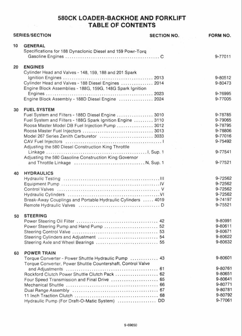
580CK LOADER-BACKHOE AND FORKLIFT TABLE OF CONTENTS SERIES/SECTION SECTION NO . 10 GENERAL Specifications tor 188 Dynaclonic Diesel and 159 Powr-Torq Gasoline Engines .......................................... C 20 ENGINES Cylinder Head and Valves . 148.159. I88 and 201 Spark Ignition Engines ......................................... 2013 . Cylinder Head and Valves 188 Diesel Engines ............... 2014 Engine Block Assemblies . l88G. lS9G. 148G Spark ignition Engines ................................................ 2023 . Engine Block Assembly 1880 Diesel Engine ............... 2024 30 FUEL SYSTEM Fuel System and Filters . 188D Diesel Engine ................ 3010 Fuel System and Filters . 188G Spark Ignition Engine ......... 3110 Roosa Master Model DB Fuel Injection Pump ................ 301 2 Roosa Master Fuel Injectors ................................ 3013 Model 267 Series Zenith Carburetor ........................ 3033 CAV Fuel Injectors .......................................... I Adjusting the 580 Diesel Construction King Throttle Linkage ........................................... I. Sup . 1 Adjusting the 580 Gasoline Construction King Governor and Throttle Linkage ................................ N. Sup . 1 40 HYDRAULICS Hydraulic Testing .......................................... 111 Equipment Pump ........................................... IV Control Valves .............................................. V Hydraulic Cylinders ........................................ VI ..... Break-Away Couplings and Portable Hydraulic Cylinders 4019 Remote Hydraulic Valves .................................... D 50 STEERING Power Steering Oil Fitter .................................... 42 Power Steering Pump and Hand Pump ........................ 52 Steering Control Valve ....................................... 53 Steering Cylinders and Adjustment .......................... 54 Steering Axle and Wheel Bearings ........................... 55 60 POWER TRAIN Torque Converter . Power Shuttle Hydraulic Pump ............ 43 Torque Converter. Power Shuttle Countershaft. Control Valve ......................................... and Adjustments 61 Rockford Clutch Power Shuttle Clutch Pack ................... 62 Four Speed Transmission and Final Drive ..................... 65 .......................................... Mechanical Shuttle 66 ....................................... Dual Range Assembly 67 11 Inch Traction Clutch ..................................... 68 Hydraulic Pump (For Draft-O-Matic System) ................. DD
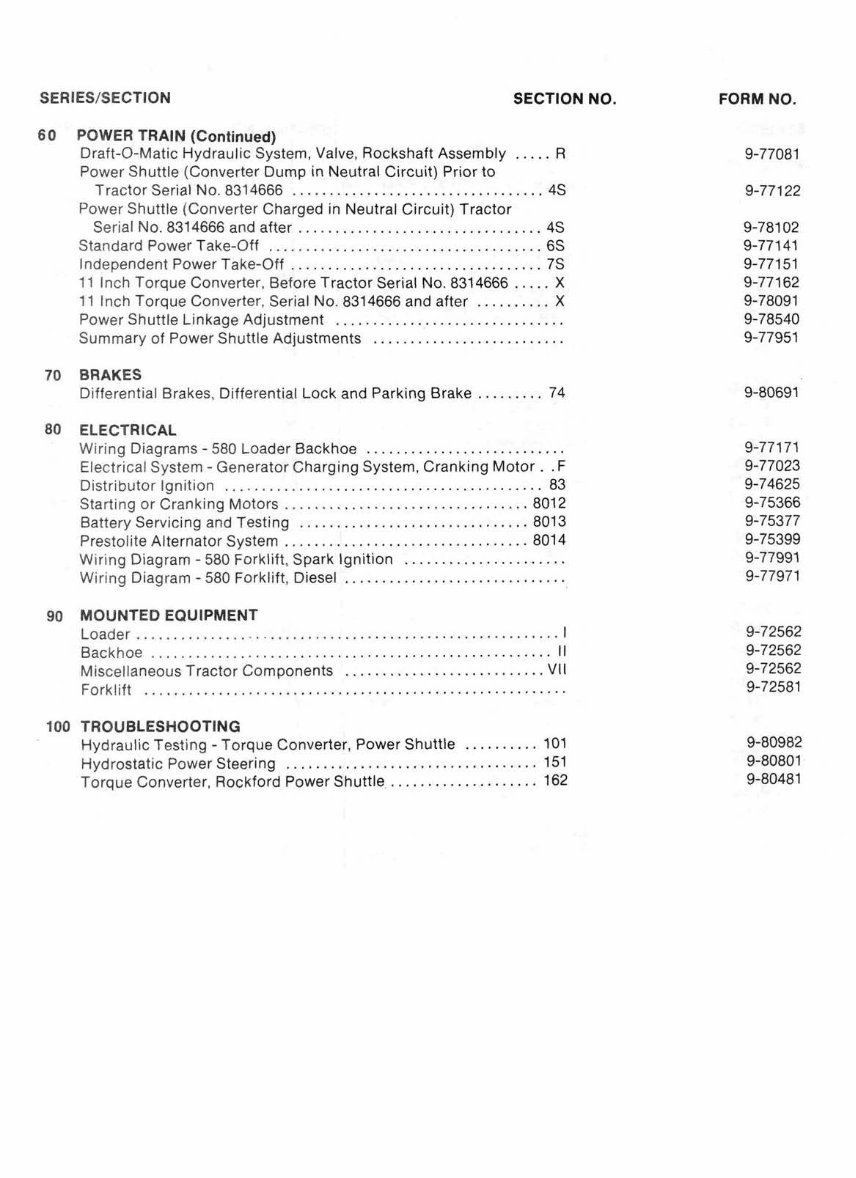
SERIES/SECTION SECTION NO . 60 POWER TRAIN (Continued) Draft-0-Matic Hydraulic System. Valve. Rockshaft Assembly ..... R Power Shuttle (Converter Dump in Neutral Circuit) Prior to Tractor Serial No . 8314666 ................................. 4s Power Shuttle (Converter Charged in Neutral Circuit) Tractor Serial No . 8314666 and after ................................ 4s Standard Power Take-Off .................................... 6s Independent Power Take-Off ................................. 7s 11 Inch Torque Converter. Before Tractor Serial No . 8314666 ..... X 11 Inch Torque Converter. Serial No . 8314666 and after .......... X Power Shuttle Linkage Adjustment .............................. Summary of Power Shuttle Adjustments ......................... 70 BRAKES Differential Brakes. Differential Lock and Parking Brake ......... 74 80 ELECTRICAL Wiring Diagrams . 580 Loader Backhoe ........................... Electrical System . Generator Charging System. Cranking Motor . . F Distributor Ignition ........................................... 83 Starting or Cranking Motors ................................ 8012 Battery Servicing and Testing .............................. 8013 Prestolite Alternator System ................................ 8014 Wiring Diagram . 580 Forklift. Spark Ignition ..................... Wiring Diagram . 580 Forklift. Diesel ............................. 90 MOUNTED EQUIPMENT ......................................................... Loader I ...................................................... Backhoe 11 ........................... Miscellaneous Tractor Components VII ......................................................... Forklift Hydraulic Testing . Torque Converter. Power Shuttle ......... 101 .................................. Hydrostatic Power Steering 151 .................... Torque Converter. Rockford Power Shuttle 162 FORM NO . 9-77081 9-771 22
Roc. Form 9-77011 Section C
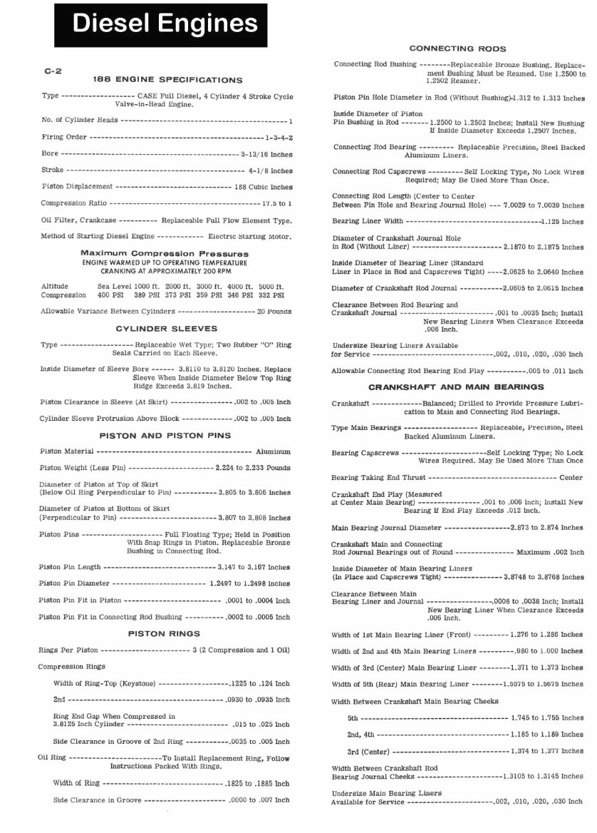
CONNECTING RODS c-2 188 ENGINE SPECIFICATIONS Type------------------- CASE Full Diesel, 4 Cylinder 4 Stroke Cycle Valve-in-Head Engine. Connecting Rod Bushing -------- Replaceable Bronze Bushing. Replace- ment Bushing Must be Reamed. Use 1.2500 to 1.2502 Reamer. Piston Pin Hole Diameter in Rod (Without Bushing)-1.312 to 1.313 Inches Stroke .--------------------------------------------- 4-1/8 Inches Connecting Rod Capscrews --------- Self Locking Type, No Lock Wires Connecting Rod Length (Center to Center Compression Ratio ----------------------- ---------------- 17.5 to 1 Between Pin Hole and Bearing Journal Hole) --- 7.0029 to 7.0039 Inches Oil Filter, Crankcase ---------- Replaceable Full Flow Element Type. Bearing Liner width ------- 1.125 Inches Method of Starting Diesel Engine ------------ Electric fatarting Motor. Diameter of Crankshaft Journal Hole m Rod (Without Lmer) ---------------------2.1870 to 2.1875 Inches Maximum compression Pressures ENGINE WARMED UP TO OPERATING TEMPERATURE Inside Diameter of Bearing Liner (Standard CRANKING AT APPROXIMATELY 200 RPM Liner in Place in Rod and Capscrews Tight) ----2.0625 to 2.0640 Inches Altitude Sea Level 1000 ft. 2000 it. 3000 ft. 4000 ft. 5000 ft. Diameter of Crankshaft Rod Journal ----------- 2.0605 to 2.0615 Inches Compression 400 PSI 389 PSI 373 PSI 359 PSI 346 PSI 332 PSI Clearance Between Rod Bearing and Allowable Variance Between Cylinders .................... 2U Pounds Crankshaft ~ o ~ ------------------------ .001 to .0035 Inch; Install New Bearing Liners When Clearance Exceeds CYLINDER SLEEVES .006 Inch. Type ------------------- Replaceable Wet Type; Two Rubber "0" Ring Undersize Bearing Liners Available Seals Carried on Each Sleeve. for service------------------------------- .002, .010, .020, .030 Inch Inside Diameter of Sleeve Bore ------ 3.8110 to 3.8120 Inches. Replace Allowable Connecting Rod Bearing End Play ---------- .005 to .011 Inch Sleeve When Inside Diameter Below Top Ring Ridge Exceeds 3.819 Inches. CRANKSHAFT AND MAIN BEARINGS Piston Clearance in Sleeve (At Skirt) ---------------- .UU2 to .OU5 Inch Crankshaft -------------Balanced; Drilled to Provide Pressure Lubri- cation to Main and Connecting Rod Bearings. Cylinder Sleeve Protrusion Above Block ------------- .002 to .U05 Inch Type ~ai ~~arin ----------------- -- Replaceable, Precision, Steel PISTON AND PISTON PINS Backed Aluminum Liners. Piston Weight (Less Pin) -----Ñ---ÑÑ--- 2.224 to 2.233 Pounds Diameter of Piston at Top of Skirt (Below Oil Ring Perpendicular to Pin) ----------- 3.805 to 3.806 Inches Diameter of Piston at Bottom of Skirt (Perpendicular to Pm) ------------------------- 3.807 to 3.808 Inches Piston Pins -------------------Full Floating Type; Held in Position With Snap Rings in Piston. Replaceable Bronze Bushing in Connecting Rod. Piston Pm Diameter ------------------------ 1.2497 to 1.2498 Inches Bearing Capscrews ----------------------Self Locking Type; No Lock Wires Required. May Be Used More Than Once Crankshaft End Play (Measured at Center Main Bearing) ---------------- .001 to .006 Inch; Install New Bearing It End Play Exceeds .U12 Inch. Main Bearing Journal Diameter -----------------2.873 to 2.874 Inches Crankshaft Main and Connecting Rod Journal Bearings out of Round --------------- Maximum .002 Inch Inside Diameter of Main Bearing Liners (In Place and Capscrews Tight) --------------- 3.8748 to 3.8768 Inches Clearance Between Main Piston Pin Fit in Piston ......................... .0001 to .0004 Inch Bearm Liner and Journal -----------------.0008 to .OD38 Inch: Install Piston Pin Fit in Connecting Rod Bushing ---------- .0002 to .0005 Inch New Bearing Liner When Clearance Exceeds .006 Inch. PISTON RINGS Width of 1st Main Bearing Liner (Front) --------- 1.276 to 1.286 Inches ~ing Per piston ....................... 3 (2 Compression and 1 Oil) Width of 2nd and 4th Main Bearing Liners ---------.980 to 1.000 Inches compression Rings Width of 3rd (Center) Main Bearing Liner ------~1.371 to 1.373 Inches Width of Ring-Top (Keystone) ------------------ .I225 to .124 Inch Width of 5th (Rear) Main Bearing Liner ~ ~ ~ 1 . 5 to 1.5675 Inches Ring End Gap When Compressed in 5th -----ÑÑÑÑÑ------ÑÑ- 1.745 to 1.755 Inches 3.8125 Inch Cylinder --- ....................... .015 to .025 Inch Znd, 4th Ñ---ÑÑÑÑÑ 1,185 to 1.189 Inches Side Clearance in Groove of 2nd Ring -----------.0035 to .005 Inch 3rd (Center) ÑÑÑÑÑ----- 1.374 to 1.377 Inches Oil Ring ------------------------TO Install Replacement Ring, Follow Instructions Packed With Rings. Width Between Crankshaft Rod Bearing Journal Cheeks ----------------------1.310 to 1.3145 Inches Width of Ring -- ------------- ------------"--- A825 to .I885 Inch Undersize Main Bearing Liners Side Clearance m Groove ÑÑÑ---Ñ .0000 to .007 Inch Available for Service ----------------------.002, '010, .020, .030 Inch
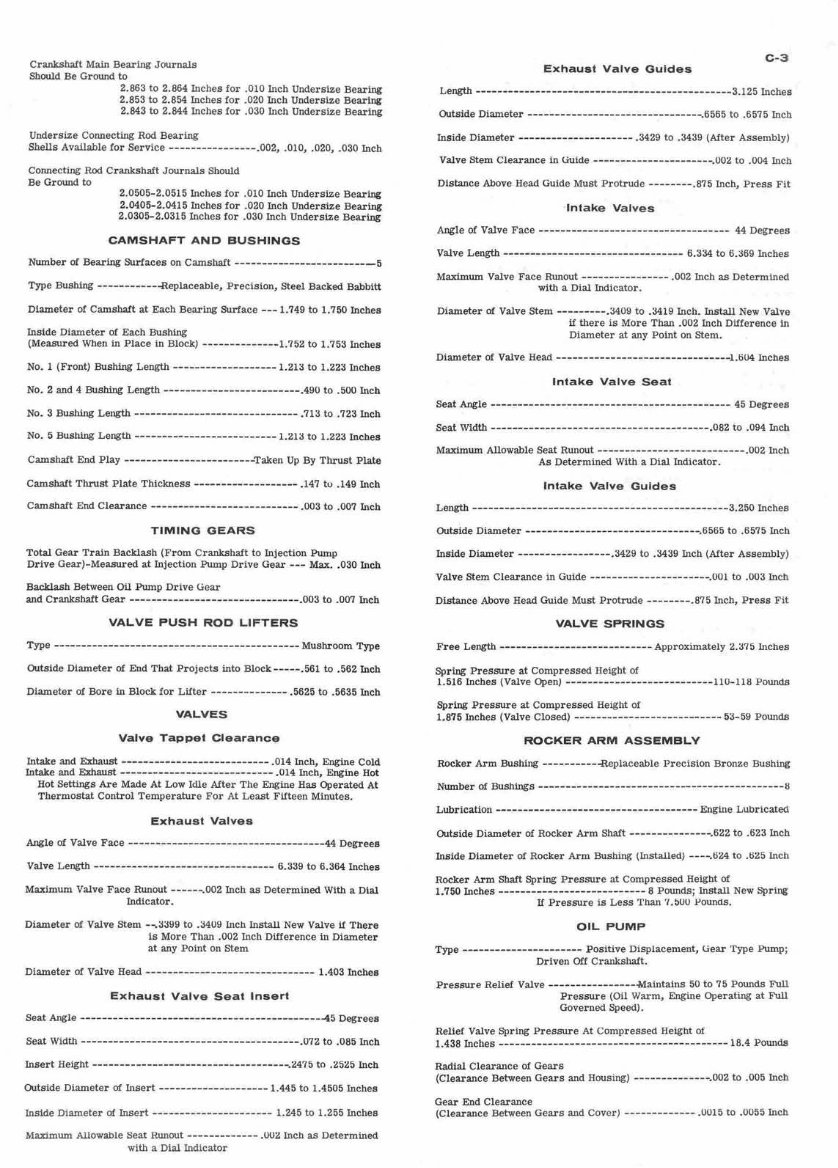
Crankshaft Main Bearing Journals Should Be Ground to 2.863 to 2.864 Inches for .010 Inch Undersize Bearing 2.853 to 2.854 Inches for .020 Inch Undersize Bearing 2.843 to 2.844 Inches for .030 Inch Undersue Bearing Undersize Connecting Rod Bearing Shells Available for Service ---------------- .002, .010, .020, .030 Inch Connecting Rod Crankshaft Journals Should Be Ground to 2.0505-2.0515 Inches for .010 Inch Undersize Bearing 2.0405-2.0415 Inches for .020 Inch Undersize Bearing 2.0305-2.0315 Inches for .030 Inch Undersize Bearing Type Bushing ----------- -Replaceable, Precision, Steel Backed Babbitt Diameter of Camshaft at Each Bearing Surface --- 1.749 to 1.750 Inches Inside Diameter of Each Bushing (Measured When in Place m Block) -------------- 1.752 to 1.753 Inches No. 1 (Front) Bushing Length ---------------- 1.213 to 1.223 Inches NO. 2 and 4 Bushing Length ------ ------------- .490 to .500 Inch No. 5 Bushing Length --------- -------- ------ 1.213 to 1.223 Inches Camshaft End Play ----------------------Taken Up By Thrust Plate Camshaft Thrust Plate Thickness ------------------- .I47 tu .I49 Inch Camshaft End Clearance ---------------------- ----- -003 to .007 Inch TIMING GEARS Total Gear Train Backlash (From Crankshaft to Injection Pump Drive Gear)-Measured at Injection Pump Drive Gear --- Max. .030 Inch Backlash Between Oil Pump Drive Gear and Crankshaft Gear ------------- -003 to .007 Inch VALVE PUSH ROD LIFTERS Type --Ñ-----Ñ----------------ÑÑ-----------ÑMus Type Outside Diameter of End That Projects into Block-----.561 to .562 Inch Diameter of Bore in Block for Lifter -------------- .5625 to 3635 Inch VALVES Valve Tappet Clearance Intake and Exhaust ---ÑÑÑÑÑÑ--- Inch, Engine Cold Intake and Exhaust---------------------------- .014 Inch, Engine Hot Hot Settings Are Made At Low Idle After The Engine Has Operated At Thermostat Control Temperature For At Least Fifteen Minutes. Valve Length ------------------------------- 6.339 to 6.364 Inches Maximum Valve Face RunOut ------.002 Inch as Determined With a Dial Indicator. Diameter of Valve Stem --.3399 to A409 Inch Install New Valve it There is More Than .002 Inch Difference in Diameter at any Point on Stem Exhaust Valve Seat Insert Seat Angle -------------------------------------------- -45 Degrees Outside Diameter of Insert -------------------- 1.445 to 1.4505 Inches Inside Diameter of Insert ---------------------- 1.245 to 1.255 Inches M-um Allowable Seat Runout ------------- .OW2 Inch as Determined with a Dial Indicator C-3 Exhaust Valve Guides Inside Diameter ---- --- -------------- .3429 to .3439 (After Assembly) Valve Stem Clearance in Guide ---------------------.OW& to .004 Inch Distance Above Head Guide Must Protrude -------- .875 Inch, Press Fit Intake Valves Angle of Valve Face --------- -------------------------- 44 Degrees Maximum Valve Face Runout --------------- .002 Inch as Determined with a Dial Indicator. Diameter of Valve Stem ---------.3409 to .3419 Inch. Install New Valve if there is More Than .002 Inch Difference in Diameter at any Point on Stem. Intake Valve Seat ROCKER ARM ASSEMBLY Rocker Arm Bushing -----------Replaceable Precision Bronze Bushing Outside Diameter of Rocker Arm Shaft ---------------.622 to .623 Inch Inside Diameter Of Rocker Arm Bushing (Installed) ----.ti24 to .ti25 Inch Rocker Arm Shaft Spring Pressure at Compressed Height of 1.750 Inches--------------------------- 8 Pounds; Install New Spring If Pressure is Less Than 7.5UU Pounds. OIL PUMP Type ------Ñ--Ñ------- Positive Displacement, Gear Type Pump; Driven Off Crankshaft. Pressure Relief Valve ----------------Maintains 50 to 75 Pounds Full Pressure (Oil Warm, Engine Operating at Full Governed Speed). Relief Valve Spring Pressure At Compressed Height of 1.438 Inches Ñ---ÑÑ---ÑÑÑÑÑÑà pounds Radial Clearance of Gears (Clearance Between Gears and Housing) -------------- .002 to .005 Inch Gear End Clearance (Clearance Between Gears and Cover) ------------- .0015 to .0055 Inch
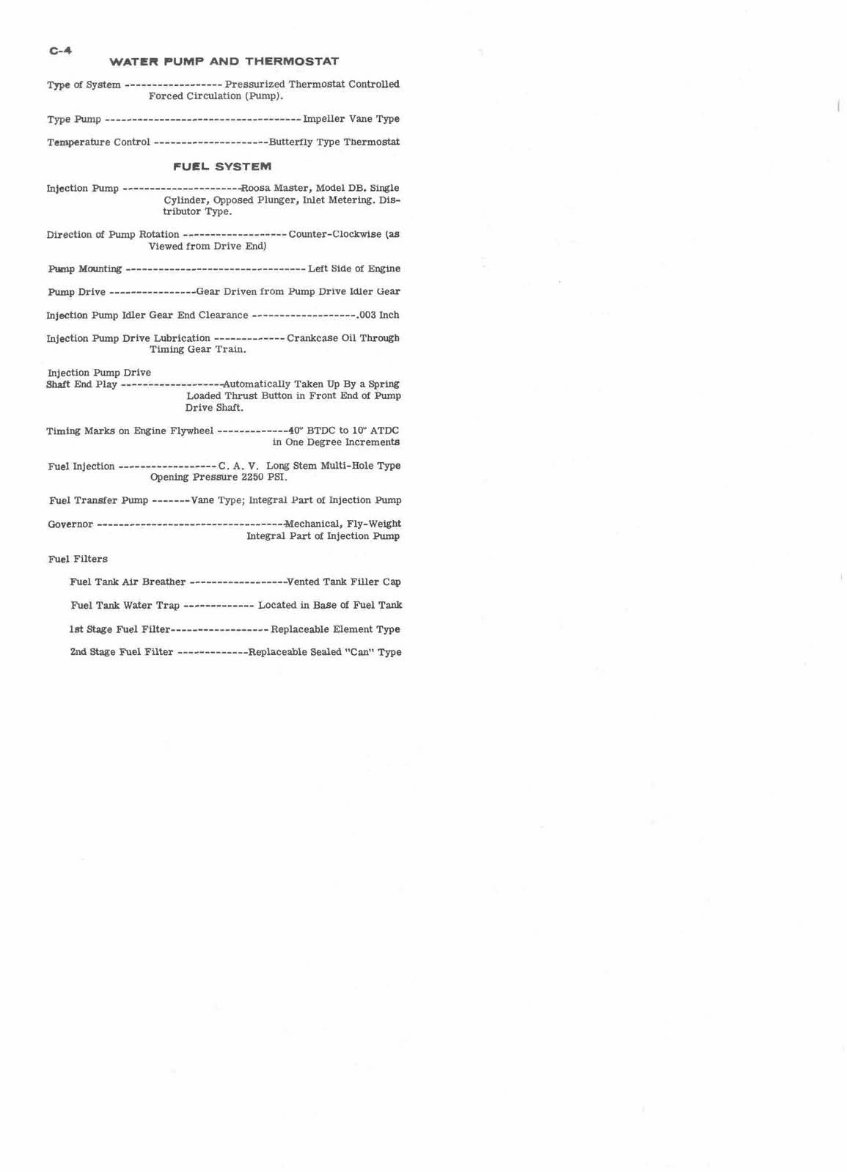
c-4 WATER PUMP AND THERMOSTAT ~yp of System --------------- Pressurized Thermostat Controlled Forced Circulation (Pump). Type Pump -~-ÑÑ---Ñ-------- Impeller Vane Type Temperature Control --------------------Butterfly Type Thermostat FUEL SYSTEM Injection Pump ----------------------Roosa Master, Model DB. Single Cylinder, Opposed Plunger, Inlet Metering. Dis- tributor Type. Direction of Pump Rotation -------------------Counter-ClocKwtse (as Viewed from Drive End) Pump MolJnting --------------------------------- Left Side of Engine Pump Drive ----------------Gear Driven from Pump Drive Idler Gear Injection Pump Idler Gear End Clearance ------------------- .003 Inch Injection Pump Drive Lubrication -------------Crankcase Oil Through Tuning Gear Tram. Injection Pump Drive Shaft End Play ------------------4utomatiCally Taken Up By a Spring Loaded Thrust Button m Front End of Pump Drive Shaft. Timing Marks on Engine Flywheel -------------40" BTDC to 10" ATDC in One Degree Increments Fuel Injection ------------------C. A. V. Long Stem Multi-Hole Type Opening Pressure 2250 PSI. Fuel Transfer Pump -------Vane Type; Integral Part of Injection Pump Fuel Filters 1st Stage Fuel FUter------------------ Replaceable Element Type 2nd Stage Fuel Filter -------------Replaceable Sealed "Can" Type
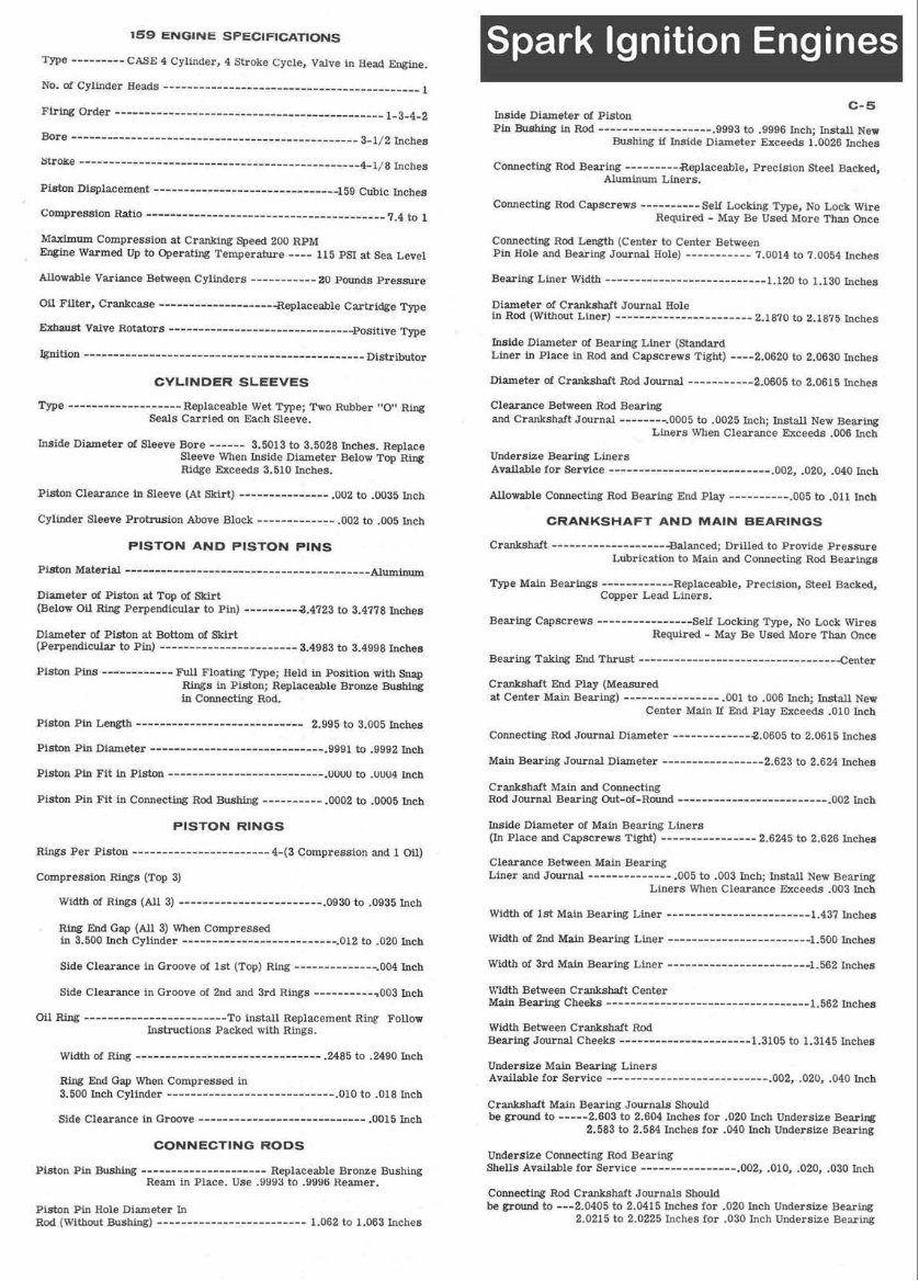
159 ENGINE SPECIFICATIONS Piston Displacement -----------------------a -159 Cubic Inches Compression Ratio ------------- -.--- 7.4 to 1 Maximum Compression at Cranking Speed 200 RPM Engine Warmed Up to Operating Temperature ---- 115 PSI at Sea Level Allowable Variance Between Cylinders ----------- 20 Pounds Pressure Oil Filter, Crankcase ..-- ---- ------- ----- -Replateable Cartridge Type Exhaust Valve Rotators .......................... -----Positive Type Ignition Distributor CYLINDER SLEEVES Type -----------------Replaceable Wet Type; Two Rubber "0" Ring Seals Carried on Each Sleeve. Inside Diameter of Sleeve Bore ------ 3.5013 to 3.5028 Inches. Replace Sleeve When Inside Diameter Below Top Ring Ridge Exceeds 3.510 Inches. Piston Clearance in Sleeve (At Skirt) --------------- .002 to .0035 Inch Cylinder Sleeve Protrusion Above Block ------------- .002 to .005 Inch PISTON AND PISTON PINS Piston Material ---------------------- Aluminum Diameter of Piston at Top of Skirt (Below Oil Ring Perpendicular to Pin) --------- 4.4723 to 3.4778 Inches Diameter of Piston at Bottom of Skirt (Perpendicular to pin) -------------- --------- 3.4983 to 3.4998 Inches Piston Pins --ÑÑ-----Fu Floating Type; Held in Position with Snap Rings in Piston; Replaceable Bronze Bushing in Connecting Rod. Piston Pin Fit in Piston --------------------------.UUW to .UUU4 inch Piston Pin Fit in Connecting Rod Bushing --------L- .0002 to .0005 Inch PISTON RINGS Rings Per Piston -----------------------4-(3 Compression and 1 oil) Compression Rings (Top 3) Width of Rings (All 3) -------- ----- - ---------- -0930 to .0935 Inch Ring End Gap (All 3) When Compressed in 3.500 Inch Cylinder ---- - ..................... .012 to .020 Inch Side Clearance in Groove of 1st (Top) Ring -------------- .004 Inch Side Clearance in Groove of 2nd and 3rd Rings ----------7 003 Inch c-5 Inside Diameter of Piston Pin Bushing m Rod ----------- ---- - --- 9993 to .9996 Inch; Install New Bushing if Inside Diameter Exceeds 1.0026 Inches Connecting Rod Bearing --------- ¥Replaceable Precision Steel Backed, Aluminum Liners. Connecting Rod Capscrews ----------Self Locking Type, No Lock Wire Required - May Be Used More Than Once Connecting Rod Length (Center to Center Between Pin Hole and Bearing Journal Hole) ----------- 7.0014 to 7.0054 Inches Bearing Liner Width -------- ------------------- 1.120 to 1.130 Inches Diameter of Crankshaft Journal Hole in Rod (Without Liner) ---------------A ------- 2.1870 to 2.1875 Inches Inside Diameter of Bearing Liner (Standard Liner in Place in Rod and Capscrews Tight) ~~2.06 to 2.0630 Inches Diameter of Crankshaft Rod Journal -----------2.0605 to 2.0615 Inches Clearance Between Rod Bearing and Crankshaft Journal ---------0005 to .0025 Inch; Install New Bearing Liners When Clearance Exceeds .006 Inch Undersize Bearing Liners Available for Service ---------------------- ----- .002, -020, .040 Inch Allowable Connecting Rod Bearing End Play ---------- .005 to .011 Inch CRANKSHAFT AND MAIN BEARINGS Crankshaft --------------------Balanced; Drilled to Provide Pressure Lubrication to Main and Connecting Rod Bearings Type Main Bearings ------------ Replaceable, Precision, Steel Backed, Copper Lead Liners. Bearing Capscrews ---------------- Self Locking Type, NO Lock Wires Required - May Be Used More Than Once Bearing Taking End Thrust ------------- ----- --------------- -Center Crankshaft End Play (Measured at Center Mam Bearing) ---------------- .001 to .006 Inch; Install New Center Main If End Play Exceeds .010 Inch Connecting Rod Journal Diameter ------------- a.0605 to 2.0615 Inches Crankshaft Main and Connecting Rod Journal Bearing Out-of-Round ----Ñ~--Ñ--ÑÑ--Ñ Inch Inside Diameter of Main Bearing Liners (In Place and Capscrews Tight) -------------- 2.6245 to 2.626 Inches Clearance Between Main Bearing Liner and Journal - ------------- .005 to .003 Inch; Install New Bearing Liners When Clearance Exceeds .003 Inch Width of 1st Main Bearing Liner --- ---- - ---------------- 1.437 Inches Width of 2nd Main Bearing Liner -----------------------1.500 Inches Width of 3rd Main Bearing Liner ------------- ----------- 1.562 Inches Width Between Crankshaft Center Mu Bearing Cheeks----------------------------------1.5 Inches Undersize Main Bearing Liners Available for Service ------------- ------------ -- .002, .020, .040 Inch Crankshaft Main Bearing Journals Should be ground to -----2.603 to 2.604 Inches for .020 Inch Undersize Bearing 2.583 to 2.584 Inches for .040 Inch Undersue Bearing Undersize Connecting Rod Bearing Shells Available for Service ---------------- .002, .010, .020, .030 Inch Connecting Rod Crankshaft Journals Should be ground to ---2.0405 to 2.0415 Inches for .020 Inch Undersize Bearing 2.0215 to 2.0225 Inches for .030 Inch Undersue Bearing
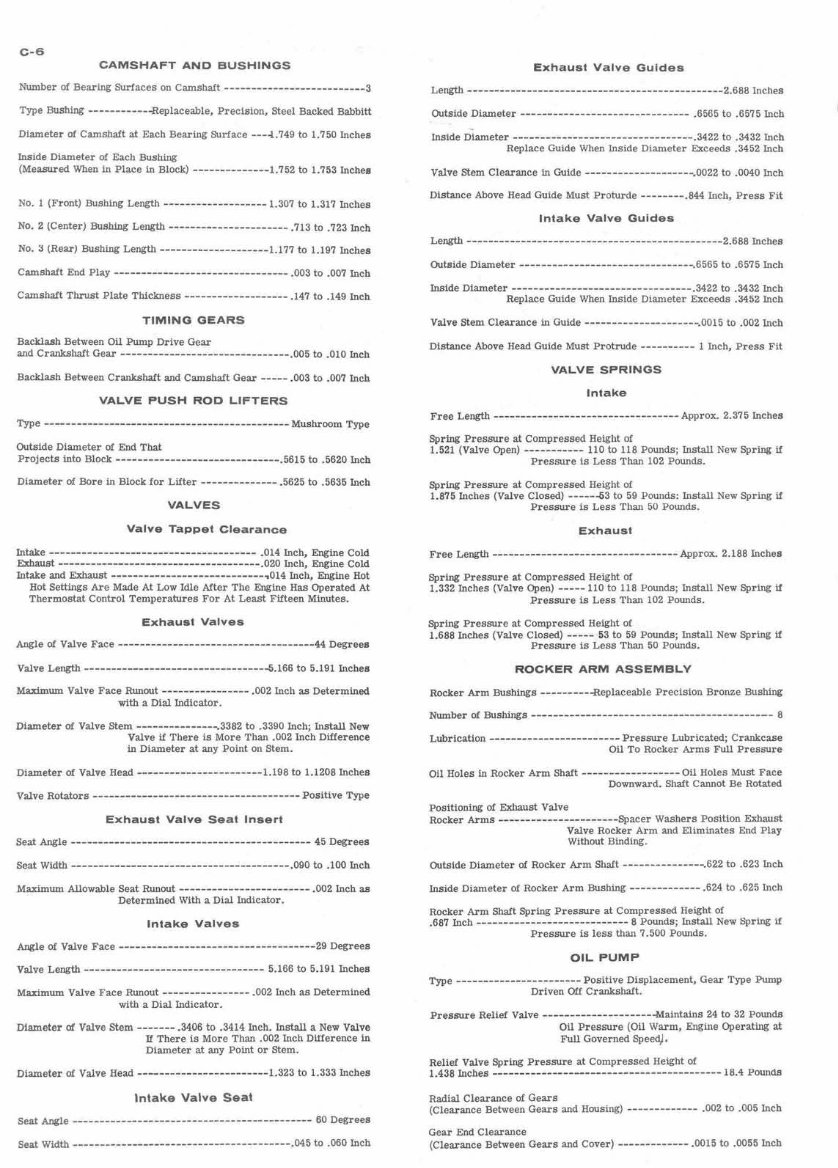
C-6 CAMSHAFT AND BUSHINGS Number of Bearing Surfaces on Camshaft .......................... 3 Type Bushing ---- ------- -Replaceable, Precision, Steel Backed Babbitt Diameter of Camshaft at Each Bearing Surface ---4.749 to 1.750 Inches Inside Diameter of Each Bushing (Measured When in Place in Block) -------------- 1.752 to 1.753 Inches No. 1 (Front) Bushing Length ------------------- 1.307 to 1.317 Inches No. 2 (Center) BUS& Length ------------ ------ ---- .713 to .723 Inch No. 3 (Rear) Bushmg Length .................... 1.177 to 1.197 Inches Camshaft Thrust Plate Thickness ------------------- "147 to ,149 Inch TIMING GEARS Backlash Between Oil Pump Drive Gear and Crankshaft Gear --------------- ---------------- .005 to .010 Inch Backlash Between Crankshaft and Camshaft Gear ----- .003 to .007 Inch VALVE PUSH ROD LIFTERS Outside Diameter of End That Projects into Block -----..----- ------ ----- ----- .5615 to .5620 Inch Diameter of Bore in Block for Lifter -------------- .5625 to .5635 Inch VALVES Valve Tappet Clearance Intake -------------------------------------- .014 Inch, Engine Cold -st --------------------------------+---- .020 Inch, Engine Cold Intake and Exhaust ----------------------------,0 Inch, Engine Hot Hot Settmgs Are Made At Low Idle After The Engine Has Operated At Thermostat Control Temperatures For At Least Fifteen Minutes. Exhaust Valves Angle of Valve Face Ñ--ÑÑ--------ÑÑÑà Degrees Valve Length -------------------------------Ñ5.16 to 5.191 Inches Maximum Valve Face Runout ---------------- .002 Inch as Determined with a Dial Indicator. Diameter of Valve Stem ---------------.3382 to .3390 Inch; Install New Valve if There is More Than .002 Inch Difference in Diameter at any Point on Stem. Diameter of Valve Head ....................... 1.198 to 1.1208 Inches Exhaust Valve Seat Insert Seat Width---------------------------------------- .090 to '100 Inch Maximum Allowable Seat Runout ........................ .002 Inch as Determined With a Dial Indicator. Intake Valves Angle of Valve Face Ñ---ÑÑÑÑ---ÑÑÑ- Degrees Maximum Valve Face Runout ---------------- -002 Inch as Determined with a Dial Indicator. Diameter of Valve Stem ------- .3406 to .3414 Inch. Install a New Valve If There is More Than .002 Inch Dilference in Diameter at any Pomt Or Stem. Diameter of Valve Head - ------ ----------------- 1.323 to 1.333 Inches Intake Valve Seat Seat Angle -------------------------------------------- 60 Degrees Outside Diameter ------ ......................... .6565 to .6575 Inch Inside Diameter ................................. .3422 to .3432 Inch Replace Guide When Inside Diameter Exceeds 3452 Inch Valve Stem Clearance In Guide --------------------.002 to -0040 Inch Distance Above Head Guide Must Proturde --------.a44 Inch, Press Fit Intake Valve Guides Valve Stem Clearance in Guide ..................... .0015 to .002 Inch Distance Above Head Guide Must Protrude ---------- 1 Inch, Press Fit VALVE SPRINGS Intake F~~ Length---------------------------------- Approx. 2.375 Inches Spring Pressure at Compressed Height of 1.521 (Valve Open) ----------- 110 to 118 Pounds; Install New Spring il Pressure is Less Than 102 Pounds. Spring Pressure at Compressed Height of 1.875 Inches (Valve Closed) ------63 to 59 Pounds: Install New Spring if Pressure is Less Than 50 Pounds. Exhaust Spring Pressure at Compressed Height of 1.332 Inches (Valve Open) ----- 110 to 118 Pounds; Install New Spring if Pressure is Less Than 102 Pounds. Spring Pressure at Compressed Height of 1.688 Inches (Valve Closed) ----- 53 to 59 Pounds; Install New Spring if Pressure is Less Than 50 Pounds. ROCKER ARM ASSEMBLY Rocker Arm Bushings ----------Replaceable Precision Bronze Bushing ~~b~i ------ + ------ Pressure Lubricated; Crankcase Oil To Rocker Arms Full Pressure Oil Holes in Rocker Arm Shaft ------------------ Oil Holes Must Face Downward. Shaft Cannot Be Rotated Positioning of Exhaust Valve Rocker Arms ----------------------Spacer Washers Position Exhaust Valve Rocker Arm and Eliminates End Play Without Binding. Outside Diameter of Rocker Arm Shaft ------------ 622 to 623 Inch Inside Diameter of Rocker Arm Bushing ---------- .624 to .625 Inch Rocker Arm Shaft Spring Pressure at Compressed Height of .687 Inch 8 Pounds; Install New Spring if Pressure is less than 7.500 Pounds. OIL PUMP Type -----------------------Positive Displacement, Gear Type Pump Driven Off Crankshaft. Pressure Relief Valve ---------------------Maintains 24 to 32 Pounds Oil Pressure (Oil Warm, Engine Operating at Full Governed SpeedJ* Relief Valve Spring Pressure at Compressed Height of 1.438 Inches .......................................... 16.4 Pounds Radial Clearance of Gears (Clearance Between Gears and Housing) ------------- .002 to .005 Inch Gear End Clearance (Clearance Between Gears and Cover) ------------- -0015 to -0055 Inch
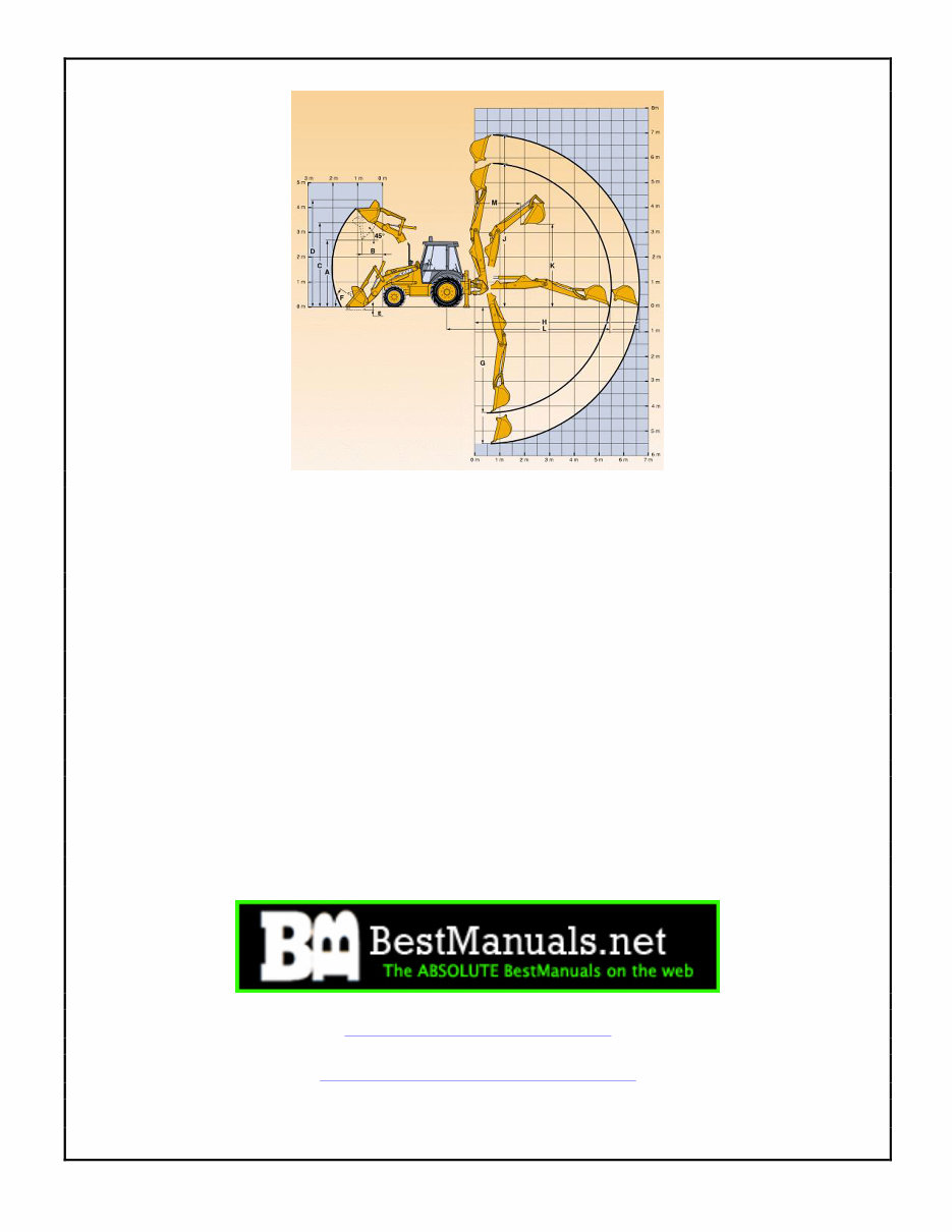
This factory manual for the Case 580 Construction King 1966-1971 is an essential resource for maintaining and servicing your equipment. It contains over 850 pages of detailed diagrams and manufacturer specifications, making it invaluable for both professional mechanics and DIY enthusiasts.
The manual covers the following Serial Numbers and Years for the 580CK Tractor 1966-1971:
Beginning S/N - End S/N - Year
8279001 - 8307000 - 1966
8307001 - 8332500 - 1967
8332501 - 8356500 - 1968
8356507 - 8650000 - 1969
8650001 - 8674000 - 1970
8674001 - 8697900 - 1971
This improved manual includes bookmarks, searchable text, index, and improved quality. It is available in English and compatible with both Windows and Mac systems. The manual is in PDF format and consists of 853 pages.
The contents of the manual are organized into the following sections:
GENERAL
ENGINES
FUEL SYSTEM
HYDRAULICS
STEERING
POWER TRAIN
BRAKES
ELECTRICAL
MOUNTED EQUIPMENT
TROUBLESHOOTING
Additionally, the manual contains complete schematics and color illustrations, making it easy to follow for users of all levels. It is completely searchable and bookmarked for easy navigation. The PDF format allows for zooming, printing, and saving, ensuring convenience and durability.
For immediate access to this invaluable resource, click the button now. Please note that the document may require the latest version of Acrobat Reader for optimal display.
For any inquiries about other manuals, feel free to reach out via email.
Recently Viewed
5,521,897Happy Clients
2,594,462eManuals
1,120,453Trusted Sellers
15Years in Business
Price:
Actual Price:
1966-1971 Case 580CK Construction King 580 CK TLB Tractor Service & Repair Manual