


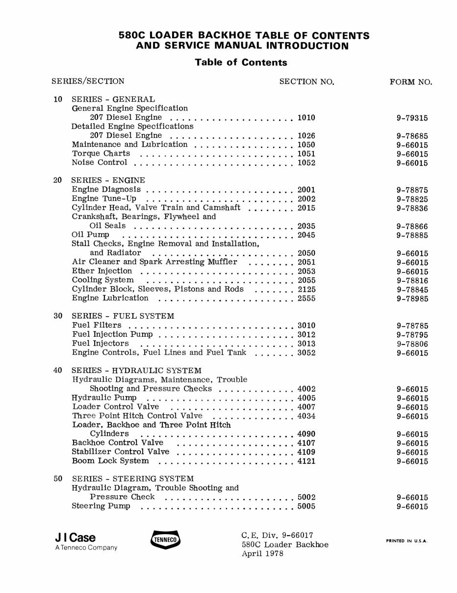
580C LOADER BACKHOE TABLE OF CONTENTS
AND SERVICE MANUAL INTRODUCTION
Table of Contents
SERIES/SE CTION
10 SERIES - GENERAL
General Engine Specification
SECTION NO.
207 Diesel Engine ...... • ........... •.• 1010
Detailed Engine Specifications
207 Diesel Engine ............. • ....... 1026
Maintenance and Lubrication ................. 1050
Torque Charts .......................... 1051
Noise Control ................... • ...... . 1052
20 SERIES - ENGINE
Engine Diagnosis . . . . . . • . . . . . . . . . . . • . • • • . . 2001
Engine Tune-Up ......................... 2002
Cylinder Head, Valve Train and. Camshaft .•.•..•. 2015
Crankshaft, Bearings, Flywheel and
Oil Seals ........ • ....... • .... •..•.. 2035
Oil PuInp ....... •••.•.•...•...•• ...... 2045
Stall Checks, Engine Removal and Installation,
and Radiator ...... • ......... •• ...... 2050
Air Cleaner and Spark Arresting Muffler ...••••. 2051
Ether Injection ....... • ...... • ..... •.. . .. 2053
Cooling System ............. •• ..... •••.. 2055
Cylinder. Block, Sleeves, Pistons and Rods ....... 2125
Engine Lubrication ..• ..... •.•• ........ •.. 2555
30 SERIES - FUEL SYSTEM
Fuel Filters ............... •...• ..... ••• 3010
Fuel Injection PuInp ..................... •. 3012
Fuel Injectors .......................... 3013
Engine Controls, Fuel Lines and Fuel Tank ....... 3052
40 SERIES - HYDRAULIC SYSTEM
Hydraulic Diagrams , Maintenance, Trouble
Shooting and Pressure Checks ............. 4002
Hydraulic PUInp ...... • .................. 4005
Loader Control Valve ..................... 4007
Three Point Hitch Control Valve ............. . 4034
Loader, Backhoe and Three Point Hitch
Cylinders ............ •• ...... ••..•• 4090
Backhoe Control Valve ............ •.•.•.•. 4107
Stabilizer Control Valve .... •..• ...... •••... 4109
Boom Lock System ..... •..•.•.•...• ...... 4121
50 SERIES - STEERING SYSTEM
Hydraulic Diagram, Trouble Shooting and
Pressure Check ................. • .... 5002
Steering Pump ................... •.•.•.• 5005
J I Case
A Tenneco Company
C. E. Div. 9-66017
580C Loader Backhoe
April 1978
FORM NO.
9-79315
9-78685
9-66015
9-66015
9-66015
9-78875
9-78825
9-78836
9-78866
9-78885
9-66015
9-66015
9-66015
9-78816
9-78845
9-78985
9-78785
9-78795
9-78806
9-66015
9-66015
9-66015
9-66015
9-66015
9-66015
9-66015
9-66015
9-66015
9-66015
9-66015
PRINTED IN U.S.A .
2
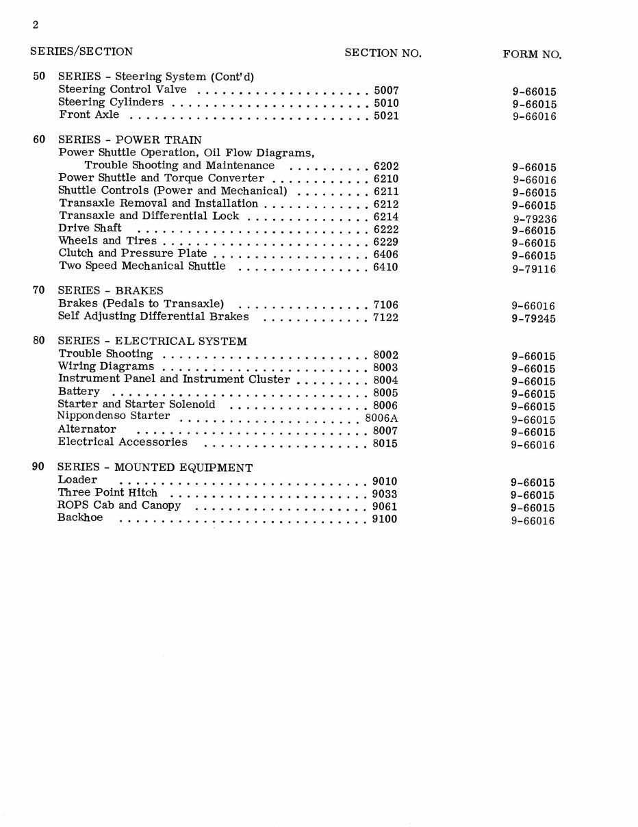
SERIES/SECTION SECTION NO.
50 SERIES - Steering System (ContI d)
Steering Control Valve ..... ••..•••.•.•••••. 5007
Steering Cylinders ........ •••••..•..•.•••• 5010
Front Axle ..•.• ..... •••••..••••• ....... 5021
60 SERIES - POWER TRAIN
Power Shuttle Operation, Oil Flow Diagrams,
Trouble Shooting and Maintenance ...•• ..... 6202
Power Shuttle and Torque Converter .•...•.••..• 6210
Shuttle Controls (Power and Mechanical) •••• ..... 6211
Transaxle Removal and Installation .......... •.• 6212
Transaxle and Differential Lock ...• ........ ••. 6214
Drive Shaft ..• ............. • ......... •. 6222
'Wheels and Tires ..•• ............ •• ....... 6229
Clutch and Pressure Plate ............ ••• .... 6406
Two Speed Mechanical Shuttle .... •...•.•.•... 6410
70 SERIES - BRAKES
Brakes (Pedals to Transaxle) .. ....... •.•..•. 7106
Self Adjusting Differential Brakes ...•...• .... • 7122
80 SERIES - ELECTRICAL SYSTEM
Trouble Shooting .......... • ............ •. 8002
Wiring Diagrams • .... • ....... •.• ..... •.• 8003
Instrument Panel and Instrument Cluster •••..•... 8004
Battery ........ • .... •••..•.•.•...•••.. 8005
Starter and Starter Solenoid .• ....... ••• .... • 8006
Nippondenso Starter ...................... 8006A
Alternator • . • • . . . . . . . • . . . . . . . . . . . . . . . . 8007
Electrical Accessories ....... •.•..• ....... 8015
90 SERIES - MOUNTED EQUIPMENT
Loader •.•..• .............. •.•.•••..• 9010
Three Point Hitch ..•.•••••••••..•••..•.•. 9033
ROPS Cab and Canopy ..•.•.••..•...•.•••.. 9061
Backhoe ..... •...•..• .... ••• .......... 9100
FORM NO.
9-66015
9-66015
9-66016
9-66015
9-66016
9-66015
9-66015
9-79236
9-66015
9-66015
9-66015
9-79116
9-66016
9-79245
9-66015
9-66015
9-66015
9-66015
9-66015
9-66015
9-66015
9-66016
9-66015
9-66015
9-66015
9-66016
3
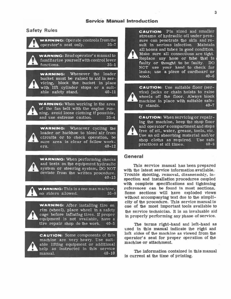
Service Manual Introduction
Safety Rules
/). WARNING: Operatt:! controls from the
.. ope r ato r's seat only. 35-;
/). WARNING: Read operator' s manual to
.. faromarize yourseJfwith controllevcr
functions. 35-1
WARNING : Whenever the loader
bucket must be rai sed to a1d in ser-
r... vicing. block the bucket In place
.. with 11ft cyl1nder stops or a suit-
able safety stand. 40-11
WARNING : When working in the area
/). of the fan belt with the engine run-
.. ning. avoid loose clothing If pOSSIble .
and use extreme C3'.1tion. 35-4
WARNING: Whenever cyCl1ng Ute
A
l oade r or backhoe to bleec air from
circuits or to check operation, be
sure area Is clcnr of fellow work-
ers. 40 -12
WARNING: When performtng
A and tests on the equtpm2nt hydraultc
.. system or steering systel1"., DO l'\OT
devIa te from the wr itten procedure.
40-13
WARNING : ThiS is a one man machine,
.. no riders allowed. 3!J - t'
WARNING: After Installlng tire on
A
riro (wheel), place wh ee l In a saft:ty
cage before inflaUng tires. If proper
equIpment Is not available, ha\'e a
tir e repair shop do the work. 40-5
CAUTION: Some components of this
machine are very heavy. ese sult-
h ab le lifting equipment or additional
.. help as Instructed in this service
manuaL 40-10
General
'Ibis service manual has been prepared
with the latest service information avaUable.
Trouble Shooting, removal, disass e mbl y. in -
spection and installation procedures coupled
with complete specific ations a!ld tightening
referonces oan be found In most sections .
Some sections will have exploded views
without accompanying text due to the simpl1-
city of the procedure. This service manual1s
one of the most Important tools available to
the servi ce technician. It is an invaluable aid
in properly performing any phase of service.
The terms right-band and le ft - hand as
used In this manual indicate the right and
left sides of the mach ine as viewed from the
operator' 6 seat for proper operation of the
machine or attachment .
The information contained in this manual
is current at the time of printing.
http://stores.ebay.com/UsefulCDs
4
Table of Contents
The preceedlng pages contain a Table of
Contents wblcb 118t the Series number and
title, and the sections contained in each series.
The individual sections, where required. will
have a Table of Contents on the second page
of that section.
Page Numbers
All page numbers consist of two sets of
digits separated by a daSh, such as 4002-9.
The digits preceeding the daSh identify the
section. The digits following the dasb repre-
sent the conaecutive page mllnber within that
section. Page numbers will be found at the
upper right or left of each page.
Text
If this manual covers more than one
machine, or different models of component
parts (planetary axles, gear boxes, control
valves, etc.) the procedures will apply to all
unless otherwise noted.
Illustrations
Where possible, Ulustrations are placed
as close as possible to the accompanying
text and should be used as part of the text.
Serial and Model Numbers
When requisitioning repair or replace-
ment parts as it may be necessary tofurn1Sh
the parts department with one or both num-
bers Serial and model numbers will be
found in the following locations.
Machine - Plate fastened to left front
cab or canopy mounting bracket. Also
stamped on top of chassis behind left-
hand hydraulic reservoir.
Engine - Right-hand side of block below
starter.
COIT4>onent parts - plate attached to part
or number stamped in part.
Torque References
Essentially two grades of fasteners
(bolts, nuts and screws) are used on Case
machinery. They grade 5 and grade 8.
Refer to Section 1051 for torque spe cific a-
tions and means of Identification.
The specifications in Section 1051 are
standard torque values and Should be used
on all fasteners during assembly and in-
stallation unless special torque values are
noted in a particular section.
Classification of Lubricants
Oils, lubricants, and grease are classi-
fied and graded accordlngto standards recom-
mended by the Society of Automotive Engi-
neers (SAE). the American Petroleum Insti-
tute (APl), and the National Lubricating
Grease Institute (NLGI).
Engine Oil
The SAE number indicates the viscosity
of engine oils, for example, SAE ao, a single
grade oU. Engine oils are also identified by
dual numbers, SAE lOWaO, a multigrade 011.
The API clauification (MS DS SD CAl
defines 011 performance in terms of engine
usage. Only olls specified in Section 1050
should be used. These oils contain sufficient
chemical additives to provide maximum en-
gine protection. Both the SAE grade and API
designation must be found on the container.
Gear Lubricant
The SAE grade mlmber also indicates the
viscosity of gear lubricantsdeflnedbyMIL-L
-2105B. An example is SAE 90, a medlumvi8-
cosity lubricant.
Grease
Semi - soUd lubricants specified for pivot
points must be that specified in Section 1050.
You're Reading a Preview
What's Included?
 Lifetime Access
Fast Download Speeds
Offline Viewing
Access Contents & Bookmarks
Full Search Facility
Print one or all pages of your manual
$52.99
Case 580C TLB Tractor Service Manual, Owners & Parts Catalog -3- Manuals -
Viewed 35 Times Today

What's Included?
Lifetime Access
Fast Download Speeds
Offline Viewing
Access Contents & Bookmarks
Full Search Facility
Print one or all pages of your manual
$52.99

Secure transaction
What's Included?
Lifetime Access
Fast Download Speeds
Offline Viewing
Access Contents & Bookmarks
Full Search Facility
Print one or all pages of your manual
Description
- This is the Complete Factory Case 580C Tractor Loader Backhoe Service Manual and the Parts Catalog Manual and the Operators Manual.
- The 580C Tractor was made 1975-1980. These Manuals cover all the years it was made.
- The SERVICE MANUAL includes needed instructions to maintain and service your tractor using detailed diagrams and manufacturers specifications. This Service Manual has Complete Schematics and Color Illustrations.
- The ILLUSTRATED PARTS CATALOG has detailed diagrams and illustrations with exploded views and part numbers for every part on your tractor.
- The OPERATORS MANUAL is the same exact manual you received when the tractor was new. It covers all aspects of using/operating your tractor.
- Navigation is simple with convenient chapter bookmarks and ability to search by keyword.
- Print out entire manual or just what you'll be working on.
- INSTANT - NO WAITING
- LANGUAGE: English
- FORMAT: ped
- COMPATIBLE: Win/ Mac
- PAGES: 801 SM, 591 PC, 185 OM
- SEARCHABLE - BOOKMARKED - INDEXED
- These Manuals are clear and written in a way so that just about anybody can follow them.
- All 3 Manuals are BOOKMARKED - So you can Find What You Need To Know Quickly - Just Click on the Bookmark & that Page Comes Up.
- All 3 Manuals are SEARCHABLE - Just type in what you are looking for & that Page will come up.
- SERVICE MANUAL SECTIONS INCLUDES:
- 10 Series - General
- 20 Series - Engine
- 30 Series - Fuel System
- 40 Series - Hydraulic System
- 50 Series - Steering System
- 60 Series - Power Train
- 70 Series - Brakes
- 80 Series - Electrical System
- 90 Series - Mounted Equipment
- OWNERS MANUAL SECTIONS INCLUDES:
- Introduction
- Safety
- Specifications
- Instruments & Controls
- Operating Instructions
- Operating Tips
- Fuels & Lubricants
- Maintenance / Lubrication
- All are on Easy to read files.
- These Manuals can be viewed on any computer, as well as zoomed and printed.
- Mechanical details and step-by-step instructions you will need are included.
- ONLY OUR CASE MANUALS GIVE YOU THE ABILITY TO SEARCH THE MANUALS - AND FIND WHAT YOU NEED IMMEDIATELY!
- FYI: 580 denotes the Machine Model. The letter after the model number denotes the Series. The letters CK follow all 580 model machines and stand for Construction King. So, 580C CK is a Model 580, Series C, Construction King.
**************************************************************************
TO GET THESE MANUALS IMMEDIATELY -
CLICK THE GREEN & WHITE BUTTON
- at the Top Right-Hand Side of this Page -_
**************************************************************************
We have Thousands of Manuals - email us about any you might need.


