1956-1960 Case 430, 440, 470, 530, 540, 570, 630, 640 Tractor Service & Repair Manual
What's Included?
Lifetime Access
Fast Download Speeds
Online & Offline Access
Access PDF Contents & Bookmarks
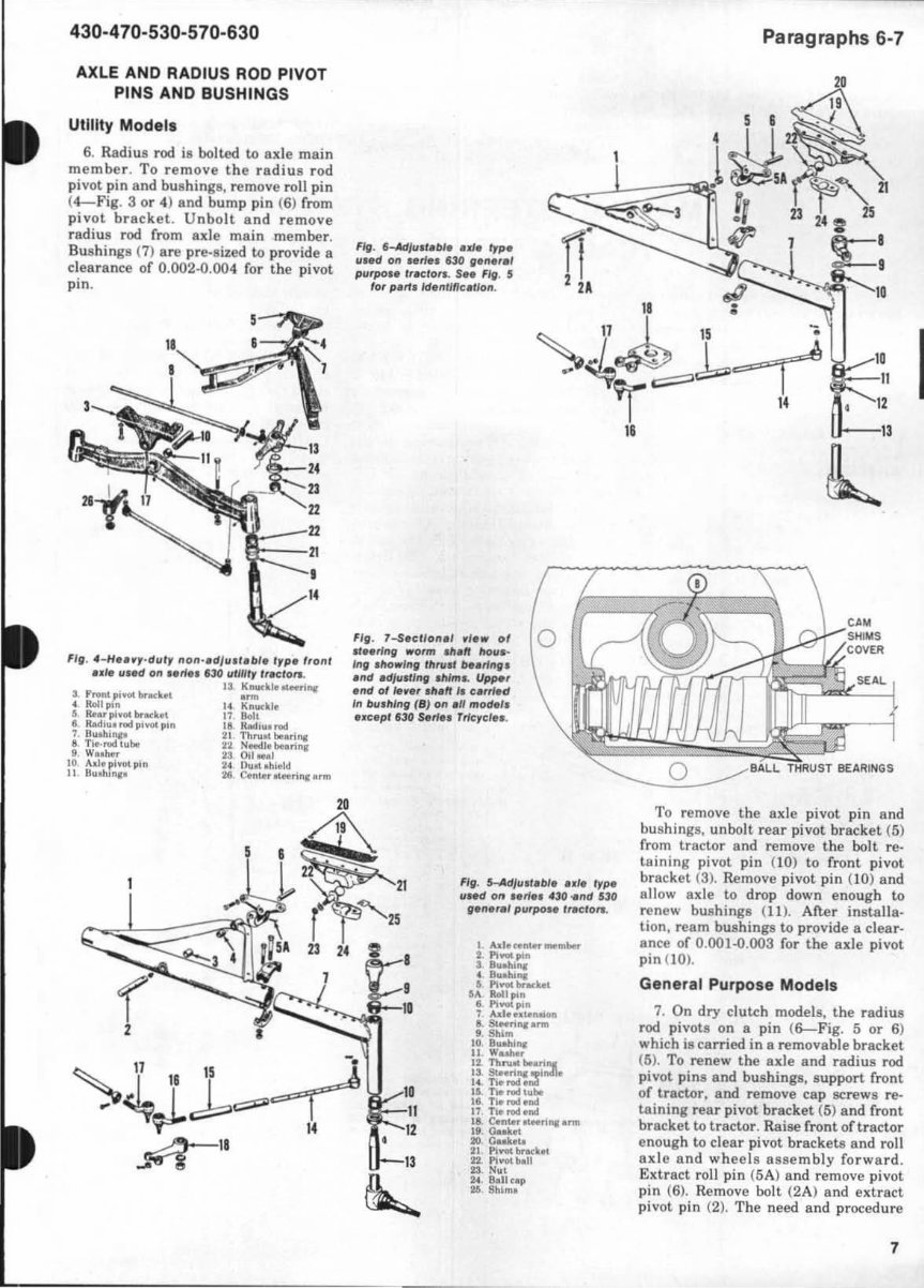
Full Search Facility
Print one or all pages of your manual
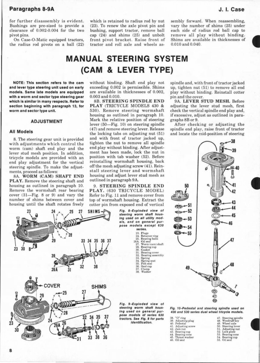
SHOP MANUAL J. I. CASE SERIES 430-440-470-530-540-570-630-640 NOTE: For purpos. s of Identification In th is manual " S.rles 430" Includes Gaso- line and Di esel Model. 430, 431, 440 and 441 : Series " 470" Includes Gasoline and Die sel Model s: " Serln 530" Include. Gasoline, LP-Gas and Dies el Mode" 530, S3OC, 531, S3le . 540, seoc , 541 and S41C: S.,les 570 Includes Gasoline and Olese ' Mode'l: " Serl •• 630" Include. Gasoline and Diesel Models 630, 6l0e , 631 , 63le , 632, 632C, 640, 6COC, 641 and 641C. Tractor •• rial number I, stamped on tractor name plate located on I nstrument pane' of .erles 430 and 440, and on right ,Ide 01 engine hood on 470, 530, 540, 570, 630 and 640 1.,les. Engine •• rlal number I, stamped on right rear corner of engine block. All Series available with Case·O·Malic drive are designated by addition or "C"s uffix to model number. INDEX (By Starting Paragraph) Non-Din el 430-470 S3().S70 630 ----- Die.el ---- 530·5 70 630 MAK ES ................... . CARB URETO R (No t LP'(; •• ) ... "C ASt:-O·MATI C" Clutch .......... . ....... . Control Vah'e .... .. ......... . Con\'er tor PreMure Regu l.tor .. Fluid. Breather & t' iltu ......... . .. ... •.. . Li ukage Adju~tmen ls ........... . ..... •.. . Oper. t io n .................... . .. • ..•... PreMu re Tel l. . . ..... ....... ... ...•.. •. Pump ......... , .... . Torque COI1~erlor Trouble Shooting 2 1 68 ,. 168 168 168 1 68 " ,.. 139 1 39 13? 139 138 138 138 138 137 137 137 137 129 129 129 129 1 34 IH 134 134- 128 128 1 28 128 132 132 132 132 1 38 1 38 138 1 38 '" '" '" '" 130 130 130 1 30
INDEX (By Starting Paragraph)-Con ' !. COOLlNG SYSTEM Radiator .. Thermosta' Wa ter Pum p DI STRIB UTO R DUAL RANGE Con tr ol Cover Overhl ul ...... . Remove & Rein stall DIESEL FUn SYSTEM 81 ... edilli .............. ... .. • ....... . ... fi lterw .. ...... . ...... . Governor .••. •.•.•...•• .... No:r.:r.lu .... ............ ........ . ..... .. Noult: Line rs .. Pump .. DIFFERENTIAL OIFFERE NT I AL LOCK ...... . .. . ELECTR I CAL UN ITS ..... ...... .. ... . ... . . ENGINE CLUTCH Adjus tme nt ............ ....... • ..... . .. Clul ch Shart ... . ........ .. . .. ......... . R&R a nd Overh au l ... ....... . ... .. .. . •. . ENG INE elm FoU owera ...••.. ..••.• .... . •• .•••.• Ca mshaft and Beati np ............... •• .. • tonnecling Rod. & Burinp . ....... . CranlWl .ft & Bearillls ......... . Cylind er Hl';ad ....... . ... ... .. ... . •. •• ..• Cylind~r Sleeyes . . . . . . . . .. . .. •• ... El1II ine Timil1ll .. . ............ ..... . . . Fl ywheel . . . . . ...... ......... • ..• Mli n BearinKa .......... . ..•..•..• Oil Pin ........... .. .. ....... •• ... Oil Pressure ... . ......... ... . ...... .. •... Oi l Pump . ... ..... .......... •. ........ Pistons & Rings ...... ....... ... . ..• ..... Pi Blon Pins .... .... . . ..... . ..... . ..• . .• Pi ston & Rod RemoYal . ... ... .• • .. • .. • .. • Oil Seal, Fron t ... . . ....... • ..... Oi l Se. I. Rur .. . .• ..• ...... Remo ve & Rdr lBta ll ....... .. • ..•.. • .. • .. . Rocker Anna .......... ... •. .. •. . • ...... Timing G.. ,ra ...... . ..... . •..• ...... Timing Gear Coyer .... ...... •..• ..... • .. V, IYe Gu ides & Springe . . . ...• .. • .. • ...... Valve! & Seats . . . . . . •. . .•.. • ... Valye Tappet. . ..... .. .•.. •. .• ... fl NA.L DRIVE Be vel Geua ......... •...•• .... •• .• • ... 8ull Geara ... ........... ... . Bull Pinions .. ..... ... ... .. . FRONT SYSl' EM Axle p;" ot Pin. & 8u.ehil1ll' . ........... •. •. Steering Knuckles ....... . ......... • . ..•.. Tit Rods .... . ...... .......... .. .. . .... . Tricycle ...... ..... .... .. ... .......... . GO VERNOR Adjustment ...... ... ..... .. •. . .• ..• .. . Overh. ul .. .. .... • .... .. . . .. • .. • .. __ ~ __ N~~ ____ _ .ao .. 170 590-510 630 III "' "' II. ISO IS' 15 1 161 170 116 120 123 12 1 '3 .. .. " 45 66 "' 72 .. 71 73 " 66 67 M 54 70 .. " " 54 '9 47 53 1 66 , .2 I .' I •• 6 3 , '09 II. III 11 2 113 II. IS' 15' lSI ,., 17. II . I:!O 123 1 11 53 .. .. .. 45 •• li S 72 .. 71 73 73 66 67 6S " 7. .... " 56 S. " 41 53 166 162 'M 164 6 3 S '09 II. III 112 "' "' 150 152 151 '" 11 6 12. 123 121 53 64 .. " · 16 66 li S 72 I,' 71 7J 73 66 67 65 S. 7. .. " " " ." " 53 166 16' 165 16' 6 'A 5 109 110 430·· 4070 --- --Oie8oC1---- 530·570 630 III "' 11 3 150 IS:.! 151 ., 8'1 108 87 89 103 161 170 11 6 1 211 123 121 53 I,. "" 69 " 66 105 n " " 73 7J " 1,7 1,5 " 70 ." 52 '" 55 " .. 53 166 102 165 164 6 , 5 108 III 112 113 150 152 151 85 . , 108 .7 89 10' '" 170 11 6 120 12' 12 1 53 " .. 69 .. 56 105 72 59 71 71 7J " 67 55 55 70 . ... 52 60 55 " '" 53 16. 162 16 5 '64 • , 5 , "8 III 112 11 3 150 152 15 1 85 .. 108 R7 '" 103 16 1 "' 120 1 23 12 1 53 .. '" 69 " 6b 105 72 " 71 73 n " 67 65 55 70 •• " 60 55 " .. 53 166 163 165 . 64 6 3A 5 108 3
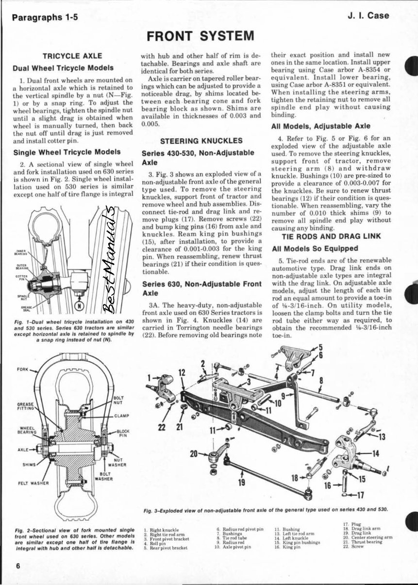
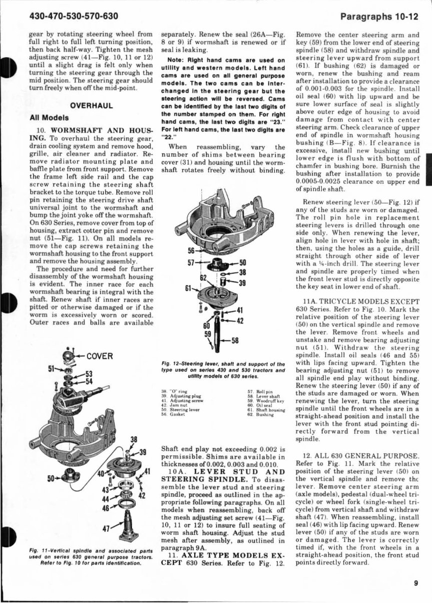
Paragr aphs 1·5 TRICYCLE AXLE Dual Wheel Tricycle Model s 1. Dual front wheels are mounted on a horizontal axle which is reta ined to the vertical spindle by a nut ( N-Fig . 1) or by 8 snap ring. To adj ust the wheel bearings , tighten the spi ndl e nut until a sli ght drag is ob18ined when wheel is manually turned , then back the nut off until dr ag is just removed an d in sta ll cotler pin . Single Wheel Tricycle Models 2. A sectional view of single wheel a nd fork installation used on 630 series is shown in Fig. 2. Single wheel instal- lat ion used on 530 se ri es is s imilar exccplo ne ha lf or lire nAngc is integral Fill. I-Du.' ",11 •• , /ricrel. In, l,lI,tlon on .30 .nd 530 u ri ••. S, rf,. 1130 ,,.clo,. .re .Imll. , ._ c. pl horizon'.' •• ,. I. re/.,n,d /0 'p/ndl • .tI, • ,n,p ringln,t,.d of nul {N}. FlO. 2-SKlkHl.1 .-1.l1li' 01 lor. mounl .d IJngl. Iront l1li'11 •• 1 u •• d on no •• " ... 0111" mod.l. • " .Imll., uc.pl on. II.ff 01 II" II .ng' I. 'n"g'" wltll hub .nd olh" h." I. dlt.c ll .bl •. 6 FRONT SYSTEM with hub and other half of rim is de· tachab le. Beari ng s and axle sh an are identi cal for both series. Axle is carrie r on tapered roller bear- ings which can be adjusted to provide a noticeable drag, by shims located be- tween each bearing cone and fork bearing block as sh own. S hi ms are ava il a bl e in thicknesses of 0. 003 and 0.005. STEERING KNUCKLES Series 430-530, Non-Adjustable Axle 3. Fig. 3 shows a n exploded view of a non-adjustab le front axle of the gene ral t ype use d. To remo ve the stee r ing knuckles, support front of tractor and remove wheel and hub assemblies. Dis· con nect tie-rod and dra g link a nd reo move plugs (I 7). Remove screws (22) and bump king pins (16) from axle and knu ckles . Ream king pin bushings (IS). after installa ti on, to provide a c:Iearance of 0.001·0. 003 for the king pin. When reassembling, renew thrust bearings (2 1) if the ir condition is ques- tionable. Series 630, Non-Ad justable Front Axle 3A. The hea vy-duty. non-adjustable fr ont axle used on 630 Series tr actors is s hown in Fi g. 4. Knu ck les (1 4) are carr ied in Torrington needle bearings (22). Before removing old bearings note J. I. Case their exact poSition and insta ll new ones in the same location. Instal! upper bearing using Case arbor A· 8354 or equivalent . Ins tall low er bearing, using Case ar bo r A-835 1 or equivalent. Wh en installing the steering arms, tighten the retaining nut to remove all spindle end play without ca u sing binding. All Models, Adjustable Axle 4. Refer to Fig. 5 or Fig. 6 for an ex ploded view of the adjustable axle used. To remove the stee ri ng knuckles. su pp ort front of tractor , remove stee rin g arm ( 8) and wit h draw knu ckle. Bushings (10) are pre.sized to provide a clearance of 0.003-0.007 for the knuckles. Be s ure to renew thru st bearings (J2) if their condition is ques- tionable. When reassembling, vary the number of 0.010 thick shims (9) to remove all spindle end play without ca using any bindin g. TIE RODS AND DRAG LINK All Models So Equipped 5. Tie-rod ends are of the renewable automotive type. Drag link ends on non·adjustable axle types are int egral with the drag link. On adjustable axle models. adjust the lengt h of each tie rod an equal amount to provide a toe-in of \oIiI -3/ 16·inch . On utility models. loosen the clamp bo lts and t urn the tie rod tube either way as required. to obtain the recommended \oIiI -31l6-inch toe·in . F/g . 3~.plodld . /,l1li' of non-.dJu." bI. Ironl u" 01 rh. g.n."'tr~ u"d on •• rI •• 430 .nd '30 . 1 Ri.b, knuckl . ~. Ri.ht , Ie I"Od Onn 3. Front piWlt b< .. "", 4 Roll pin ~. ~.rpIWltbra<k'l 6 RlId,P'1"Od plY", pin 7 Buthln• • 6. Tiol"Od tub. 9 R..rluHod 10. A,I. pl _ pin I I lIuohlnr 13 IAn '"" I"Od 0, ... 14 I .. n knuc kl • 1&. Kh .. pin btoohl",. 18. Kllll pi n 11 I'l\lil 18 Orq li nlt • • ", 19 O..,link 20 C.n 'erotHrin.onn 21 Tl"uI' beullll 22 s. .. w • •
430-470-530-570-630 AXLE AND RADIUS ROD PIVOT PINS AND BUSHINGS Utility Models 6. Radius rod is bolted to axle main membe r. To remove the radius rod pi vot pin and bushings, remove roll pin ( 4-Fig. 3 or 4) and bump pin (6) from pivot br acket. Unbolt and remove radiu8 rod from axle main member. Bushings (7) are pre.aized to provide 8 clearance of 0.002-0.004 for the pivot pin . FIll · "-HI •• y·du', non·.d/IIII,bl. Iyp. f,o", ,.Ie lind on •• ri •• flO II11U" 'r,clOI1l. U Khu<U. _ .h", .~ 14 KII""k le L7 Boll 18. Kad'~INHI 21 Th", ... b ... ri ", 22 H .. . II.M. ri ", 23. 0;1_1 24 Du ot.hleld H. Cenlol. Mftri", • .,., F/fl . a-Ad/u, t,bl, .. " type lI .. d on le/W, 530 ,1"1'" purpo .. "Iclo ... s •• FIll. S lor p ert. Idlnlllfe.lloll. FI, . 1-Slcllo",' ., •• 01 .".rinlf wo,m 11"1'" lIou" In, ,110.',." fhrv.' H,rln,. ,nd ,d/usUng . hl,., .. Up~r ,nd 01 Ie.,., .h .ft ,. c.m.d In bu,"'n" (8J on .N mod", .. e.pl 630 S." .. Trlcycl ,., • " II 12 FI~. $-Ad/II."b'• •• Ie 'rpe lI.ed on I'~' 430.nd 530 ~.,..r.1 purpo •• ' "efors. Paragraphs 6-7 " o BALL THRUST BEARINGS To remove the axle pivot pin and bushings. unbolt rear pivot bracket (5) from tr actor and remove the bo lt reo tainin g pivot pin (10) to front pivot bracket (3 ). Remove pivot pin (10) and allow axle to drop down enough to renew bushings (It). After instal\a· lion. ream bushings to provide a clear· ance of O.OO I..() .OO3 for the axle pivot pin (1 0 ). General Purpose Models 7. On dry clutch models, the radius rod pivots on a pin (6-Fig. 5 or 6) which is car ried in a removable bracket (5). To renew the axle and radius rod pivot pins and bushings, s upport front of tractor, and remove cap screws reo taining rear pivot bracket (5) and front bracket to tractor. Raise front oetractor enough to clear pivot brackets and roll ax le and wheels assemb ly forward . Extract roll pin (5A) and remove pivot pin (6). Remove bolt ( 2M and extract pi vot pin (2 ). The need and procedure 7 I
Paragraphs 8·9A for further dis88sembly is evident. Bu shings are pre.sized to provide a clearance of 0.002-0.004 for the two pivot pins . On Case-O-Malic equipped tractors, the radi us rod pivota on a hall (22) which is retained to rad ius rod by nut (23). To renew the axle pivot pin and hushing, support tractor, remove hall cap (24) and sh ims (25) Bnd unbolt front pivot bracket . Raise front of tractor and roll axle and wheels 8S- J. I. Case sembly forward. When reassembling, vary the number of shi ms (25) under each side of radius rod ball cap to remove all play wit hout binding. Shims are available in thicknesses of 0.010 and 0.040 MANUAL STEERING SYSTEM (CAM & LEVER TYPE) NOTE : This •• cllon ref.r. to the cam end lever type .t •• rlng unit lolled on •• r ty model • . Sam. lete models Ire equipped with I worm Ind •• ctor type .t •• rlng g .. r which I •• Imllir In mlny r"p.ct •. R.'.r to .. cllon b'glnnlng with p.,lgrlph 13, for worm Ind .. ctor tYPI unit. ADJUSTMENT All Models 8. The steering gear unit is provided with adjustments which cont rol the worm (c am) shan. end play and the lever stud mesh position. In addit ion, tricycle models are provided with an end play adjustment ror the vertical steer ing spindle. To make the adjust- ments, proceed 8S rollows: SA. WORM (C AM ) SHAFT END PLA V. Remove the steering shaft. and housing as outlined in paragraph 10. Remove the wormshaft. rear bearing cover (31 -F ig. 8 or 9) and vary the number or shims bet.ween cover and housing until t.he shaft rotates rreely 8 without binding. Shaft. end play not exceeding 0.002 is permissible. Shims are availab le in thicknesses or 0.002, 0.003 and 0.010. 88 . STEERING SP I NDLE END PLA V (TRICYCLE MODELS 430 & 530 ). Remove stee ring wormshart housing 88 out.lined in paragraph 10 . Mark the relat.ive position or steering lever ( SO-Fig. 10) on steering spindle (47 ) and remove steering lever. Re lease the locking tabs on adjusting nut (51) and with rront or tractor jacked up, tighten the nut to remove all spindle e nd play without binding. After adjust- ment has been made, lock the nut in position with tab washer (52). Berore reinsta lling wormshaft housing, back ofT the mesh adjus ting screw (4 O. Rein- st.nll stee ring lever and worms hart housing and adjust lever st ud mesh as out lined in paragraph 9A. 9. S TEERING SP INDLE END PLA V. ( 630 TR ICVC LE MODEL) Rerer to Fig. 11 and remove cover rrom t(lp or wormshafl. housing. Extrnct the cotter pin from exposed end of vertical SHIMS SHIMS FIg . • --Erplod.d " .... 01 ,' •• rl"g ... orm ."." "ou.- '''g II.H 0" .11 11111/1)' mod- .1., ."d 0" g.n.,.' pllr · po •• mod., • • xc.p' 830 •• ri ••. 23. Pl uco ~4 RecalM,n", ~: ~i!!::f _II. 21. W_ ( ..... )oIlaft ~. Burl", '''1' 30. G .... .. 31 .,..n .... o .. ' 32. Buri ... _mbl1 33. Spri nl U. Spri ...... t 3/1. Felt .. l ,. Stal_"" 37 Cl .... , 38. w ........ Fl. . ,-t. plod.d fl .... of · .' •• rl"" ... orm .".11 "011 1- In, 1I •• d 0" g.n.r.' pllf · po •• mod~11 01 •• " •• 130 ,,,do ft. S •• Fig. I fM p.rt. Id."rmuflon. spindle and, with rrontortraclor jacked up, tighten nut (51) to remove all e nd play without binding. Reinstall cotter pin and t.he cover. 9A. LEVER STUD MESH. Berore adjusting the lever stud mesh, first check the vertical spindle end play and, ir excessive. adjust as outlined in para- graphs 88 or 9. After checking or adjusting t he spindle end play, raise rront. or tractor and locate the mid-position or stee ring __ 51 ~ 52 8_ 53 0-54 0-55 49 Fig. JO-P.d •• , .1 ."d "tt"", . plndl. III.d 0" 430 .nd 530 I. " .' du.' .... " •• /I"Crc/. mod., •. 3&, " O"ri ... ~ ~=~jC,l ... 41 "'Ii ... , .... ""' 42. J."'ftOlI 43. Buri ...... , 44 Buri"' ...... 43. Th"' .... her 48. 0;( ... 1
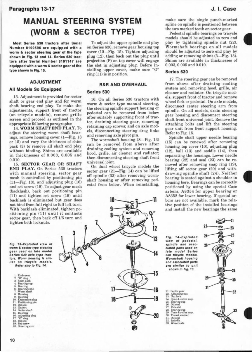
430·470·530·570·630 gear by rotaling steering wheel from full right to full left turning position. then back half-way. Tighten the mesh adjusting screw (41 - Fig. 10, 11 or 12 ) until a slig ht drag is felt only when turning the sleering gear through the mid position. The stee ring gear should turn freely when ofT the mid-point. OVERHAUL All Models 10. WORMSHAFT AND HO Us.. ING. To overhaul the steering gear, drain cooling system and remove hood, grille. air cleaner and radiator. Re- move radiator mounting plate and bame plate from front support. Remove the frame left side rai l and the cap sc r ew ret aining the steering s haft bracket to the to rq ue tube. Remove roll pin retaining the steeri ng drive ahaft universal joint to the worms haft and bump the joint yoke ofT the wormahaft. On 630 Series, remove cover from top of housing, extract cotter pin and remove nut < 51-Fig. II). On all modele reo move the cap screws retaining the wormshaft housing to the front su pport and remove the housing assembly. The procedure and need for further disassembly of the wormshaft housing is ev ident. The inner race for each wormshaft. bearing is integ ral with the shaft.. Renew sh aft if inner races are pitted or otherwise damaged or if the worm is excellBively worn or sco red . Outer ra ces and ball s are available FI, . JI-VI,.'CI' .p lnd l. Ind ... OCIII.d PI'" " .. d on .. ri., 130 ,1""11 P"'PO" 1,l c lo,.. R.f.r 10 FI,. 10 l or pi " , Id."l/flullo" . sepa rately. Renew the sea l (26A-Fig. 8 or 9) if wormshaft. ill renewed or if seal is leaking . Note: Right hind clml Ire u •• d on utility Ind •• • tern mod el •. Lelt hind elm • .,. ulld on In VI".,.I purpo •• mod., •. Thl two elm. can b. Inter· ehlng.d In th •• te.,'ng III" but th. Itl.rlnll Iction will be rlv.r •• d. Cam. cln b. Id.ntlfled by th. lui two digit. 01 th. numb., Itlmped on thlm. FOI right hind cam. , the 1111 two dill"' ar. "23." For I.n hind Clm., the II.t two digit. al' "22 ." When rea8llembling, vary the number of s hime between bearing cover ( 31) and housing until the worm- shaft. rotates freely without binding . FI, . 12-$rllrl", Ie .. " .nlll ."d .IIpPOrl of l he l~pI II It'd 0" .. ri •• 430 end 530 traclor. I"d 111/1/1, modfll. of 130 •• rI ••. 38 "0" ,;'" :III "<11_,,,,,,, ... 41 ,,<\i ....,.., ...... H. J.mnul 100 S-"'" 1 ._ " C . .... l 61 Moll,," " [ ..... 011.1'1 !WI Wood",lTk., 110 Oil ... l II !!h.1'! """".J .2 BuNoI .. Shaft end play not exceeding 0.002 is permi ss ible . Shims ar-e available in thickne8llesofO.002, 0.003 and 0.010. l OA. LEVER STUD AND STEE RIN G SPINDLE , To di ... - semble the lever stud and steer ing spindle, proceed as outlined in the ap- propriate following paragraphs . On all models when reaasembling , back oJT the mesh alljusting set screw (4 I- Fig. 10, 11 or 12 ) to insure full seat ing of worm s haft housing. Adj ust the st ud mesh after a8llembly, as outl ined in pa ra grap h 9A. 11. AXLE TYPE MODEL S EX- CEPT 630 Seriee. Refer to Fig. 12. Pa ragraphs 10·12 Remove the center steering arm and key (59) from the lower end of steeri ng spindle (58) and withdraw spindle and stee ring lever upward from support (61). If bushing (62) is damaged or worn, renew the bushing and ream after installation to provide a clearance of 0.001-0.003 for the spindle. InSlall oil seal ( 60 ) with lip upward and be sure lower lIunace of seal is IIlightly above oute r edge of housing to avo id damage from contact with center steering arm . Chock clearance of upper end of spindle in wormshaft housing bushing (B- Fig . 8 ). If clearance is excessive, install new bushing until lower edge is flush with bottom of I chamfer in bushing bore. Burnish the bushing after in stallat ion to provide 0.0005-0.0025 clearance 011 upper end of spindle s haft . Renew steering lever (5()........ Fig. 12) if any of the studs are worll or damaged. The roll pin hole in replacement steering levenl is drilled through one side only. When renewing the lever, align hole in lever with hole in shaft: then , using the holes as a guide, drill st r aight through other side of lever with a '4-inch drill. The steering lever and spindle are properly timed when th e front lever stud is directly opposite the key seat in lower end of shaft. 11A. TRICYCLE MODELS EXCEPT 630 Series . Refer to Fig. 10. Mark the relative position of the steering lever (50) on the vertical spindle and remove the lever. Remove front wheels and unstake and remove be8ring adjusting nu~ {51l. Withdraw the steering spindle. Install oil seals (46 and 55) with lips facing upward. Tighten the bearing adjusting nut (5 1) to remove all spindle e nd play without binding. Ren ew the stee ring lever (50) if any of the st uds are d amaged or worn. When renewing the lever, turn the steering spindle until the front wheels are in a IItraight-ahead position and install the lever with the front stud pointing di- rectly forward from the vertical spindle. 12. ALL 630 GENERAL PURPOSE . Refer to Fig. 11. Mark the relative position of the stee r ing lever (50) on the vertical spindle and remove the lev er. Remove center stee r ing arm (axle models), pedestal (dual-wheel tri- cycle) or wheel fork (single-wheel tri- cycle) from vertical shaft and withdr8w shaft (47 ). When reall8embling, install seal (46) with lip facing upward. Renew lever (50) if any of the studs are worn or damaged . The lever is correctly limed if, with the front wheels in a straight-ahead position, the front stud points directly forward. 9
Paragraphs 13-17 MANUAL STEERING SYSTEM (WORM & SECTOR TYPE) MOlt Se,' .. 530 tractor. atter S.rll' Numb., 818115118 .r. equi pp ed with. worm a •• clor .t •• rlng gu, 01 the type ahown In Fig . 13 and 14, Serl •• 63 0 trlc, to r. atter S.rlel Numbe, 81 91147 . r. equipped with. worm' •• ctor gn, 01 the type ahown In Fig. 15. ADJUSTMENT All Model, So Equipped 13. Adjulltment ia provided for sector shaft or gear end play and for worm shaft bea ring end play. To make the adjustments, support front of tractor (o n tricycle models ), remove grille scr een Bnd proceed 8S outlined in t he a ppropriate following paragraphs: 14. WORM SHAFT END PLAY. To adjust the IItee ring worm shaft bear· ings, remove housing cover (I- Fig. 13 or 15) and vary the thic:kneu of shim pack (3) to remove all shaft end play wit hout binding. Shims are available in thickn esses of 0.003, 0.005 and 0.010. 15. SECTOR GEAR OR SHAFT END PLAY. On Series 530 tractors with manual s teering , secto r gea r mesh is conlrolled by positioning pin (I I-Fig . 13), and adjusting plug (16) and set screw (19). To adjust gear mesh (backlash), back out positioning pin (11) and tighten set screw (19) until backlash is eliminated but gear does not bind from full r ight to full left turn . With backlash eliminated, tighten po- s iti oning pin (11) unti l it contacts sector gear, then back 01T 116 turn and tighten both locknuts. FIg. U_Ewplod.d ~, ... 01 worm' Melor Ir~ $/""1111' 1I' •• r uw.d Oil I." mod., $.11.1 530 • .,. "ll . ,ra,,- '0,., Worm /l outl llll' /I um· "., 011 Irl e,el. mod.l •. ".'.r .110 '0 FIll' . '4, 10 To adjust the upper spindle end play on Se ri es 630, remove gear housing top cover ( IO-Fig . 15). Tig hten adjust ing plug (12), then back out the plug until projection (P) on top cover will engage the slot in adjusting plu g. Before in- stalling upper cover, make su re "0" ring ( 1 1) is in position. R& R AND OVERHAUL Series 530 16. On all Series 530 tracto rs with worm & sector type manual stee ring, t he steeri ng spindle sup port housing or pedestal can be removed from below afler su itably suppor ting front of trac- tor, draining steering gear, removing retaining cap screws; and on axle mod- els. disconneding steering drag links and removing axle pivot pin. The wormshaft housing (8--Fig. 13 ) can be removed from above after draining cooling system and removing hood, grille, air cleaner and radiator; then disconnecting stee ring s haft front universal joint. On dual wheel tricycle models the sector gear (2 1- Fig. 14) ean be lifted ofT spindle (32) after removing worm- shaft hous ing or after removing ped- estal from below. When reinstalling, \ 12 14 17 0 16 18 -4- 19 ~20 C fI J. I. Case make s ur e the single punch-marked spline on spindle is positioned between the two marked teeth on sector gear. Pedestal spindle bearings on tricycle models should be adjusted to zero end play by tightening spindle nut (22). Worm s haft bearings on all models should be adjusted to zero end play by addi ng or removing shims (3- Fig. 13 ). Shims are available in thicknesses of 0.003, 0.005 and 0.010. Series 630 17. The steering gear can be removed from above after draining cooling system and removing hood, grille, air cleaner and radiator. On tricycle mod- els, support front of tractor and remove wheel fork or pedestaL On axle models, disconnect center steer ing arm from spindle. On all models, drain steering gear housing and disconnect steer ing sha n front universal joint. Remove the attaching bolts and lift the steering gear unit from front su pport housing. Refer to Fig. 15. Spindle shaft upper needle bearing (15) can be renewed after removing housing top cover (10), adjusting plug (12), ball (13) and saddle (14), then separating the housings. Lower needle bearing (2 2) and seal (23) can be reo moved aner removing snap ring {l9), lifting orr sector gear (20) and with- drawing s pindle s haft (24 ). Neither bearing is seated against a shoulder in housing bore. Bearings can be correctly positioned by using the special Case arbors, A8354 for upper bearing or A8352 for lower bearing . If special ar· bors are not ava il able, mark the rela- tive position of the installed bearings and install the new bearings the same FI JI . 14 -E.plo d .d ,I ... 01 p.d •• , .,. .plndl •• lI d . '10- el.,.d IN'" III.d Oil I. ,. mod., $.rl .. 530 'rk,.::J. mod.'I. Wor m, II./' 1101111 11 11' .lId .nocJ.,.d P. "I .r • • 'IfI".r 10 II nll 1110"'11'11 FIJI . U. ~ • •
1956-1960 Case 430, 440, 470, 530, 540, 570, 630, 640 Tractor Service & Repair Manual
Models Covered:
Case 430
Case 440
Case 470
Case 530
Case 540
Case 570
Case 630
Case 640
This 1956-1960 Case 430, 440, 470, 530, 540, 570, 630, 640 Tractor Service & Repair Manual provides comprehensive factory procedures for inspection, maintenance, and repair of multiple Case tractor models. It is a genuine OEM manual containing detailed service information used by professional Case technicians during the late 1950s and early 1960s.
The manual covers a wide range of systems, including powertrain, brakes, steering, electrical components, hydraulics, and more. Diagrams, specifications, and exploded views are included throughout to assist with servicing and part identification.
Content Overview:
General Information & Specifications
Engine Removal, Overhaul & Installation
Fuel System & Carburetor Service
Cooling System Components
Electrical System (Starter, Generator, Lighting)
Clutch & Transmission Assemblies
Rear Axle & Differential
Hydraulic Systems and Controls
Brake Adjustment and Servicing
Steering Gear and Linkage
Power Take-Off (PTO) and Belt Pulley Systems
This manual is essential for anyone performing routine maintenance or full overhauls on these vintage Case tractors. Whether you're restoring a classic or keeping your farm workhorse in top shape, this is the technical reference you need.
Printable: Yes Language: English Compatibility: Pretty much any electronic device Requirements: Adobe Reader (free)
Recently Viewed
5,521,897Happy Clients
2,594,462eManuals
1,120,453Trusted Sellers
15Years in Business
Price:
Actual Price:
1956-1960 Case 430, 440, 470, 530, 540, 570, 630, 640 Tractor Service & Repair Manual