

Case IH 284 Tractor Complete Workshop Service Repair Manual
What's Included?
Fast Download Speeds
Online & Offline Access
Access PDF Contents & Bookmarks
Full Search Facility
Print one or all pages of your manual

SHOP MANUAL
SERIES:
274 & 284
SHOP MANUAL
INTERNATIONAL HARVESTE:R ',
SERIES
274-284
Engine serial number is stamped on right side of engine crankcase on diesel series and on left side of engine crankcase on non-
diesel series. Tractor serial number is stamped on name plate attached to right side of clutch housing of all series.
INDEX
(By Starting Paragraph)
BRAKES
Bleed ............ . ....... ................ .......... .
Parking Brake ...................................... .
Pedal Adjustment .................................... .
R&R and Overhaul ......... ............. ....... ...... .
CARBURETOR (Gasoline) ...... ... .................... .
CLUTCH, ENGINE ... .. ...... ........ .... ......... : .. .
COOLING SYSTEM
Fan ... ... .............................. .... ....... .
Radiator ............................... . ........... .
Water Pump .... . .............. ... .......... . ....... .
DIESEL FUEL SYSTEM
Filters and Bleeding .................. .. ... .. ..... .... .
Injection Pump and Drive ........... ... ... . ..... . ... . . .
Injection Pump Timing ........ .. ................ .... .. .
Nozzles .... .. .................... . .............. ... .
DIFFERENTIAL . .................................... .
ELECTRICAL SYSTEM
Alternator and Regulator ............ ... ........ . ... . . .
Standard Ignition ... ................... . ....... ... ... .
Starting Motor .......... .. .. .... . ........ . ' ...... .... .
2
274
Diesel
154
158
153
155, 157
121
110
108
113
91
93
93
96
138
115
117
284
Non-Diesel
154
158
153
155, 157
88
121
109
108
112
138
115
118
117
284
Diesel
154
158
153
155,157
121
110
108
113
91
93
93
96
138
115
117
INDEX CONT.
ENGINE
Cam F'ollowers .. ....... . ....................... . ... . .
Camshaft .. . .......... . .. ........ .. .. .... . .... ...... .
Connecting Rods & Bearings ... .. ........ . ......... . ... .
Crankshaft ... ... ... ........ . .... ..... .... .. ... .. . .. .
Crankshaft Oil Seals ............. ... ... .. ........ . ... . .
Cylinder Head .. ... .... . .... . ... .. .... . ........ .. ... . .
Cylinder Sleeves .. ....... .. .. ....... .. .. .. ........... .
Engine Removal .... .. . ... ...... . .... .. . .......... .. . .
Flywheel . .. .. . ........ . ... .. . .... ... . .. ..... . .. .. .. .
InjecLion Timing ... ... .. ............................. .
Main Bearings . ............. ....... .. ... . ...... ... ... .
Oil Pump ...... . ..... .................. . ..... . ..... . .
Pistons & Rings ....... .. .. ..... . ... . ... .. ....... .. .. .
Piston Pins .. .. ....... ..... ......................... .
Piston Removal ... ...... .......... . .. .. . ........... . . .
Roc ker Arms . .. .. ............. ... . .. . ........... . .. . .
Timing Gear Cover . ..... ... . ....... ... .. .... .. ....... .
Timing Gears ...... ..... .. ... . ......... . ... . .. ...... .
Valves and Seats .... . ............. ... .. .. . ... .. ... . .. .
Valve Guides & Springs .. ... ... ...... . ..... .. . ....... . .
Valve Timing ..... .... . ........................ . .. .. . .
FINAL DRIVE
Dr op Housing . ..... ... ... .. ........ . .... .. .. . ... .... .
Planet Assembly .. ..... . ............ . .... ... . ... . ... . .
Remove and Reinstall ....... ... .. ..................... .
Wheel Axle Shaft ........ .............. .. .. .. ... .. . .. .
FRONT SYSTEM
All· Wheel Drive . ....... . ........................ .... .
Axle Center Member ... ......... . .... . ... . ....... .... .
Steering Knuckles .... .. ... ... . ..... .. ... .. .. . ..... .. .
TieRods . .... .. ..... .... . ........ ........... .. .. .. . .
GOVERNOR (Non-Diesel) ...... ... ............ .. ...... .
HYDRAULIC SYSTEM
Auxiliary Valves .......... .. .... ... . ... .. .. .. .. .. . ... .
Control Valve . .................. .. ... . ... . ...... .... .
Cultivator Lift Cylinder .. . ..... . ..... ......... ... . ... . .
Fluid and Filter . ..... .............. ... . .......... ... . .
Lift Unit, R&R & Overhaul .......... ... . ........... . . . .
Pump ... . ... ...... ......... . .... . .... . .. . ... .... ... .
Test Relief Pressure .. ... ... .... .. ...... . ....... .... .. .
POWER STEERING SYSTEM
Flow Divider . . .. .. ... ... ...... . ............ . ........ .
Lubrication & Bleeding ........ .... .. ....... .. . ... .. .. .
Op e rati onal Tests .......... ... .... ... .. . .... .. .. ..... .
Pump .. .. ... .. ... .. .......... ...... .... ... .. ... .... .
Steering Gear .. . .. .... ..................... ...... ... .
PTO
R&R and Overhaul . . . ........... ... ... . .. .... .. .... .. .
STEERING GEAR (Manual) ....................... ... . .
TRANSMISSION
All· Wheel Drive Gear Train ...... ... .............. ..... .
R&R and Overhaul .. .. .... .. ...................... .. . .
274
Diesel
65
76
80
81
82
62
78
61
84
71,93
81
85
78
79
77
67
69
70
63
64
68
149
148
150
1
4
3
173
169
174
165
170
172
166, 167
160
20
130
284
Non-Diesel
44
50
54
55
56
41
52
40
57
55
58
52
53
51
46
48
49
42
43
49
147
143
143
2
5
3
104
173
169
165
171
172
166, 167, 168
37
26
27
31
35
160
21
130
284
Diesel
65
76
80
81
82
62
78
61
84
71,93
81
85
78
79
77
67
69
70
63
64
68
147
143
143
6
2
5
3
173
169
165
171
172
166, 167, 168
37
26
27
33
35
160
21
126
130
3
CONDENSED SERVICE DATA
GENERAL
Engine Make ....................... .
Engine Model .... .. ... ...... . ...... .
Number of Cylinders ..... ........... .
Bore-mm .. ....... .......... . ... .. .
Stroke-mm ... ..... ............... .
Di splacement - Cubic centimeters ..... .
Main Bearing, Number of .... .. .. .. .. .
Cylinder Sleeves .................... .
Forward Speeds ... . ......... ....... .
Alternator and Starter Make ......... .
TUNE-UP
Compression Pressure (2) ... .. ....... .
Firing Order . .. ........... ..... .. .. .
Valve Tappet Gap (Hot) mm
Intake .. ... .. .................. . .
Exhaust .......... ...... ..... .... .
Valve Seat Angle (Degrees)
Intake .... _ ..................... .
Exhaust .. .......... .. ...... .. ... .
Timing Mark Location ............... .
Ignition Distributor Make .. .. ....... . .
Breaker Contact Gap (mm) ........... .
Distributor Timing ............ ...... .
Spark Plug Electrode Gap (mm) . ...... .
Carburetor Make (Gasoline) ...... .. .. .
Injection Pump Make ................ .
Injection Pump Timing ..... .. _ ..... . .
Battery Terminal Grounded . ...... ... .
Engine Low Idle Rpm ........... ... . .
Engine High Idle Rpm, No Load ....... .
Engine Full Load Rpm .. .... ......... .
(2) Approximate kPa, at sea level,
at cranking speed
SIZES - CAPACITIES- CLEARANCES
Crankshaft Main Journal Diameter , mm
Crankpin Diameter, mm ............. .
Camshaft Journal Diameter, mm
No.1 (Front) . ......... .. ......... .
No.2 ...... . ... .... .. .... .. .. .. .. .
No.3 .. ........................ .. .
No.4 ...................... .. .... .
No.5 .......... . .. . .. ............ .
Piston Pin Diameter, mm ............ .
Valve Stem Diameter, mm
Intake ...... . ................... .
Exhaust .............. . .......... .
Main Bearing Diametral Clearance, mm .
Rod Bearing Diametral Clearance, mm ..
Piston Skirt Diametral Clearance, mm .. .
Crankshaft End Play, mm ......... . .. .
Camshaft Bearing Diametral
Clearance, mm ... ... ... . .... . .. .. .
Camshaft End Play, mm . .. .. ........ .
Cooling System Capacity - Liters ...... .
Crankcase Oil- Liters ... .. .......... .
Transmission and Differential - Liters .. .
Front Differential Housing
(All Wheel Drive Tractor) - Liters .... .
Clutch Housing Case
(All Wheel Drive Tractor) - Liters ... ..
Front Final Drive Housing
(All Wheel Drive Tractor) - Liters .... .
Rear Axle Final Drive - Liters ..... ... .
4
274
Diesel
Nissan
SD-16
3
83
100
1623
4
Dry
8
Hitachi
2944
1-3-2
0.3-0.4
0.3-0.4
45
45
See Para. 93
Bosch "A"
See Para. 93
284
Non-Diesel
Toyo-Kogyo
M471G
4
70
76
1169
5
Wet
8
Mitsubishi
1165
1-3-4-2
0.25
0.25
45
45
Crankshaft Pulley
Mitsubishi
0.45 ± 0.05
See Para. 119
0.8
Nihon Kikakki
---------------------Negative
700
2760
2600
70.90-70.92
52.91-52.93
45.45
43.91
41.23
25.99
7.97-7.99
7.94-7.96
0.15
0.15
0.29
0.06-0.14
0.03-0.09
0.08-0.28
7
5
13
1.4
650 ± 50
2950 ± 50
2600
55.944-55.959
44.940-44.955
47.899
45.899
44.899
43.899
42.899
19.984-19.993
6.95
6.95
0.025-0.050
0.027-0.073
0.030-0.069
0.110-0.274
0.15
0.02-0.18
5
3
13
284
Diesel
Nissan
SD-16
3
83
100
1623
4
Dry
8
Hitachi
2944
1-3-2
0.3-0.4
0.3-0.4
45
45
See Para. 93
Bosch "An
See Para. 93
700
2760
2600
70.90-70.92
52.91-52.93
45.45
43.91
41.23
25.99
7.97-7.99
7.94-7.96
0.15
0.15
0.29
0.06-0.14
0.03-0.09
0.08-0.28
7
5
13
2.7
2.7
0.9
SERIES 274-284
FRONT AXLE
SYSTEM
AXLE MAIN MEMBER
Model 274
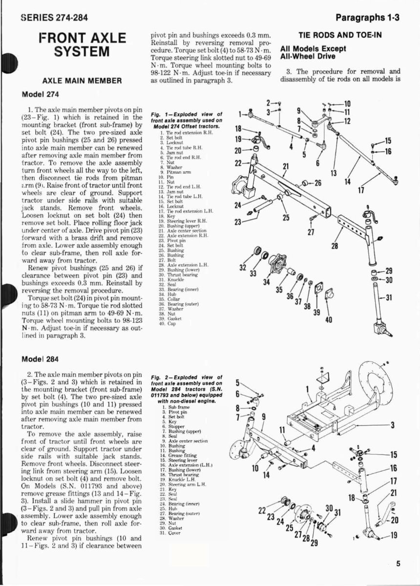
I. The axle main member pivots on pin
(23- Fig. I) which is retained in the
mounting bracket (front. sub-frame) by
set bolt (24). The two pre-sized axle
pivot pin bushings (25 and 26) pressed
l nw axle main member can be renewed
after removing axle main member from
t ractor', To remove the axle assembly
turn front ..... heels all the way to the left.
then dis(.'onnect tic rods from pitman
urn (91. Raise front of tr aclor until front
wheels arc clear of ground. Support
tractor under side rails wi th suitable
jack st.1.nds. Remove front wheels.
Loosen locknut on set bolt (24) then
remove set bolt. Place rolling noor jack
under center of axle. Drive pivot. pin (23)
fo rward with a brass drift and remove
from axle. Lower axle assembly enough
to clear sub-fr.!me, then roll axle for-
ward away from tractor.
Renew pivot bushings (25 and 26) if
clearance between pivot pin (23) and
bushings exceeds 0.3 mm. Reinstall by
reversing the removal procedure.
Torque setbol t(24) in pivot pin mount-
ing to 58-73 N· m. Torque tie rod slotted
nuts (II) on pitman arm to 49-69 N· m.
Torque wheel mounting bolts to 98-1 23
N· m. Adjust toe·in if necessary as out·
lined in parab'Taph 3.
Mode l 284
2. The axle main member pivots on pin
(3- Figs. 2 and 3) which is relained in
the mounting bracket (front sub-frame)
by set bolt (4). The two pre·sized axle
pivot pin bushings (10 and II) pressed
into axle main member can be renewed
after removing axle main member from
tractor.
To remove the axle assembly, rai se
front of tr actor until front wheels are
clt'ar of ground. Support tractor under
side r:iils with suit.able jack stands.
Remove front wheels. Di sconnect ste€r-
jng link from stl.'t'ring arm (15). Loosen
locknul on set boll (4) and remove bolt.
On Model s (S .N. 011793 and above)
remove grease liuings (13 and 14 - Fig.
3). Install a slide hammer in pivot pin
(3 - Fig s. 2 and 3) and ]lull pin from axle
assembly. Lower axle assembly enough
to clear suh-frame. then roll axle for-
ward away from trnctor.
Henew pivot pin bushinl,,>"S (10 and
11 - Figs. 2 and :~) if clearance between
pivot pin and bushings exceeds 0.3 mm.
Reinstall by reversing removal pro--
cedure. Torque set bolt (4) 0058·73 N ·m.
Torque steering link slotted nut to 49·69
N . m. Torque wheel mounting bolts to
98-122 N·m. Adjust toe-in if necessary
as outlined in paragraph 3.
Fit. 1- flfplod.d , 1. 111' 01
Itonl ul ..... mblr lI .. d on
Mod.,274 on .. , tl .eIOrl'.
I. -no rod"~ lUI.
2. Sd bolt
. """,,",
4. Tie rod t~ R.lI.
&. Jam nul
6. Tie rod ~nd R.II .
7. Nut
8 . WaoIwr
9. Pitman ann
LO. Pin
LI. Nul
L2. T~ rOO fro:! 1-11.
13. Jam nul
14. Tie rod tub<> L.II.
If •. Scot bolt
16. Lodmlll
17. Tie rod MI<'f>IIion 1..11 .
18. KfY
19. Sttmng ~ R_H.
20. 8uobine (upptr)
21 Axle ~n~ R't\>On
22. Axle~R.H.
23. PIv<JC •
Paragraphs 1-3
TIE RODS AND TOE-IN
All Models Except
AII·Wheel Drive
3. The procedure for removaJ and
disassembly of tie rods on aJl models is
13
~ 26
14
24. Set:J:"
:u.. ~
~ Bushir«
n. "'"
2:11 • .ult' •• t.o-nsiooo LH .
:29. a..nll(~'
28
3~~
33 3 t:(l;'r@
30. Thrust~
:u. K....-kIo-
"- ,..,
3S. lltannc (in......
34. lIub
"- "'"
36. Bearinc !wI .... '
37. WMho.
38. Nut
" ....
... eo,
Fig. 2_ElIplodH ,I.w 0/
lront ul • .... mbl' "' H on
Mod.1 284 tr,clot' (S.N.
OU7113 end ""0111' , .qlll pptd
III' ltl! non-dl ".'.ngln •.
I. Sub Ir .....
3. Pivot: pin
4. SeI. bNt
:. . K<')'
. . ......
1. llushilllll ("l!Jlt1'1
."""
Y. AU! rmt.-r OKIion
10. 8..ming
II . ButI>in&'
L4. Grnse fittiro«
L5. Slm'i"l '""'
15. AU! '""tmsio ... {LH.1
17. 8uohinl"'"""
18. 'ThnIM .-ariII«
19. li nud<le I_H
2(1. SI.....,~."" I..H.
tl K~)
2:l. So", 1
~l. Sea)
~4 ~v'''' /'n ......
~:,. lIuI,
~7. ~I""h'rl
~. W""""r
:l!I. :->UI
30 G...k.t
al Qr,'(',
5
6 ~
8 -<>
7 9
36
37
I ~
38
39
\
40
~-- 3
5
Paragraphs 4-5 INTERNATIONAL HARVESTER
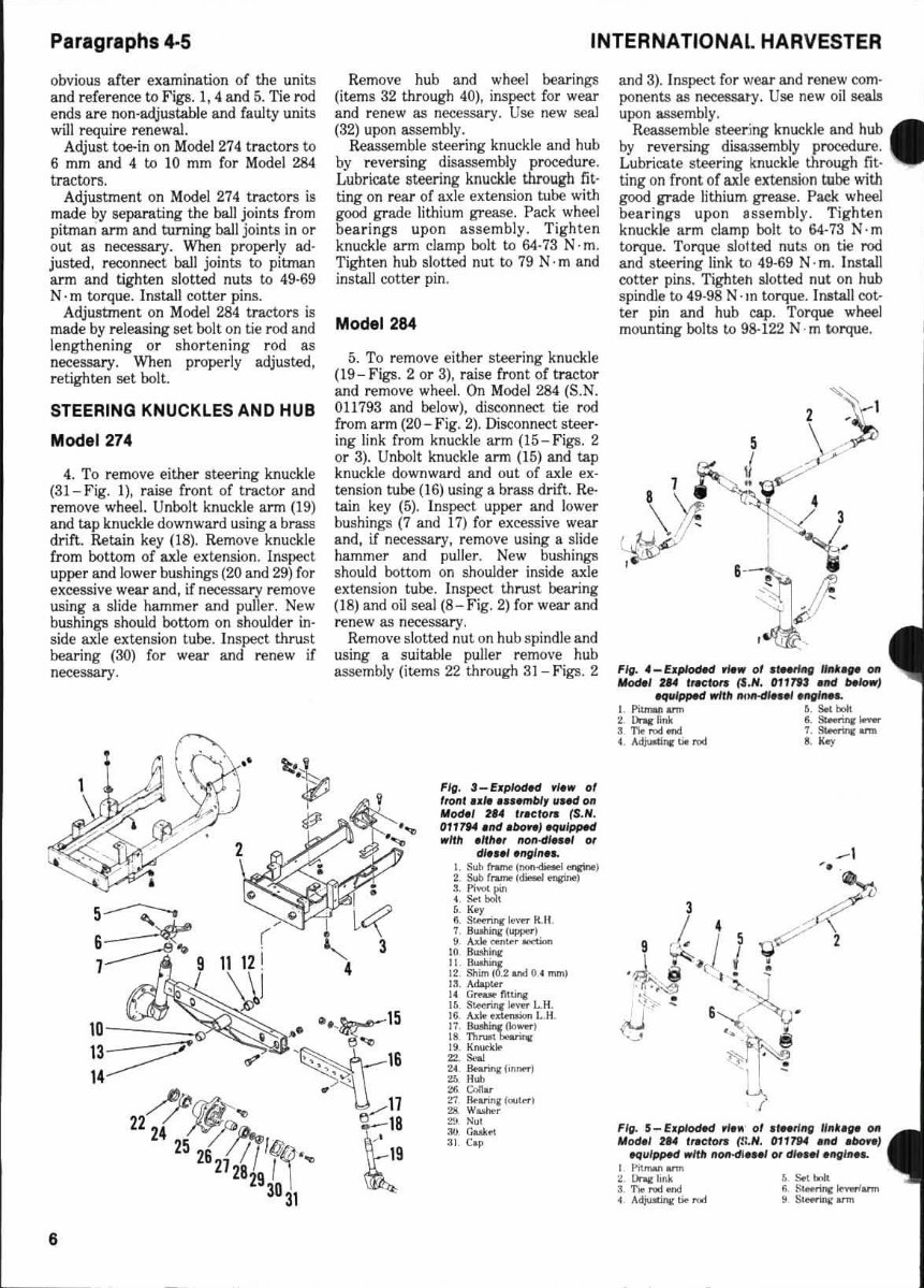
obvious after examination of the units
and reference to Figs. 1,4 and 5. Tie rod
ends are non-adjustable and faulty units
will require renewal.
Adjust toe-in on Model 274 tractors tI:I
6 mm and 4 to 10 mm for Model 284
tractors.
Adjustment on Model 274 tractors is
made by separating the ball joints from
pitman arm and turning ball joints in or
out as necessary. When properl y ad·
justed, reconnect bal l joints to pitman
arm and tighten slotted nuts to 49·69
N· m torque. Install cotter pins.
Adjustment on Model 284 tractors is
made by releasing set bolt on tie rod and
lengthening or shor tening rod as
necessary. When properl y adjusted,
retighten set bolt.
STEERING KNUCKLES AND HUB
Model 274
4. To remove either steering knuckle
(3I-Fig. 1), Taise front of tractor and
remove wheel. Unbolt knuckle arm (19)
and tap knuckle downward using a brass
drift. Retain key (18). Remove knuckle
from bottom of axle extension. Inspect
upper and lower bushings (20 and 29) for
excessive wear and, if necessary remove
usi ng a slide hammer and puller. New
bushings should bottom on shoulder in-
side axle extension tube. Inspect thrust
bearing (30) for wear and renew if
necessary.
Remove hub and wheel bearings
(items 32 through 40) , inspect for wear
and renew as necessary. Use new seal
(32) upon assembly.
Reassemble steering knuckle and hub
by reversing disassembly procedure.
Lubricate steering knuckle through fit-
ting on rear of axle extension tube with
good grade lithium grease. Pack wheel
bea rings up on assembly. Tighten
knuckle arm damp bolt to 64-73 N· m.
Tighten hub slotted nut to 79 N· m and
install cotter pin .
Mod.1264
5. To remove either steering knuckle
(19 - Figs. 2 or 3), raise front of tractor
and remove wheel. On Model 284 (S.N.
0 11 793 and below), disconnect tie rod
from arm (20 - Fig. 2). Disconnect steer·
ing link from knuckle arm (I5-Figs. 2
or 3). Unbolt knuckle ann (15) and tap
knuckle downward and out of axle ex-
tension tube (16) using a brass drift. Re-
tain key (5). Inspect upper and lower
bushings (7 and 17) fo r excessive wear
and, if necessary, remove using a slide
hammer and puller. New bushings
should bottom on should er inside axle
extension tube. Inspect thrust bearing
(I S) and oil seal (8- Fig. 2) for wear and
renew as necessary.
Remove slotted nul on hub spindle and
using a suitable puller remove hub
assembly (items 22 through 31 - Figs. 2
! l cf
'--.,, 3
4
10 •• ,~15
..,.. -"'e:"'tI
13 ~---' '~" 16
14 ------ " ,
~~.. • / 11
22 24 ~?-- ~18
25
26
/ /T'Il(f·~ t 19
21
28
29
1,\ ~
30
31
6
and 3). Inspect for wear and renew com·
ponents as necessary. Use new oil seal!!
upon assembly.
Reassemble steering knuckle and hub
by reversing disassembly procedure.
Lubricate steering knuckle through fit·
ting on front of axle extension tube with
good grade lithium grease. Pack wheel
bearings upon 8ssembly. Tighten
knuckle arm clamp bolt to 64·73 N· m
torque. Torque slot ted nu ts on tie rod
and stee ring link to 49-69 N · m. Install
cotter pins. Tighteh slotted nut on hub
spindle to 49-98 N· In torque. Install cot-
ter pin and hub cap. Torque wheel
mounting bolts to 98-122 N· m torque.
Fig. 4_EJ.pIoded fie,. 0' .lMrlnt IlMi ... 011
",061' , ... ',acton (S. N. 011 7t! .1Id "Jowl
",ulpped ,.11/, IHIft-dle• ., 'II{/III'"
l. PiurwI &ml 5. Sol. ~
2. Dnoe ~nk 6. S&-'nr .......
3_ '!'I."""ond 7. ~ .....
4 Adjuod".. tit r9d 8. K.y
F/rl. 5_ ElCpIodfi/ ~I .. · 01 "Nt/Itg 1I"t. .. 011
MrxHl '14 fraelo,. r.:' N. 0117SN ."d .bore}
~ul~ ..nit IIOII-dl .. " Of dle .. ,.ltglll ...
I 1'iI ........ ann
~ On.r Imk
3 'J)o I"Od ond
4 AdjuoQnj,: tJto ,,'01
~ 5K1roII
GS~~...,.,
~ SIHrlllll &nil
SE RIES 274-284
FRONT SYSTEM
ALL-WHEEL
DRIVE
Model2841raclors equipped with diesel
e nglnel are available n. ·wheel drlye (All ·
Whe. 1 Drive) unlls.
DROP HOUSING ASSEMBLY
AND STEERING KNUCKLE
Models So Equipped
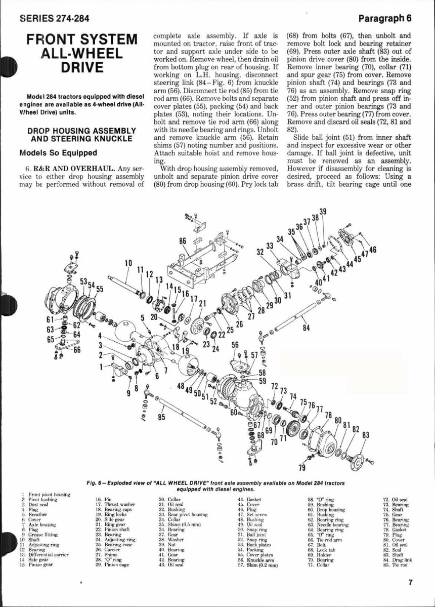
6. R&R AND OVERHA UL. Any se r·
vice to either dr op housing assembly
may be per fo rmed without re moval of
complete axle assembly. LfaxJe is
mounted on tractor, raise front. of trac-
tor and support axle under side to be
worked on . Remove wheel, then drain oil
(rom bottom plug on rear of housing. If
wo rking on L.B. ho usi ng, disconnect
steering link (84 - Fig. 6) from knuckle
arm (56). Disco nnect tie rod (85) from tie
rod arm (66). Remove bolts and separate
cover plates (55), packing (54) and back
plates (53), noting their locations. Un-
bolt and remove tie r od arm (66) along
with its needle bearing and rings. Unbolt
and remove knuckle arm (56). Retain
shims (57) noting number and positions.
Attach suitable hoist and remove hous·
ing.
With drop housi ng assembly removed,
unbolt and separate pinion drive cover
(80) from drop housing (60). Pry l ock tab
ParagraphS
(68) from bolts (67), then unbolt and
remove bolt lock and bearing retainer
(69). Press outer axle shaft (83) out of
pinion drive cover (80) from the inside.
Remove inner beari ng (70), collar (7 1)
and spur gear (75) from cover. Remove
pinion shaft (74) and bearings (73 and
76) as an assembly. Remo ve snap ring
(52) from pinion shaft and press off in·
ne r and outer pinion bearings (73 and
76). Press outer bearing (77) fr om cover.
Remove and discard oil seals (72, 81 and
82).
Slide ball joint (5 1) from inner shaft
and inspect for excessive wear or other
damage. If ball joint is defective, unit
must be rene wed as an assembly.
Howe ve r if disassembly for cleaning is
desired, proceed as foll ows: Using a
brass drifl, tilt bearing cage until one
FI~. 8- E1Iploded ylew 0' - ALL WHEEL DRIVE- 'r01l 181l1e numbly e"ne ble 011 Model 214 '".:10,..
equlp".d WIlli d ln el ell"llIn.
I Fron, piW>! hou$in,o;
2 Pi,-", bushln j/
3 ~,....l
. "~
5 11" .,.1111"
r. (;00.• .".
1 ..... k· hou!Oi'lK
8 Plug
~ Gn· ..... ·fininK
I II Shat,
11 A'ijuAA.!"1! ""K
12 lkarl "ll
I~ PiI(,·,,·I\".1 nnW.
It ~Jto~1IT
15 !"in;"" It"ar
16. I~n
11. Thrusl wWt.-,
18. IlMring •• JlI'
19. RinK k>r.~
20. Si<k·1t"1IT
21. Itin/lW""
22. l"n o»l!!M1l
:1.1. IlearinK
~4. Adj... uinK ring
2',. Il«orinj/ cfII>I'
:!II. C:.r,;..,
n ~hi ....
2lI."O"ril'lj(
:19. F~n""' _
:W. C.~"'r
31 . Oil ot1Il
3'l . HU!lhlnp
33. fk,.., 1''''(>1 ......... ''01
301 . (;t.II",
:1:.. !ihlms In .. ~ mml
3/;. B .... ri l1l
37. r .......
:III. W""","r
:.19. Nu'
~O. U ... nng
41. (...,.,.
42. }\ellJitljf
~~. 0I1..".j
72. OIl 8e~1
'13. 8wing
74 . Shat\
75. Go>a.r
76. Hte.riIII:
77. K, .. arinK
;~. GUIM
;9. 1'1u~
~. C",·tr
~1. Oil "">11
Rt. Sral
83. ~h:on
1!4 . Urnt: link
H~. ')'ioo, rod
7
Paragraphs 7·10
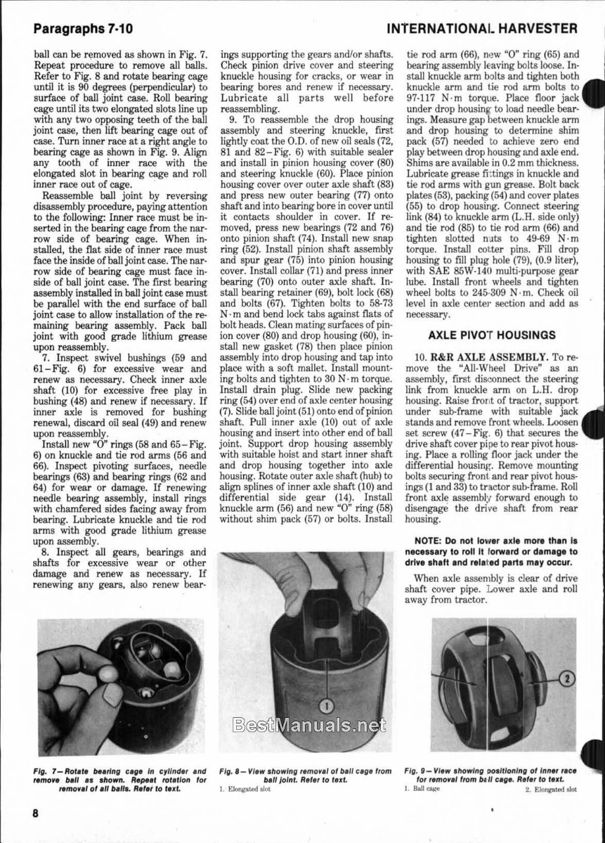
ball can be removed as shown in Fig. 7.
Repeat procedure to remove all balls.
Refer to Fig. 8 and rotate bearing cage
until it is 90 degrees (perpendicular) to
surface of ball joint case. Roll bearing
cage un til its two elongated slots line up
with any two opposing teeth of the ball
joint case, then lift bearing cage out of
case. Turn inner race at a right angle to
bearing cage as shown in Fig. 9. Align
any tooth of inner race with the
el ongated sl ot in bearing cage and roll
inner race out of cage.
Reassemble ball joint by reversing
disassembly procedure, paying attention
to the fo ll owing: Inner race must be in-
serted in the bearing cage from the nar-
row side of bearing cage. When in-
stalled, the flat side of inner race must
face the inside of ball joint case. The nar -
row side of bearing cage must (ace in-
side of ball joint case. The fi r st bearing
assembly installed in ball j oint case must
be parallel with the end surface of ball
joint case to a ll ow installation of the re-
maining bearing assembly. Pack ball
joint with good grad e lithium grease
upon reassembly.
7. Inspect swivel bushings (59 and
61 -Fig. 6) for excessive wear and
renew as necessary. Check inner axle
s haft (10) for excessive free play in
bushing (48) and renew if necessary. If
inner axle is removed for bushing
renewal, discard oil seal (49) and renew
upon reassembly.
Install new "0 " rings (58 and 65- Fig.
6) on knuckle and tie rod arms (56 and
66). Inspect pivoting surfaces, needle
bearings (63) and bearing rings (62 and
64) fo r wear or damage. If renewing
needle bearing assembly, install rings
with chamfered sid es facing away from
bearing. Lubricate knuckl e and tie rod
arms with good grade lithium grease
upon assembl y.
8. Inspect all gears, bearings and
shafts for excessive wear or other
damage and renew as necessary. If
renewing any gears, wso renew bear-
FIg. 7 _ Rol.,. be.rllIg ug. III e,/llId" .lId
... mo" bell ••• hOWII. R,~" ro"tloll 10'
... mo'" 01.11 &.11 •• ""'f 10 lut
8
INTERNATIONAL HARVESTER
ings supporting the gears andlor shafts.
Check pinion dr ive cover and steering
knuckle housing for cracks, or wear in
bearing bores and renew if necessary.
Lubri cate all parts well be fo re
reassembling.
9. To reassemble the drop housi ng
assembly and steer ing knuckle, first
lightly coat the 0 .0 , of new oil seals (72,
81 and 82- F ig. 6) with suitable sewer
and in stall in pinion housing cover (SO)
and steering knuckle (60). Place pinion
housing cover over outer axle shaft (83)
and press new outer bear ing (77) onto
shaft and into bearing bore in cover until
it contacts shoulder in cover. If re-
moved, press new bearings (72 and 76)
onto pinion shaft (74). Install new snap
ring (52). Install pinion shaft assembly
and s pur gear (75) into pinion housing
cover. Install collar (71) and press inner
bearing (70) onto outer axle shaft. In-
stall bearing retainer (69), bolt lock (68)
and bolts (67). Tighten bolts to 58-73
N . m and bend lock tabs against flats of
bolt heads. Clean mating surfaces of pin-
ion cover (80) and drop hous in g (60), in-
stall new gasket (78) then place pinion
assembly into drop housing and tap into
place with a soft mallet. Install mount-
ing bolts and tighten to 30 N· m torque.
Install drain plug. Slide new packing
ring (54) over end of axle center housing
(7). Slide ball joint (51) onto end of pinion
shaft. Pull inner axle (10) out of axle
housing and insert into other end of ball
joint. Suppo rt drop housing assembly
with suitable hoist and start inner shaft
a nd dr op housing together into axle
housing. Rotate outer axle shaft (hub) to
align splines of inner axle shaft (10) and
differential side gear (14). In stall
knuc kl e arm (56) and new ~O" r ing (58)
without shim pack (57) or bolts. Install
FIg.'- VI.w .how/lIg ,.mor.' 01 b.1I e.g. lrom
b./I jolllt. " .,., to lut
I. ~\.Od oIot
ti e rod arm (66), ne w ~O" ring (65) a nd I
bearing assembly leaving bolts loose. In- I
stall knuckle arm bolta and tighten both .
knuckle arm and tie rod arm bolts to
97- 117 N·m torque. Place Doo r jack
under drop housing' to load needle bear-
ings. Measure gap between knuckle arm
and drop housing to determine shim
pack. (57) needed to achieve zero end
play between drop housing and axle end.
Shims are available in 0,2 mm Lhickness.
Lubricate grease fittings in knuckle and
tie rod arms with gun grease. Bolt back
plates (53), packing (54) and cover plates
(55) to drop housing. Connect steering
link (84) to knuckle arm (L.H. side only)
and tie rod (85) to tie rod arm (66) and
tighten slotted nuts to 49-69 N· m
torque. Install colter pins. Fill drop
housing to fill plug hole (79), (0.9 liter ),
with S AE 85W-141l multi·purpose gear
lube. Install front wheels and tighten
wheel bolts to 245-309 N·m. Check oil
level in axle cente.· section and add as
necessary.
AXLE PIVOT HOUSINGS
1 0. R&R AXLE ASSEMBLY. To re-
move the "All· Wheel Drive" as an
assembly, first disconnect the steering
link from knuckle arm on L.H. drop
housing. Rai se front of tractor, s upport
under sul:rframe with suitable jack
stands and remove front wheels. Loosen
set screw (47-Fig. 6) that secures the
drive shaft cover pi pe to rea r pivot hous-
i ng. Place a ro lli ng floor jack under the
differential housinf~. Remove mounting
bolts securing front and rear pivot bous·
ings( 1 and 33) to tractor sub-frame. Roll
front axl~ assembly forward enough to
disengage the dri ve shaft from rear
hous ing.
NOTE: Do not low.r exl. more thin I.
nec .... ry to roll II / orwud or dlmlge to
drlv •• hllt Ind r.tl t.d Plrt. may occur.
When axle assembly is clear of drive
shaft cover pipe. Lower axle and roll
away from tractor.
F/g. 8_ VI ... • how/lIg PO.lllolllllg 01 In n., ,.e.
for ,.mor.,lrom bill ctg • . " .,,, 10 lu' .
I. Ball can 2. EIMp\.Od oIot
SERIES 274·284
Insu..nation of axle assembly is the
reverso! of removal procedure. Lightly
coat sl ,li nes of drive shaft. and coupling
•
fik'eve~ with Molykote lubricant. Apply
Loctit{ 1262 or equivalent to thr eads of
IIXle mounting bolts. Torque mounting
I:olts to 244 ·307 N· m. Torque slotted
rut 011 sleering link to 49·69 N· m.
Torque fronl wheel mounting bolts to
245·30~) N ·m.
II. R&R AND OVERHAUL PfVQT
JIOUS.l NGS. Service of the front and
r2ar pi vot housings (1 a nd 33 - Fig. 6) reo
<Iuires removal of the comple te axle
assemtly as outlined in paragraph 1 0.
SCrviCf of the front housing is limited to
r ~placemenl of the dust seal (3) and
bushinl[ (2).
NOTI:: Rlmo .... 1 01 grea •• IIIlIng may be
necessary tor (emoul of !tont pivot
bu.hln, •.
Whcli replacing (ront pivot bushing,
line up hole in bushing with grease fit-
ting hole. Always install new dust seal.
Lubri cE.te bushing wi th multi·purpose
Ii :.hium grease.
To I 'e move rear p ivot housing
(~.3 - FiJ. 6) first drain center housing (7)
a 1d remove bolts from housing cover
(~5), then using two of the bolts, turn
tllem hto jackscrew hol es on cover.
Turn b)lts evenly to push cover Crom
h' lUsi n!! . Discard gasket (4 4). Using a
bl 1l.SS dl-ift, tap gear and bearings (items
4t), 41 and 42) (rom cover (45). Inspect
g'~nr Imd bea rings and renew iJ
nl!<!essa ry. Remove and discard oil seal
(43). Rpm ovl! housing oil seal (3 1) and
drive out bushing (32). Drive in new
bushing and install new oi l seal. Press
la rge lwaring (42) onto input shaft side
01' gear (41) and small bearing (40) onto
hnus ing side of gear. Tap bearing and
gl: ar as.;embly into bore of housing. I n-
:itall ne'N oil seal (43) and cover gas ket
144). th~'n bol t on cover (45) to housing
l3l). Fi I center housing (5) to fillllevel
10 -I'I.w tllowl n" P'OC~Il'. 10' ell.dlng
prffol d 01 pInIon b", 'n" . A.I., Ig lUI.
I :;"rillll: "" ....
2 ' ''1.. 3. 1'1.",
plug (4), (2.7 liters), with SAE 86W- 140
multi·purpose gear lube.
DIFFERENTIAL
12. R&R AND OVERHAUL. To re-
move the differential assembly for ser-
vice, first remove axle assem bl y as
out lined in paragraph 10 , then remove
dr op housing assemblies as out lined in
paragraph 6. Remove front and rear
pivot housings as outlined in paragraph
11 . Pull both axle shafts (I O- Fig. 6) out
of axle housing. Remove pinion cage (29)
mounting bolts , then using two of the
bolts, turn them into the jackscrew holes
on flange of cage. Tum bolts evenly and
push pinion cage (29) from car rier
assembly (26). Retain shims (27) and
discard "0" ring (28). Attach lifting
brackets and a suitable hoist to the dif-
ferential carrier assembly (26). Remove
bolts and lift carrier assembly out of axle
housing. Flatten tabs on ring locks ( 19)
and remove. Unbolt and remove bearing
caps (1 8).
NOTE: B •• rlng e.p •• hould b. Ind.xitd
lor eorr.cl r ..... mbly .
Remove bearing adjusting rings (1 1
and 24 ) and lift differential carrier
asse mbly out of housi ng. Unbolt and
separate r ing gea r (2 1) from carrier (13)
using a soft hammer. Remove side gear
(20) and thrust washer (17) from ring
gear recess. Remove ring gear bearing
(23) using a suitable puller. Remove pin
retaining screw in differential carrier
(13), then drive out p in (16) and remove
s id e and pinion gears (14 and J5).
Remove differential carrier bearing (1 2)
using a suitable puller.
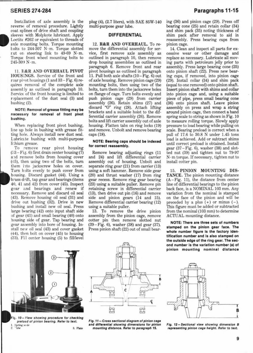
13. To remove the drive pinion
assembly from the pinion cage, remove
cotter pin then remove slotted nu t
(39 - Fig. 6), was her (38) and gear (37).
Press pin ion sha ft (22) out of small bear-
A
d .
L
Ii'"
~
•
,j,
,
•
""
'c
,
IT J
FI" . 11- Cro .. tKllfnI.' dl.",.m g/ pfnkln u".
.tId dlll.,.nl l.1 . 1I0wl n" dlm.n,Ion, 10' pinI on
mOllnlln" dl. l.ne • . 1f., ,, 10 ptr ."rtptt 15.
Paragraphs 11·15
ing (36) and pinion cage (29). Press off
bearing cone (25) and retain coll ar (34)
and shim pack (35) noting thickness of
shim pack after removal to aid in
reassembly. Press bearing cups Crom
pini on cage.
14. Clean and inspect all part3 (o r ex·
cessive wear or o ther damage and
replace as necessary. Lubricate all mov·
ing parts with petroleum jelly prior to
assembly. Press large bearing cone (25)
onto pinion shaft (22). Press new hear-
ing cups, if removed, into p in io n cage
(29). Install collar (34) and sh im pack
(equal to one removed) onto pinion shaft.
Insert pinion shaft with shims and collar
into pini on cage and, using a suitable
piece of pipe, press small bearing cone
(36) onto pinion shafl Leave pinion
assembly on press and wrap a stri ng
around pinion cage, then connect a hand
spring scale to string as shown in Fig. 10
to measure rolling torque. Slowly app ly
pressure to load bearing while pulling on
scale. Bearing preload is correct when a
pull of 17.6 to 30.8 N under 1.45 tons
load is achieved. Add or subtract s him s
until co rr e<:t preload is obtained~ Install
gear (37-Fig. 6), washer (38) and slot,..
ted nut (39) and tighten nut to 79-97
N· m torque. U necessary, tighten nut to
install cotter pin.
15. PI NION MO UNT ING DIS-
TANCE. The pinion mounting distance
(A- Fig. 11 ), the distance from center
line of differential bearings to the pi nion
back face, is a NOM INAL 103 mm. Any
variation from the nominal is stamped
on the face of the pinion and will be
preceded by a plus (+) or mi nus (-).
This figure must be added or subt racted
from the nominal (103 mm) to determine
ACTUAL mounting di s ta nce.
NOTE: There .r. Ihr ••• els 01 numbe.-.
slamped on Ih. pinion g •• r I.e •. Th.
whol. number IIgur. I. thl Iletory Iden·
tIIle.tlon number and I •• 110 atamped on
the outlld. edge 01 the ring gelr. Th. ,.c,
ond number Is the v.rl.tlon number (.) 01
pinion mounting nomln.1 dllt.ne.
L
Fig. 12 -SKtion.' ,I .w t ll o wln " dlm.ntlon 8
r.pr".nlln" p inion u". ".1",,1. 1f. I" 10 I • ., .
9
Paragraphs 16-17
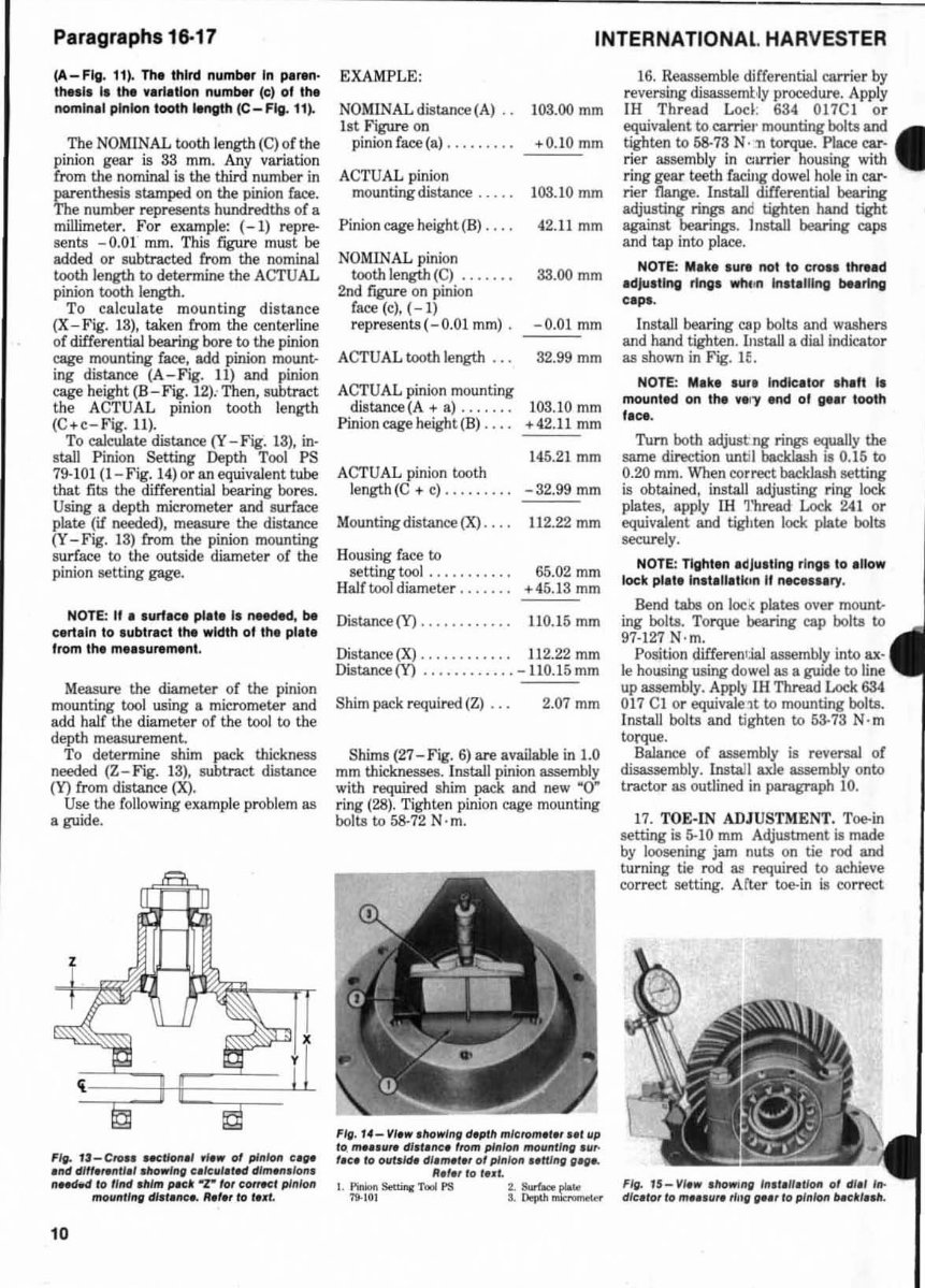
(A-Fig . 11). The third number In perin·
Itt .. ,. I, 1M "'In,tlon number (el 01 the
nomln.1 pinion tooth length (e - F~. 11).
The NOMI NAL tooth length (C) of the
pinion gear is 33 mm. Any variation
from the nominal is the third number in
parenthesis stamped on the pinion face.
The number represents hundredths of a
millimeter. For example: (- 1) repre-
sents -0.01 mm. This figure must be
added or subtracted from the nominal
tooth length to determine the ACTUAL
pinion tooth length.
To cal culate mounting distance
(X - Fig. 13), taken from the centerline
of differential bearing bore to the pinion
cage mounting face. add pinion mount-
ing dista~ (A - Fig. 11) and pinion
cage height (B - Fig. 12): Then, subtract
the ACTUAL pinion tooth length
(C+c-Fig. 11 ).
To ca1culate distance (Y - Fig. 1 3), in-
stall Pinion Setting Depth Tool PS
79-101 (1 - Fig. 14) or an equivalent tube
that fits the differential bearing bores.
Using a depth micrometer and surface
plate (if needed), measure the distance
(Y -Fig. 13) from the pinion mounting
surface to the ou tside diameter of the
pinion setting gage.
NOTE: If • luri.ce pl.le II needed, be
cert.ln to lublr.ct Ihe width of the pl.le
from the m ... ur.ment.
Measure the diameter of the pinion
mounting tool using a micrometer and
add half the diameter of the tool to the
depth measurement.
To determine shim pack thickness
needed (Z- Fig. 13). subtract distance
(Y) from distance 00.
Use the following example probl em as
a guide.
Fit . U -Cro .. ueUon.' NW 01 pI"lon CI.,.
.1Id dltt .... nll.,.howfn ll f:./f:ul.," dl m.". lo".
nHCWd to lind . hlm pglr 'T' 101 f:QnWCf pinion
mov"I1,,'1 dl.f.nf: •. It.,., 10 I.,d.
10
INTERNATIONAl. HARVESTER
NOMI NAL distance (A) .. 103.00 mm
1 st Figure on
pinion face (a) ......... +0.10 mm
ACTUAL pinion
mounting distance ..... 103.10 mm
Pinion cage height(B) . . . . 42.11 mm
NOMINAL pinion
tooth length (C) ....... 33.00 mm
2nd figure on pinion
r ... (,),(-I)
represen ts( - O.OI mm) . -0.01 mm
ACTUAL tooth length. . . 32.99 mm
ACTUAL pinion mounting
distance (A + a) . . . . . . . 103.10 mm
Pinion cage height (B) .... +42. 11 mm
145.21 mm
ACTUAL pinion tooth
length(C + c) ......... - 32.99 mm
Mounting distance (X) . . .. 112.22 mm
Housing face to
setting tool . . . . . . . . . . . 65.02 mm
Half tool diameter ....... +45.13 mm
Distance(¥) ............ 110.15 mm
Distance (X) .... • ....... 112.22 mm
Distance(¥) .. . ......... -1l0.15mm
Shim pack required (Z) ... 2.07 mm
Shims (27-Fig. 6) are available in 1.0
mm thicknesses. Install pinion assembly
with required shim pack and new "O~
ring (28). Tighten pinion cage mounting
bolts to 58-72 N · m.
"II . '4- VI.w .lIow''''1 d.plll mlclQIII.III .1t lip
to. m ... u... dl.I .nf:. f rom pinion mou"tl"'1'U,,
I.c. /0 OIll,Id. dl.mI'" 01 p1" Io" .. lIlnllll"'''
It.I., 10 I .... .
I. Pinion Settillj( Tool PS 2. SurlJo::e plaw
79-10 1 3. ~ mim>Inet«
16. Reassemble differential camer by
reversing disassembly procedure. Apply
IH Thread Lod : 684 017C I or
equivalent to carriel' mounting bolts and •
tighten to 5&-73 N· n torque. Place car ·
rier assembly in camer housing with
ring gear teeth facing dowel hole in ear-
rier !lange. Install differential bearing
adjusting rings and tighten hand tight
against bearings. Jnstall bearing caps
and tap into place.
NOTE: Mlk. lure not to CIO .. th,e. d
.djuiling Ilngl whim Inlt.lllng beerlng
C.pl.
Install bearing cap bolts and washers
and hand tighten. J..IlstaU a dial indicator
as shown in Fig. JE.
NOTE: M.ke .Utl I ndk.tor Ih.ft II
mounltd on the veJ OY .nd 01 g'.' tooth
f.c •.
Tum both adjustng rings equally the
same direction until backlash is 0.15 to
0.20 mm. When correct backlash setting
is obtained. install adjusting ring lock
plates, apply lH 1'hread Lock 241 or
equivalent and tigllten lock plate bolts
securely.
NOTE: Tlght.n edlultlng rlngl to . lIow
lock pl.te Inlt.llltkin II nee .... ".
Bend tabs on loc .( plates over mount.-
ing bolts. Torque beating cap bolts to
97-127 N · m.
Position differential assembly into ax-
le housing using dowel as a guide to line
up assembly. Appl)' IH Thread Lock 6S4
0 17 CI or equivale1t. to mounting bolts.
Install bolts and tighten to 53-73 N·m
torque.
Balance of assembly is reversal of
disassembly. Install axle assembly onto
tractor as out lined in paragraph 10.
1 7. TOE-IN ADJUSTMENT. Toe-in
setting is &-10 mm Adjustment is made
by loosening jam nuUl on tie rod and
turning t ie rod as required to achieve
correct setting. After toe-in is correct
Fit. TS - Vllw .lIow",'1 In,t.lI.tloft 01 d l./ lit-
dlf:llot'O mll , ur. rill , tN' 10 pI"lon o.ct/ .. II.
You're Reading a Preview
What's Included?
Fast Download Speeds
Online & Offline Access
Access PDF Contents & Bookmarks
Full Search Facility
Print one or all pages of your manual
$41.99
Viewed 75 Times Today


Secure transaction
What's Included?
Fast Download Speeds
Online & Offline Access
Access PDF Contents & Bookmarks
Full Search Facility
Print one or all pages of your manual
$41.99
Thank you for considering this comprehensive Service Repair Workshop Manual for the Case IH 284 Tractor.
This manual is an invaluable resource covering every Service & Repair Procedure, designed to save you significant costs by enabling you to perform your own repairs. It provides easy-to-follow, step-by-step instructions and detailed illustrations for all servicing and repairs.
Upon acquisition, this manual becomes your permanent asset, allowing you to print individual pages, chapters, or the entire manual. It is also compatible for viewing on tablets and smartphones.
MODELS COVERED:
- All Models/Engines/Trim/Transmissions Types Are Covered.
CONTENTS:
- This high-quality Service Repair Workshop Manual encompasses all repair procedures from A to Z, ensuring comprehensive coverage of every repair and service procedure.
COMPUTER REQUIREMENTS:
- This manual is compatible with all PC & MAC Computers, tablets, and mobile phones. It only requires adobe reader, which is typically pre-installed on most computers or can be downloaded for free.
DELIVERY:
- Upon payment via Visa, MasterCard, or PayPal, the manual will be instantly emailed to the address provided during checkout.
Customer Satisfaction Guaranteed.


