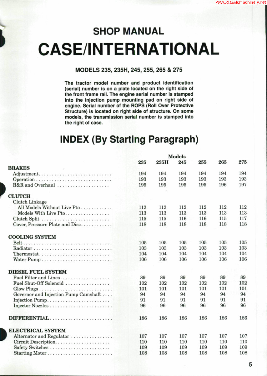
SHOP MANUAL CASE/INTERNATIONAL MODELS 235, 235H, 245, 255, 265 & 275 The tractor model number and product identification (seriai) number is on a plate iocated on the right side of the front frame raii. The engine seriai number is stamped into the injection pump mounting pad on right side of engine. Serial number of the ROPS (Roii Over Protective Structure) is iocated on right side of structure. On some modeis, the transmission seriai number is stamped into the right of case. INDEX (By Starting Paragraph) BRAKES Adjustment Operation R&R and Overhaul CLUTCH Clutch Linkage All Models Without Live Pto Models Witli Live Pto Clutch Split Cover, Pressure Plate and Disc COOLING SYSITEM Belt Radiator Thermostat Water Pump DIESEL FUEL SYSTEM Fuel Filter and Lines Fuel Shut-Off Solenoid Glow Plugs Grovemor and Injection Pump Camshaft Injection Pump Injector Nozzles DIFFERENTLSkL ELECTRICAL SYSTEM Alternator and Regulator Circuit Description Safety Switches Starting Motor 235 194 193 195 112 113 115 118 105 103 104 106 89 102 101 94 91 96 Models 235H 194 193 195 112 113 115 118 105 103 104 106 89 102 101 94 91 96 245 194 193 195 112 113 116 118 105 103 104 106 89 102 101 94 91 96 255 194 193 195 112 113 116 118 105 103 104 106 89 102 101 94 91 96 265 194 193 196 112 113 115 118 105 103 104 106 89 102 101 94 91 96 275 194 193 197 112 113 117 118 105 103 104 106 89 102 101 94 91 96 186 186 186 186 186 186 107 110 109 108 107 110 109 108 107 110 109 108 107 110 109 108 107 110 109 108 107 110 109 108
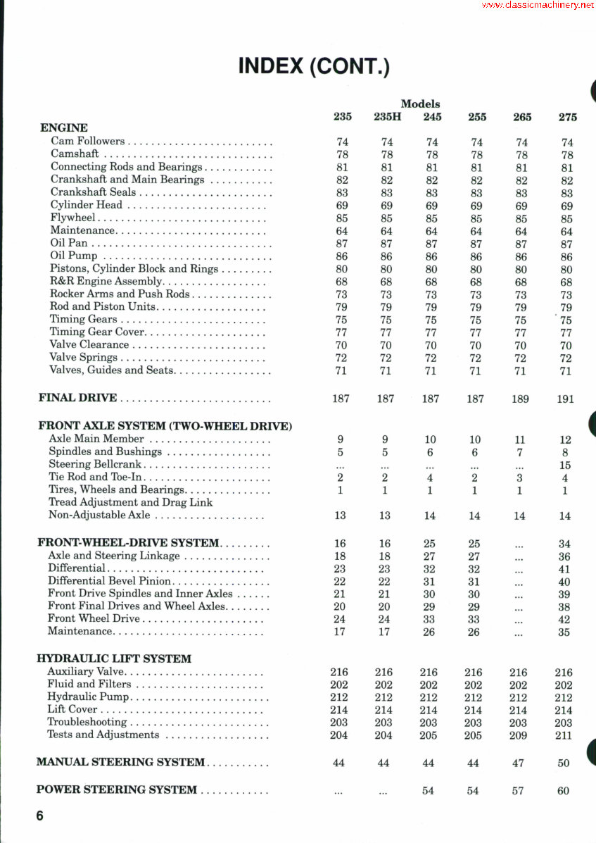
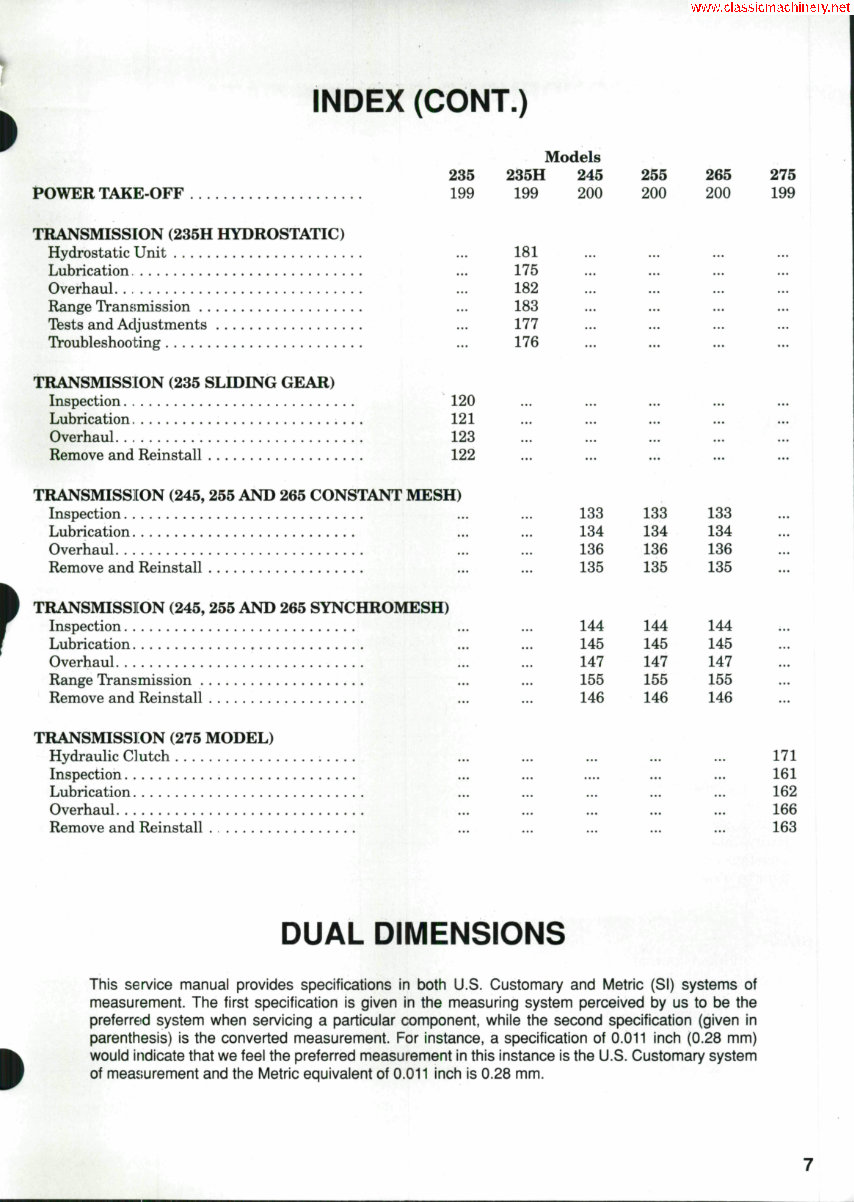
INDEX (CONT.) 235 POWER TAKE OFF 199 TRANSMISSION (235H HYDROSTATIC) Hydrostatic Unit Lubrication. Overhaul Range Transmission Tests and Adjustments Troubleshooting TRANSMISSION (235 SLIDING GEAR) Inspection 120 Lubrication 121 Overhaul 123 Remove and Reinstall 122 TRANSMISSION (245, 255 AND 265 CONSTANT MESH) Inspection Lubrication Overhaul Remove and Reinstall TRANSMISSllON (245, 255 AND 265 SYNCHROMESH) Inspection Lubrication Overhaul Range Transmission Remove and Reinstall TRANSMISSl ON (275 MODEL) Hydraulic Clutch Inspection Lubrication Overhaul Remove and Reinstall . Models 235H 199 181 175 182 183 177 176 245 200 ... • .* ... ... 255 200 ... ... ... 265 200 ... ... 275 199 ... ... ... 133 134 136 135 144 145 147 155 146 .... ... ... 133 134 136 135 144 145 147 155 146 ... ... ... 133 134 136 135 144 145 147 155 146 ... ... ... ... ... ... ... ... 171 161 162 166 163 DUAL DIMENSIONS This service manual provides specifications in both U.S. Customary and Metric (SI) systems of measurement. The first specification is given in the measuring system perceived by us to be the preferred system when servicing a particular component, while the second specification (given in parenthesis) is the converted measurement. For instance, a specification of 0.011 inch (0.28 mm) would indicate that we feel the preferred measurement in this instance is the U.S. Customary system of measiurement and the Metric equivalent of 0.011 inch is 0.28 mm.
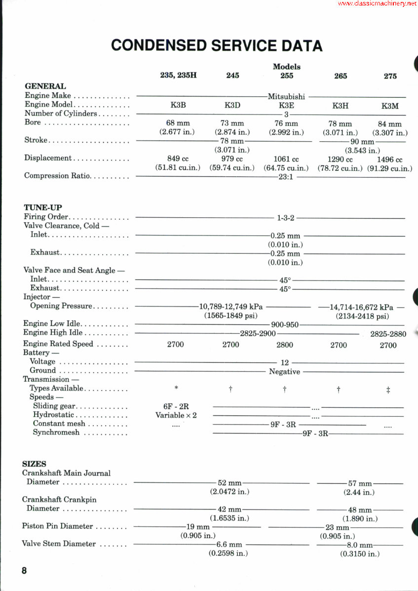
CONDENSED SERVICE DATA 235, 235H 245 GENERAL Engine Make Engine Model Number of Cylinders Bore Stroke Displacement Compression Ratio TXJNE-UP Firing Order Valve Clearance, Cold — Inlet Exhaust Valve Face and Seat Angle Inlet Exhaust Injector — Opening Pressure Engine Low Idle Engine High Idle Engine Rated Speed Battery — Voltage Ground Transmission — Types Available Speeds — Sliding gear , Hydrostatic , Constant mesh S3nic SIZES Crankshaft Main Journal Diameter Crankshaft Crankpin Diameter Piston Pin Diameter Valve Stem Diameter K3B K3D Models 255 -Mitsubishi K3E 3 265 275 i K3H K3M 68 mm (2.677 in.) 73 mm (2.874 in.) — 78 mm— 76 mm (2.992 in.) 78 mm 84 mm (3.071 in.) (3.307 in.) 90 mm (3.071 in.) (3.543 in.) 849 cc 979 cc 1061 cc 1290 cc 1496 cc (51.81 cu.in.) (59.74 cu.in.) (64.75 cu.in.) (78.72 cu.in.) (91.29 cu.in.) 23:1 1-3-2 -0.25 mm - (0.010 in.) -0.25 mm - (0.010 in.) 45° 45° -10,789-12,749 kPa (1565-1849 psi) 900-950- —14,714-16,672 kPa — (2134-2418 psi) i -2825-2900- 2700 2700 2800 2700 2825-2880 2700 12 Negative t 6F-2R Variable x 2 -9F-3R -9F - 3R- -52 mm- (2.0472 in.) — 57 mm— (2.44 in.) 42 mm- (1.6535 in.) —19 mm — (0.905 in.) 48 mm — (1.890 in.) 23 mm —6.6 mm - (0.2598 in.) (0.905 in.) 8.0 mm- (0.3150 in.) 8
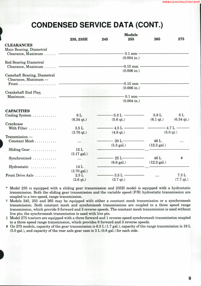
CONDENSED SERVICE DATA (CONT.) CLEARANCES Main Bearing, Diametral Clearance, Miiximum Rod Bearing D iametral Clearance, Miaximum Camshaft Bearing, Diametral Clearance, Maximum — Front Crankshaft End Play, Maximum CAPACITIES Cooling System Crankcase With Filter Transmission — Constant Mesh Sliding Gear Synchronized Hydrostatic Front Drive Axle 235,235H 6L (6.34 qt.) 3.5 L (3.70 qt.) 12 L (3.17 gal.) 14 L (3.70 gal.) 2.5 L (2.6 qt.) 245 Models 255 265 275 - 0.1 mm — (0.004 in.) —0.15 mm - (0.006 in.) —0.15 mm - (0.006 in.) — 0.1 mm — (0.004 in.) -5.3 L - (5.6 qt.) - 4.5 L - (4.8 qt.) 20 L- (5.3 gal.) 25 L- (6.6 gal.) -3.5L- (3.7 qt.) 5.8 (6.1 ( 46 (12.2 46 (12.2 L qt.) (5 L gal.) L gal.) 1 7 t, 1 .0 (6 qt.) 6L .34 qt.) # 7.3 L (7.7 qt.) * Model 235 is equipped with a sliding gear transmission and 235H model is equipped with a hydrostatic transmission. Both the sliding gear transmission and the variable speed (F/R) hydrostatic transmission are coupled to a two speed, range transmission. t Models 245, 255 and 265 may be equipped with either a constant mesh transmission or a synchromesh transmission. Both constant mesh and synchromesh transmissions are coupled to a three speed range transmission, which provide 9 forward and 3 reverse speeds. The constant mesh trguismission is used without live pto; the synchromesh transmission is used with live pto. t Model 275 tractors are equipped with a three forward and 1 reverse speed S3nichromesh transmission coupled to a three speed range transmission, which provides 9 forward and 3 reverse speeds. # On 275 models, capacity of the gear transmission is 6.5 L (1.7 gal.), capacity of the range transmission is 19 L (5.0 gal.), and capacity of the rear axle gear case is 3 L (0.8 gal.) for each side. 9
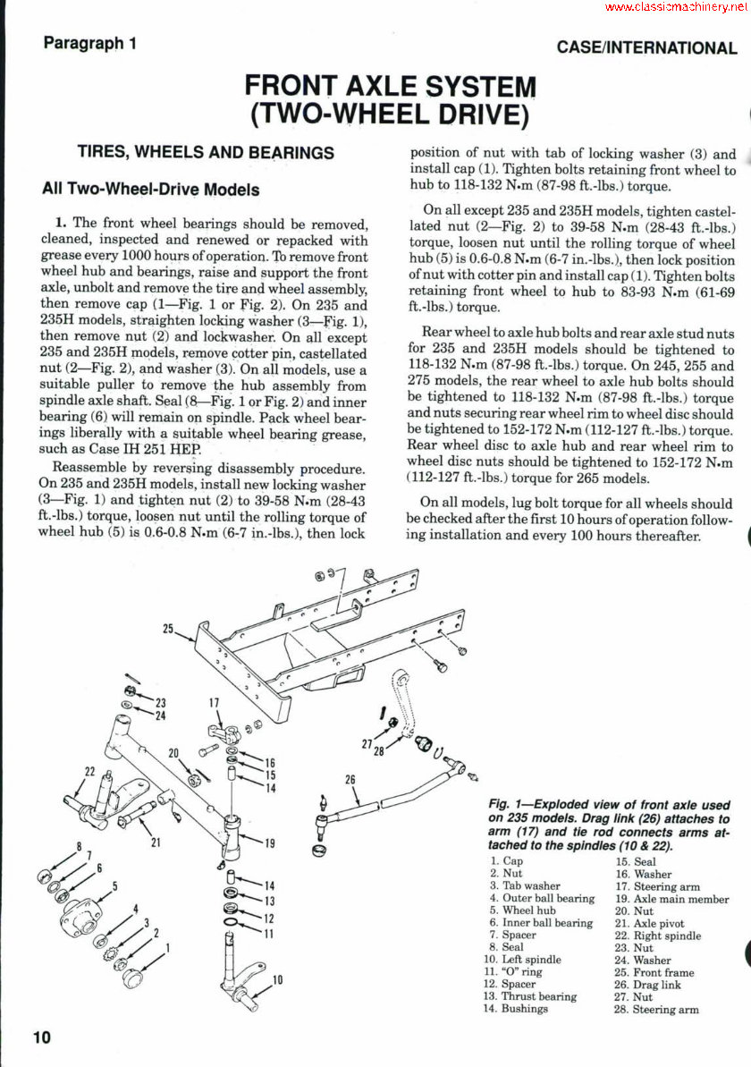
Paragraph 1 CASE/INTERNATIONAL FRONT AXLE SYSTEM (TWO-WHEEL DRIVE) TIRES, WHEELS AND BEARINGS All Two-Wheel-Drive Models 1, The front wheel bearings should be removed, cleaned, inspected and renewed or repacked with grease every 1000 hours of operation. % remove front wheel hub and bearings, raise and support the front axle, unbolt and remove the tire and wheel assembly, then remove cap (1—Fig. 1 or Fig. 2). On 235 and 235H models, straighten locking washer (3—Fig. 1), then remove nut (2) and lockwasher. On all except 235 and 235H niodels, reinove cotter pin, castellated nut (2—Fig. 2), and washer (3). On all models, use a suitable puller to remove t;he hub assembly from spindle axle shaft. Seal (3—Fig. 1 or Fig. 2) and inner bearing (6) will remain on spindle. Pack wheel bear- ings liberally with a suitable wheel bearing grease, such as Case IH 25 X HEP. Reassemble by reversing disassembly procedure. On 235 and 235H models, install new locking washer (3—Fig. 1) and tighten nut (2) to 39-58 N.m (28-43 ft.-lbs.) torque, loosen nut until the rolling torque of wheel hub (5) is 0.6-0.8 N.m (6-7 in.-lbs.), then lock position of nut with tab of locking washer (3) and install cap (1). Tighten bolts retaining front wheel to hub to 118-132 N.m (87-98 ft.-lbs.) torque. On all except 235 and 235H models, tighten castel- lated nut (2—Fig. 2) to 39-58 N.m (28-43 ft.-lbs.) torque, loosen nut until the rolling torque of wheel hub (5) is 0.6-0.8 N.m (6-7 in.-lbs.), then lock position of nut with cotter pin and install cap (1). Tighten bolts retaining front wheel to hub to 83-93 N.m (61-69 ft.-lbs.) torque. Rear wheel to axle hub bolts and rear axle stud nuts for 235 and 235H models should he tightened to 118-132 N.m (87-98 ft.-lhs.) torque. On 245, 255 and 275 models, the rear wheel to axle huh bolts should be tightened to 118-132 N.m (87-98 fb.-lbs.) torque and nuts securing rear wheel rim to wheel disc should he tightened to 152-172 N.m (112-127 ft.-lhs.) torque. Rear wheel disc to axle huh and rear wheel rim to wheel disc nuts should be tightened to 152-172 N.m (112-127 fb.-lbs.) torque for 265 models. On all models, lug bolt torque for all wheels should be checked after the first 10 hours of operation follow- ing installation and every 100 hours thereafter. | 25 Fig. I^Exploded view of front axie used on 235 models. Drag lini( (26) attaches to arm (17) and tie rod connects arms at- tached to tiie spindies (10 & 22). 1. Cap 2. Nut 3. Tab washer 4. Outer ball bearing 5. Wheel hub 6. Inner ball bearing 7. Spacer 8. Seal 10. Left spindle 11. "O" ring 12. Spacer 13. Thrust bearing 14. Bushings 15. Seal 16. Washer 17. Steering arm 19. Axle main member 20. Nut 21. Axle pivot 22. Right spindle 23. Nut 24. Washer 25. Front frame 26. Drag link 27. Nut 28. Steering arm 10
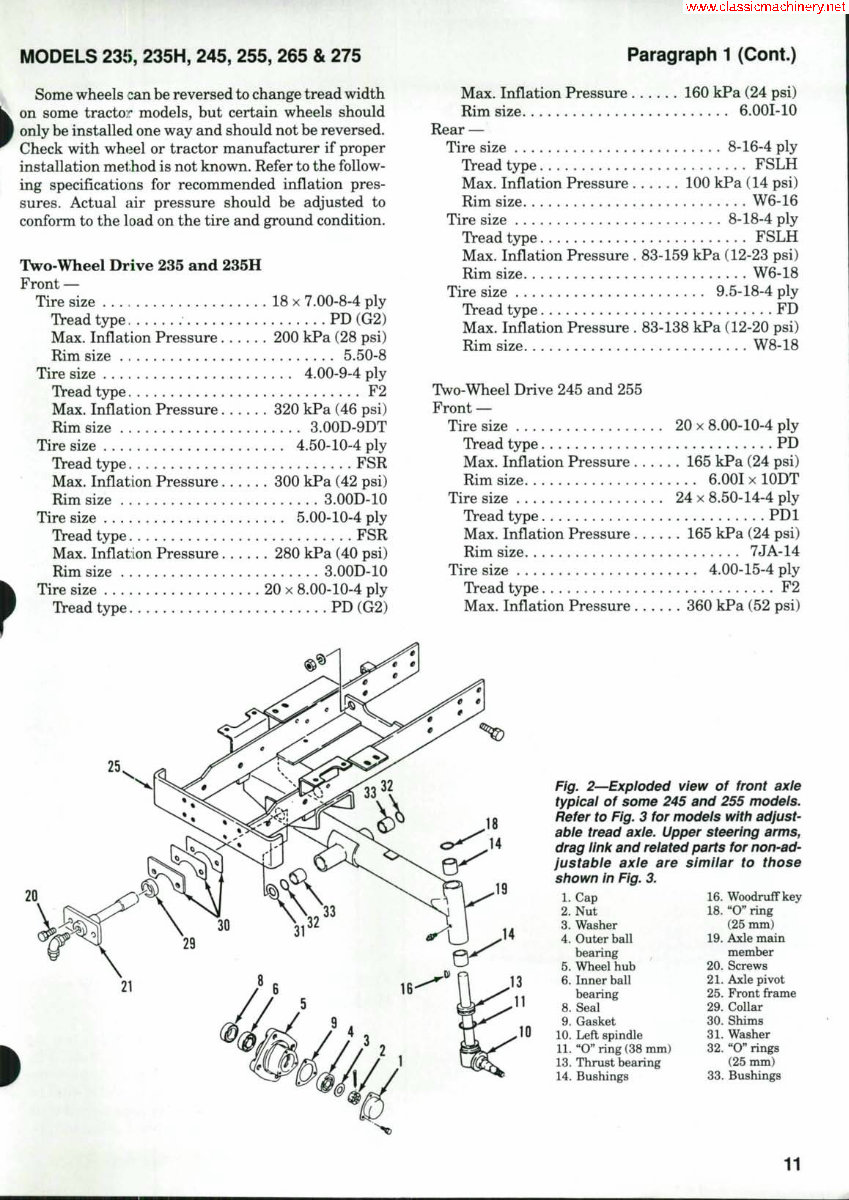
MODELS 23j>, 235H, 245, 255, 265 & 275 Paragraph 1 (Cont.) Some wheels can be reversed to change tread width on some tracto]r models, but certain wheels should only be installed one way and should not be reversed. Check with wheel or tractor manufacturer if proper installation method is not known. Refer to the follow- ing specifications for recommended inflation pres- sures. Actual air pressure should be adjusted to conform to the load on the tire and ground condition. Two-Wheel Drive 235 and 235H Front — Tire size 18 x 7.00-8-4 ply Tread type PD (G2) Max. Inflation Pressure 200 kPa (28 psi) Rim size 5.50-8 Tire size 4.00-9-4 ply Tread type F2 Max. Inflation Pressure 320 kPa (46 psi) Rim size 3.00D-9DT Tire size 4.50-10-4 ply Tread type FSR Max. Inflation Pressure 300 kPa (42 psi) Rim size 3.00D-10 Tire size 5.00-10-4 ply Tread type FSR Max. Inflation Pressure 280 kPa (40 psi) Rim size 3.00D-10 Tire size 20 x 8.00-10-4 ply Tread type . . . PD (G2) Max. Inflation Pressure 160 kPa (24 psi) Rim size 6.001-10 Rear — Tire size 8-16-4 ply Tread type FSLH Max. Inflation Pressure 100 kPa (14 psi) Rim size W6-16 Tire size 8-18-4 ply Tread type FSLH Max. Inflation Pressure . 83-159 kPa (12-23 psi) Rim size W6-18 Tire size 9.5-18-4 ply Tread type FD Max. Inflation Pressure . 83-138 kPa (12-20 psi) Rim size W8-18 Two-Wheel Drive 245 and 255 Front — Tire size 20 x 8.00-10-4 ply Tread type PD Max. Inflation Pressure 165 kPa (24 psi) Rim size 6.001 x lODT Tire size 24 x 8.50-14-4 ply TVead type PDl Max. Inflation Pressure 165 kPa (24 psi) Rim size 7JA-14 Tire size 4.00-15-4 ply Tread type F2 Max. Inflation Pressure 360 kPa (52 psi) 25 Fig. 2—Exploded view of front axie typicai of some 245 and 255 modeis. Refer to Fig. 3 for modeis witti adjust- abie tread axie. Upper steering arms, drag iinii and reiated parts for non-ad- Justabie axie are simiiar to those siiown in Fig. 3. 16. Woodruff key 18. "O" ring (25 mm) 19. Axle main member 20. Screws 21. Axle pivot 25. Front frame 29. Collar 30. Shims 31. Washer 32. "O" rings (25 mm) 1. Cap 2. Nut 3. Washer 4. Outer ball bearing ^ 5. Wheel hub 6. Inner ball bearing 8. Seal 9. Gasket 10. Left spindle 11. "Cring (38 mm) 13. Thrust bearing 14. Bushings 33. Bushings 11
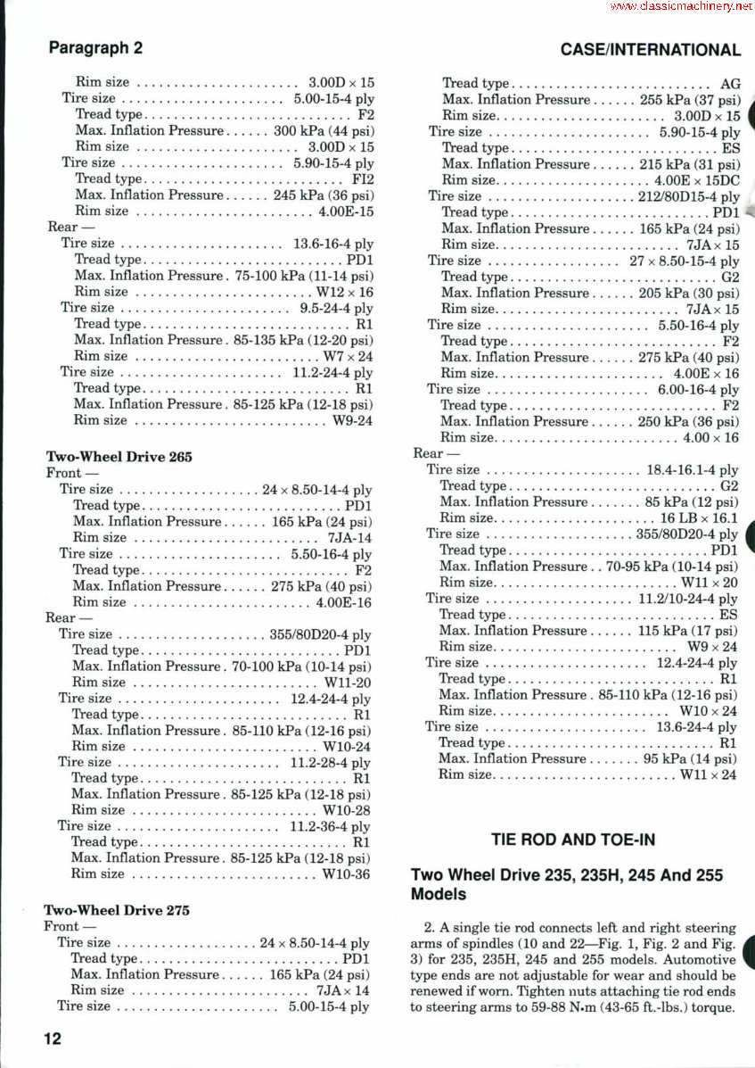
Paragraph 2 CASE/INTERNATIONAL Rim size 3.00D x 15 Tire size 5.00-15-4 ply Tread type F2 Max. Inflation Pressure 300 kPa (44 psi) Rim size 3.00D x 15 Tire size 5.90-15-4 ply Tread type FI2 Max. Inflation Pressure 245 kPa (36 psi) Rim size 4.00E-15 Rear — Tire size 13.6-16-4 ply Tread type PDl Max. Inflation Pressure. 75-100 kPa (11-14 psi) Rim size W12 x 16 Tire size 9.5-24-4 ply Tread type Rl Max. Inflation Pressure. 85-135 kPa (12-20 psi) Rim size W7 x 24 Tire size 11.2-24-4 ply Tread type Rl Max. Inflation Pressure. 85-125 kPa (12-18 psi) Rim size W9-24 Two-Wheel Drive 265 Front — Tire size 24 x 8.50-14-4 ply Tread type PDl Max. Inflation Pressure 165 kPa (24 psi) Rim size 7JA-14 Tire size 5.50-16-4 ply Tread type F2 Max. Inflation Pressure 275 kPa (40 psi) Rim size 4.00E-16 Rear — Tire size 355/80D20-4 ply Tread type PDl Max. Inflation Pressure. 70-100 kPa (10-14 psi) Rim size Wll-20 Tire size . 12.4-24-4 ply Tread type Rl Max. Inflation Pressure. 85-110 kPa (12-16 psi) Rim size WlO-24 Tire size 11.2-28-4 ply Tread type Rl Max. Inflation Pressure. 85-125 kPa (12-18 psi) Rim size WlO-28 Tire size 11.2-36-4 ply Tread type Rl Max. Inflation Pressure. 85-125 kPa (12-18 psi) Rim size WlO-36 Two-Wheel Drive 275 Front — Tire size . 24 x 8.50-14-4 ply Tread type PDl Max. Inflation Pressure 165 kPa (24 psi) Rim size 7JA x 14 Tire size 5.00-15-4 ply Tread type AG Max. Inflation Pressure 255 kPa (37 psi) i Rim size 3.00D x 15 I Tire size 5.90-15-4 ply ^ Tread type ES Max. Inflation Pressure 215 kPa (31 psi) Rim size 4.00E x 15DC j Tire size 212/80D15-4 ply Tread type PDl ^ Max. Inflation Pressure 165 kPa (24 psi) Rim size 7JA x 15 Tire size 27 x 8.50-15-4 ply Tread type G2 Max. Inflation Pressure 205 kPa (30 psi) Rim size 7JA x 15 Tire size 5.50-16-4 ply Tread type F2 Max. Inflation Pressure 275 kPa (40 psi) Rim size 4.00E x 16 Tire size 6.00-16-4 ply Tread type F2 Max. Inflation Pressure 250 kPa (36 psi) Rim size 4.00 x 16 Rear — Tire size 18.4-16.1-4 ply Tread type G2 Max. Inflation Pressure 85 kPa (12 psi) Rim size 16 LB x 16.1 Tire size 355/80D20-4 ply Tread type PDl Max. Inflation Pressure . . 70-95 kPa (10-14 psi) Rim size Wll x 20 Tire size 11.2/10-24-4 ply Tread type ES Max. Inflation Pressure ...... 115 kPa (17 psi) Rim size W9 x 24 Tire size 12.4-24-4 ply Tread type Rl Max. Inflation Pressure . 85-110 kPa (12-16 psi) Rim size WIO x 24 Tire size 13.6-24-4 ply Tread type Rl Max. Inflation Pressure 95 kPa (14 psi) Rim size Wll x 24 TIE ROD AND TOE-IN Two Wheel Drive 235, 235H, 245 And 255 Models 2. A single tie rod connects left and right steering arms of spindles (10 and 22—Fig. 1, Fig. 2 and Fig. 3) for 235, 235H, 245 and 255 models. Automotive type ends are not adjustable for wear and should be renewed if worn. Tighten nuts attaching tie rod ends to steering arms to 59-88 N.m (43-65 ft.-lbs.) torque. 12
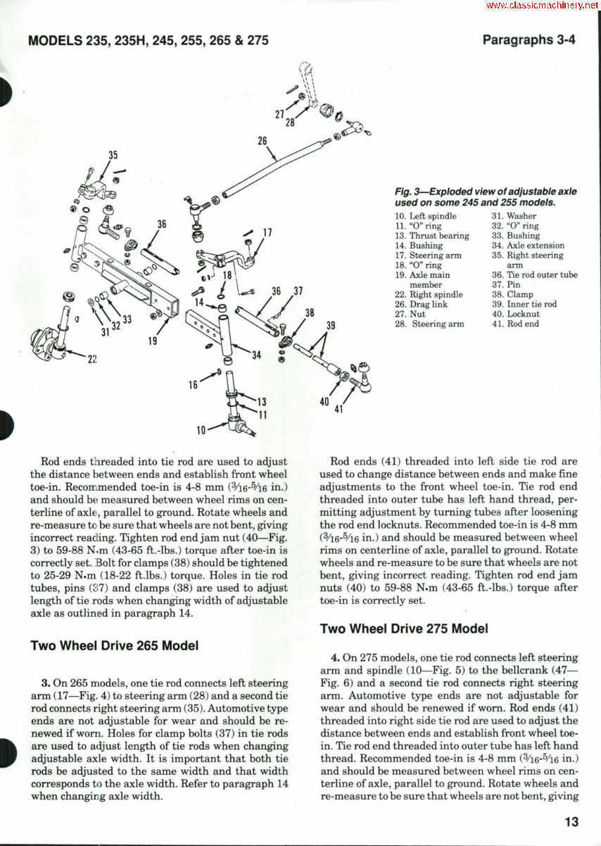
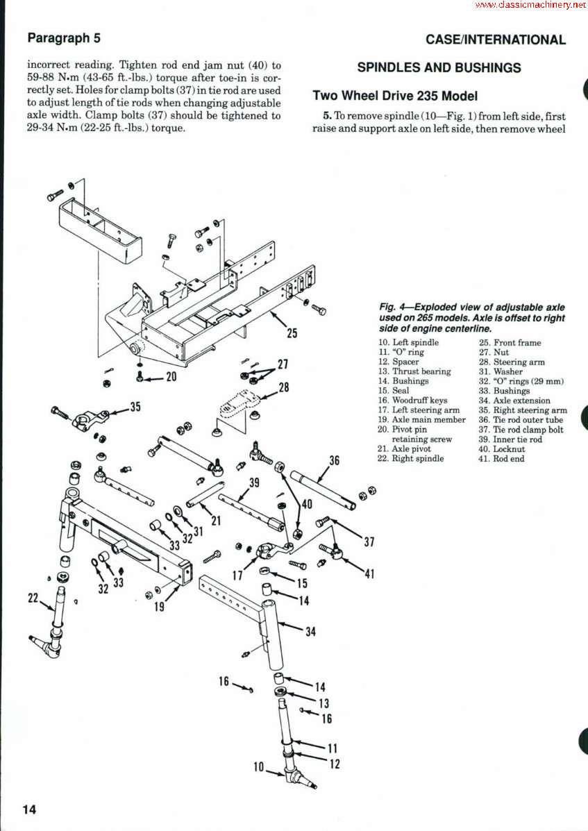
MODELS 235, 235H, 245, 255, 265 & 275 Paragraphs 3-4 Fig. 3—Exploded view of adjustable axle used on some 245 and 255 models. 10. Left spindle 11. "O" ring 13. Thrust bearing 14. Bushing 17. Steering arm 18. "O" ring 19. Axle main naember 22. Right spindle 26. Drag link 27. Nut 28. Steering arm 31- Washer 32. "O" ring 33. Bushing 34. Axle extension 35. Right steering arm 36. Tie rod outer tube 37. Pin 38. Clamp 39. Inner tie rod 40. Locknut 41. Rod end 10- Rod ends tlireaded into tie rod are used to adjust the distance between ends and establish front wheel toe-in. Recon:Lmended toe-in is 4-8 mm (^/i6-^/l6 in.) and should he measured between wheel rims on cen- terline of axle, parallel to ground. Rotate wheels and re-measure tc be sure that wheels are not bent, giving incorrect reading. Tighten rod end jam nut (40—Fig. 3) to 59-88 N.m (43-65 ft.-lbs.) torque after toe-in is correctly set. Bolt for clamps (38) should be tightened to 25-29 N.m (18-22 ft.lbs.) torque. Holes in tie rod tubes, pins (37) and clamps (38) are used to adjust length of tie rods when changing width of adjustable axle as outlined in paragraph 14. Two Wheel Drive 265 Model 3. On 265 models, one tie rod connects left steering arm (17—Fig. 4) to steering arm (28) and a second tie rod connects right steering arm (35). Automotive type ends are not adjustable for wear and should be re- newed if worn. Holes for clamp bolts (37) in tie rods are used to adjust length of tie rods when changing adjustable axle width. It is important that both tie rods be adjusted to the same width and that width corresponds to the axle width. Refer to paragraph 14 when changing axle width. Rod ends (41) threaded into left side tie rod are used to change distance between ends and make fine adjustments to the front wheel toe-in. Tie rod end threaded into outer tube has left hand thread, per- mitting adjustment by turning tubes after loosening the rod end locknuts. Recommended toe-in is 4-8 mm (3/16-5/^6 in.) and should be measured between wheel rims on centerline of axle, parallel to ground. Rotate wheels and re-measure to be sure that wheels are not bent, giving incorrect reading. Tighten rod end jam nuts (40) to 59-88 N.m (43-65 ft.-lbs.) torque after toe-in is correctly set. Two Wheel Drive 275 Model 4. On 275 models, one tie rod connects left steering arm and spindle (10—Fig. 5) to the bellcrank (47— Fig. 6) and a second tie rod connects right steering arm. Automotive type ends are not adjustable for wear and should be renewed if worn. Rod ends (41) threaded into right side tie rod are used to adjust the distance between ends and establish front wheel toe- in. Tie rod end threaded into outer tube has left hand thread. Recommended toe-in is 4-8 mm (Vi6-^/i6 in.) and should be measured between wheel rims on cen- terline of axle, parallel to ground. Rotate wheels and re-measure to be sure that wheels are not bent, giving 13
Paragraph 5 incorrect reading. Tighten rod end jam nut (40) to 59-88 N.m (43-65 fl.-lbs.) torque after toe-in is cor- rectly set. Holes for clamp bolts (37) in tie rod are used to adjust length of tie rods when changing adjustable axle width. Clamp bolts (37) should be tightened to 29-34 N.m (22-25 ft.-lbs.) torque. CASE/INTERNATIONAL SPINDLES AND BUSHINGS Two Wheel Drive 235 Model 5. To remove spindle (10—Fig. 1) from left side, first raise and support axle on left side, then remove wheel i Fig. 4—Exploded view of adjustable axle used on 265 models. Axle Is offset to right side of engine centeriine. 10. Left spindle 11. "O" ring 12. Spacer 13. Thrust bearing 14. Bushings 15. Seal 16. WoodrufFkeys 17. Left steering arm 19, Axle main member 20. Pivot pin retaining screw 21. Axle pivot 22, Right spindle 25. Front frame 27. Nut 28. Steering arm 31. Washer 32. "O" rings (29 mm) 33. Bushings 34. Axle extension 35. Right steering arm 36. Tie rod outer tube 37. Tie rod clamp bolt 39. Inner tie rod 40. Locknut 41. Rod end i 14
The Case IH 235 Tractor Full Service Repair Manual is a comprehensive guide containing all the necessary information for repairing, maintaining, rebuilding, refurbishing, or restoring the Case IH 235 Tractor. It covers diagnostic and repair procedures in great detail, providing valuable insights for both professional technicians and do-it-yourself mechanics.
This manual is a series of practical repair and service manuals used by mechanics worldwide. It includes repair procedures, service schedules, maintenance, wiring diagrams, and diagnostics. The detailed sub-steps, notes, cautions, and warnings throughout each chapter provide critical information, while the numbered instructions and bold figure numbers guide users through every repair procedure. The manual also features detailed illustrations, drawings, and photos to facilitate easy understanding of each procedure.
The Full Service Repair Manual for the Case IH 235 Tractor is available in .PDF format and .OVA file format. It is compatible with all versions of Windows and Mac operating systems. The manual is fully printable and can be saved to a hard drive or burned to a CD-ROM. Instant access eliminates the need for shipping and waiting for delivery.
The manual covers a wide range of topics including general information, specifications, engine removal, wiring diagrams, lubrication points, oil types, periodic maintenance, tune-up procedures, disassembly, reassembly, fuel and lubrication systems, electrical system, ignition, chassis, charging, starter, battery, switches, wheels, brakes, steering, suspension, axles, servicing information, service data, wire/cable/hose routing, tools, tightening torques, complete engine service, fuel system service, gearbox, exhaust system, fault finding, clutch removal and installation, transmission, bodywork, cooling system, factory maintenance schedules, electrics, brake servicing procedures, U-joint service procedures, CV joint service procedures, timing chain service, and much more.
With its extensive coverage and detailed instructions, the Case IH 235 Tractor Full Service Repair Manual is an invaluable resource for anyone involved in the repair and maintenance of the Case IH 235 Tractor.