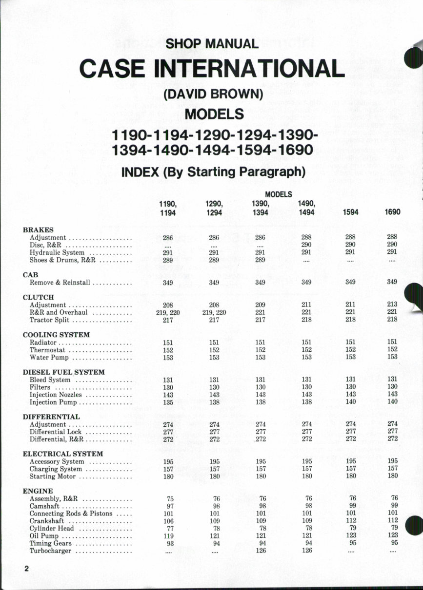
INDEX CONT. 1190, 1194 1290, 1294 MODELS 1390, 1394 1490, 1494 1594 1690 FINAL DRIVE Assembly, R&R 2*79 Overhaul 280 FRONT AXLE (Two-Wheel Drive) Axle Main Member 4 Front Support 5 Spindles 2 Tie Rod & Toe-in 3 Wheel Bearings 1 FRONT DRIVE AXLE Carraro Axle David Brown Axle HYDRAULIC SYSTEM Adjustments 312 Filters & Fluid 306 Operating Principles 303 Pump 322 Rockshai't & Linkage 341 Troubleshooting 309 Valves 326 MANUAL STEERING Assembly, R&R 50 Overhaul 51 POWER STEERING Bleeding System 57 Operating Pressure 60 Pump 61 Steering Cylinder 66 Steering Valve 63 POWER TAKE-OFF Assembly, R&R 296 Overhaul 298 TRANSM][SSION (Power Shift) Assembly, R&R Overhaul Pump Range Gearbox Valves TRANSMISSION (Synchromesh) Assembly, R&R 223 Overhaul 227 Shift Levers 222 279 280 8 1 312 306 303 322 341 309 326 279 280 4 6 2 3 1 24 312 307 304 323 341 309 326 279 282 24 7 312 307 304 323 341 309 326 279 284 4 6 2 3 1 24 279 284 4 6 2 a 1 24 319 307 304 323 342 309 326 312 307 304 323 342 309 326 57 60 62 66 63 296 298 .... 223 227 222 57 60 62 66 63 296 300 258 260 257 268 254 225 237, 246 222 58 60 62 68 63 296 300 258 260 257 268 254 225 237, 246 222 58 60 62 68 63 296 302 258 260 257 268 254 225 246 222 58 60 62 68 63 296 302 258 260 257 268 254 22S 246 222 DUAL DIMENSIONS This sendee manual provides specifications in both metric (SI) and U.S. customary systems of measurement. The first specification is given in the measuring system perceived b^ us to be the preferred system when servicing a particular component, while the second specification (given in parenthesis) is the converted measurement. For instance, a specification of "0.28 mm (0.011 inch)" would indicate that we feel the preferred measurement in this instance is the metric (SI) system of measuremtsnt and the IJ.S. customary equivalent of 0.28 mm is 0.011 inch.
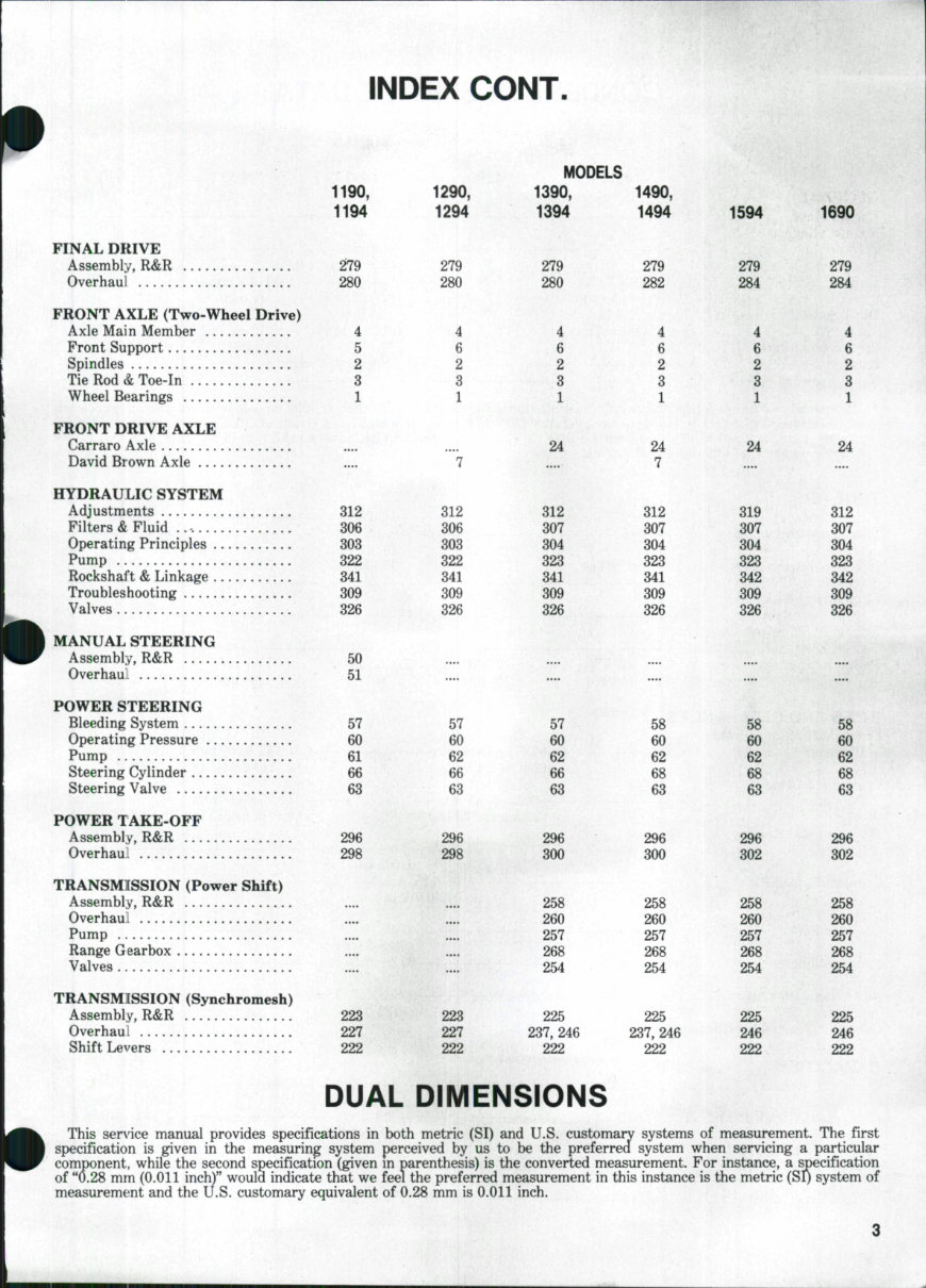
CONDENSED SERVICE DATA MODELS 1190 1290 1390 1490 1690 GENERAL Engine Make Own No. of Cylinders 3 4 4 4 6 Bore 100 mm (3.939 in.) Stroke 114.3 mm * 114.3 mm (4.5 in.) (4.5 in.) Displacement 2.7 liter * 3.6 liter 3.6 liter 5.4 liter (164 cu. in.) (219 cu. in.) (219 cu. in.) (329 cu. in.) Compression Ratio 17:1 17:1 17:1 16:1 16:1 Battery 12-Volt, Negative Ground No. of Forward Speeds 12 * 1290 models with independent pto clutch manufactured before P.I.N. 11052369, or 1290 models with continuous pto clutch manufactured before P.I.N. 11052410 use a 3.2 liter (195 cu. in.) engine which has a stroke of 101.6 mm (4.0 inches). All 1290 models manufactured after these used 3.6 liter (219 cu. in.) engines which have a 114.3 mm (4.5 inches) stroke. Service procedures are the same for either engine. TUNE-UP Firing Order Valve Clearance (Cold) Injection Timing Engine Low Idle Rpm . Engine High Idle (No-Load) Rpm Engine Rated Speed (Full Load) Power Rating SIZES AND CLEARANCES Crankshaft Main Journal Diameter — Crankpin Journal Diameter — Main and Rod Bearing Running Clearance — Crankshaft End Play — Cylinder Bore — Piston Diameter — Valve Stem Diameter — Camshaft Journal Specifications, See Paragraph CAPACITIES Cooling System ........ Crankcase (With Filter) .... Transmission, Hydraulic and Differential Case — 1-2-3 1-5-3-6-2-4 16° BTDC 17° BTDC -0.25 mm— (0.010 in.) 17*^ BTDC 750 20° BTDC 25° BTDC -2350-2375- 2200— 37 kW (49 hp) 45 kW (60 hp) -63.474-63.487 mm- (2.4990-2.4995 in.) 52 kW (70 hp) 66 kW (88 hp) 2450 2300 82 kW (110 hp) —60.27-60.29 mm— (2.3730-2.3735 in.) - 66.65-66.66 mm 69.84-69.85 mm (2.6240-2.6245 in.) (2.749-2.750 in.) - 63.45-63.46 mm 60.27-60.28 mm (2.4980-2.4985 in.) (2.3728-2.3732 in.) -0.05-0.10 mm- (0.002-0.004 in.) —0.05-0.25 mm (0.002-0.010 in.) 0.15-0.25 mm (0.006- 0.010 in.) 97 8.5 liters (9 qts.) 6.25 liters (6.6 qts.) 98 -100.046-100.066 mm- (3.9388-3.9396 in.) —99.86-99.88 mm— (3.9315-3.9323 in.) —9.454-9.479 mm— (0.3722-0.3732 in.) 98 98 -14.2 liters- (15 qts.) -7.4 liters- (7.8 qts.) 99 15.3 liters (16 qts.) 12.5 liters (13.2 qts.) -27.5 liters- -42 liters- Fluid Type (29 U.S. qts.) (44.5 U.S. qts.) Case PTF Fluid or Hy-Tran Plus
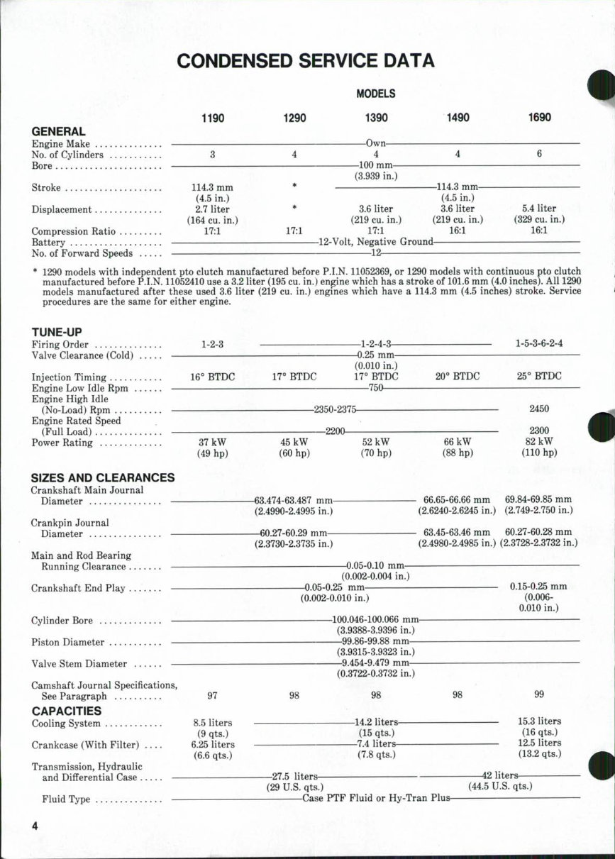
CONDENSED SERVICE DATA CONT. 1190 CAPACITIES (Cont) Final Drive (Each) Fluid Type Power Ste€Ting 0.9 liters (1 U.S. qt.) Fluid Type Manual Steering Gear 1.2 liters (1.3 U.S. qts.) Fluid Type Case FDL SAE 140 Front Drive Axle Differential- David Brown Fluid Type Carraro Fluid Type Front Drive Axle Final Drive (Each)— David Brown Fluid Type Carraro Fluid Type 1290 -2.3 liters- MODELS 1390 (2.5 U.S. qts.) -Case ET HB Fiuid- 1.25 liters— (1.5 U.S. qts.) TCH Fluid 1490 6.8 liters (7 U.S. qts.) 1690 7.5 liters (8 U.S. qts.) -8 liters- (8.5 U.S. qts.) -Case FDL SAE 90- -0.9 liters^ (1 U.S. qt.) -Case FDL SAE 90- -4 liters- (4.25 U.S. qts.) -Case FDL SAE 90- -1.4 liters- (1.5 U.S. qts.) -Case FDL SAE 90- 17:1 1194 1294 GENERAL Engine Make No. of Cylinders 3 4 Bore Stroke Displacement 2.7 liter (164 cu. in.) Compression Ratio 17:1 Battery No. of Forv/ard Speeds TUNE-UP Firing Order : . 1-2-3 Valve Clearance (Cold) Injection Timing 16° BTDC 17° BTDC Engine Lov/ Idle Rpm 750 Engine High Idle (No-Load) Rpm Engine Full Load Rpm Power Rating 35 kW 45 kW (49 hp) (62 hp) MODELS 1394 Own 4 —100 mm— (3.939 in.) —114.3 mm— (4.5 in.) —3.6 liter— (219 cu. in.) 1494 1594 5.4 liter (329 cu. in.) -12 volts, Negative Ground- 12 —1-2-4-3 1-5-3-6-2-4 -0.25 mm (0.010 in.) IT BTDC 20^ BTDC 25° BTDC 600-650 -2350-2375- -2200- 53 kW (77 hp) 61 kW (85 hp) 2450 2300 72 kW (97 hp)
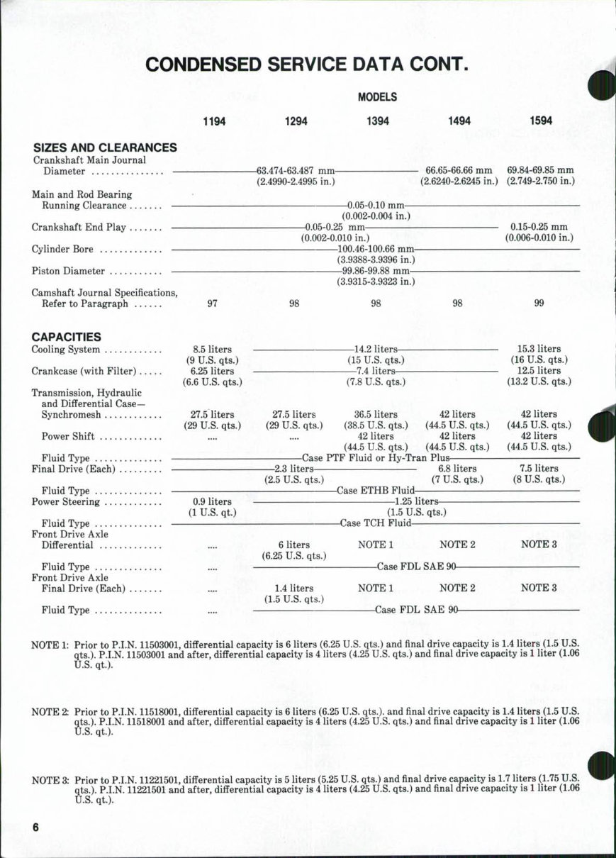
CONDENSED SERVICE DATA CONT. 1194 1294 MODELS 1394 1494 1594 SIZES AND CLEARANCES Crankshaft Main Journal Diameter Main and Rod Bearing Running Clearance Crankshaft End Play Cylinder Bore Piston Diameter Camshaft Journal Specifications, Refer to Paragraph 97 CAPACITIES Cooling System 8.5 liters (9 U.S. qts.) Crankcase (with Filter) 6.25 liters (6.6 U.S. qts.) Transmission, Hydraulic and Differential Case— Synchromesh 27.5 liters (29 U.S. qts.) Power Shift Fluid Type Final Drive (Each) Fluid Type Power Steering 0.9 liters (1 U.S. qt.) Fluid Type Front Drive Axle Differential .... : Fluid Type Front Drive Axle Final Drive (Each) Fluid Type -63.474-63.487 mm- (2.4990-2.4995 in.) - 66.65-66.66 mm (2.6240-2.6245 in.) 69.84-69.85 mm (2.749-2.750 in.) -0.05-0.10 mm- (0.002-0.004 in.) -0.05-0.25 mm (0.002-0.010 in.) 100.46-100.66 mm- (3.9388-3.9396 in.) 99.86-99.88 mm— (3.9315-3.9323 in.) 0.15-0.25 mm (0.006-0.010 in.) 98 98 —14.2 liters— (15 U.S. qts.) —7.4 liters— (7.8 U.S. qts.) 98 15.3 liters (16 U.S. qts.) 12.5 liters (13.2 U.S. qts.) 27.5 liters 36.5 liters 42 liters 42 liters (29 U.S. qts.) (38.5 U.S. qts.) (44.5 U.S. qts.) (44.5 U.S. qts.) 42 liters 42 liters 42 liters (44.5 U.S. qts.) (44.5 U.S. qts.) (44.5 U.S. qts.) Case PTF Fluid or Hy-Tran Plus- -2.3 liters- (2.5 U.S. qts.) -Case ETHB Fluid- 6.8 liters (7 U.S. qts.) 7.5 liters (8 U.S. qts.) 1.25 liters— (1.5 U.S. qts.) -Case TCH Fluid 6 liters (6.25 U.S. qts.) NOTE 1 NOTE 2 Case FDL SAE 90 NOTE 3 1.4 liters (1.5 U.S. qts.) NOTE 1 NOTE 2 NOTE 3 Case FDL SAE 90 NOTE 1: Prior to P.I.N. 11503001, diflFerential capacity is 6 liters (6.25 U.S. qts.) and final drive capacity is 1.4 liters (1.5 U.S. qts.). P.I.N. 11503001 and after, differential capacity is 4 liters (4.25 U.S. qts.) and final drive capacity is 1 liter (1.06 U.S. qt). NOTE 2: Prior to P.I.N. 11518001, differential capacity is 6 liters (6.25 U.S. qts.). and final drive capacity is 1.4 liters (1.5 U.S. 3ts.). P.I.N. 11518001 and after, differential capacity is 4 liters (4.25 U.S. qts.) and final drive capacity is 1 liter (1.06 •J.S. qt.). qts U.I NOTE 3: Prior to P.I.N. 11221501, differential capacity is 5 liters (5.25 U.S. qts.) and final drive capacity is 1.7 liters (1.75 U.S. :s.). P.I.N. 11221501 and after, differential capacity is 4 liters (4.25 U.S. qts.) and final drive capacity is 1 liter (1.06 qts.. U.S. qt).
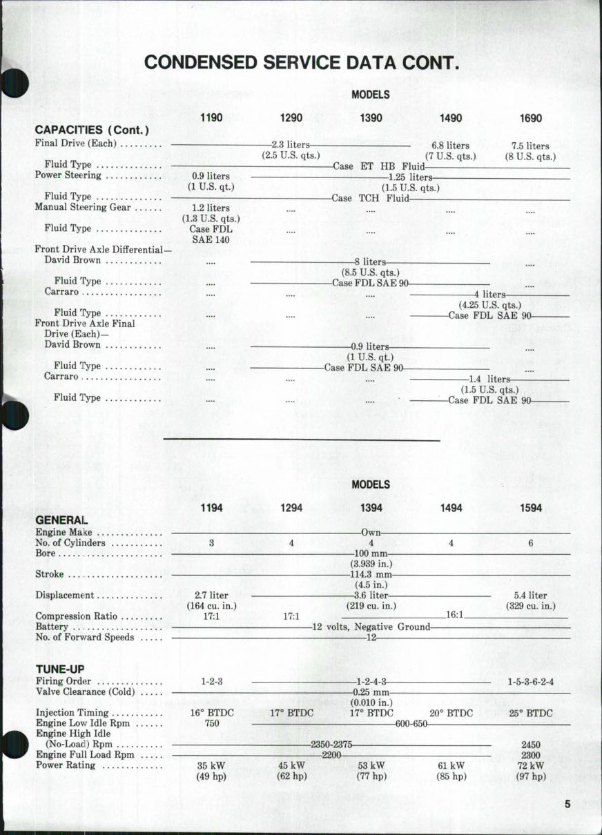
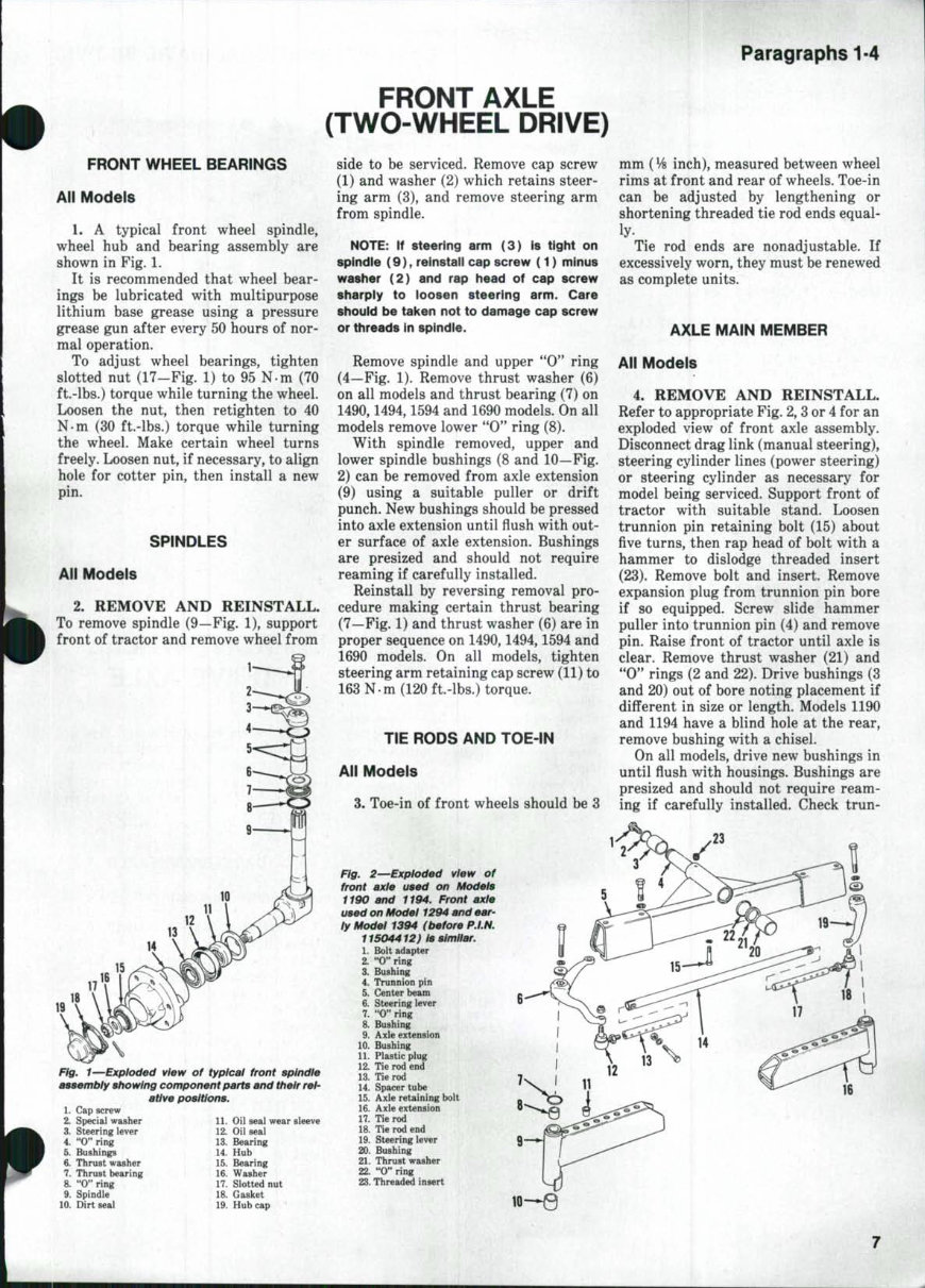
Paragraphs 1-4 FRONT WHEEL BEARINGS All Models 1. A typical front wheel spindle, wheel hub and bearing assembly are shown in Fig. 1. It is recommended that wheel bear- ings be lubricated with multipurpose lithium base grease using a pressure grease gun after every 50 hours of nor- mal operation. To adjust wheel bearings, tighten slotted nut (17—Fig. 1) to 95 N-m (70 ft.-lbs.) torque while turning the wheel. Loosen the nut, then retighten to 40 N-m (30 ft.-lbs.) torque while turning the wheel. Make certain wheel turns freely. Loosen nut, if necessary, to align hole for cotter pin, then install a new pin. SPINDLES All Models 2. REMOVE AND REINSTALL. To remove spindle (9—Fig. 1), support front of tractor and remove wheel from FRONT AXLE (TWO-WHEEL DRIVE) side to be serviced. Remove cap screw (1) and washer (2) which retains steer- ing arm (3), and remove steering arm from spindle. . • NOTE: If steering arm (3) is tight on spindie ( 9 ) , reinstall cap screw ( 1 ) minus washer (2) and rap head of cap screw sharply to loosen steering arm. Care should be taken not to damage cap screw or threads in spindie. Remove spindle and upper "0'^ ring (4—Fig. 1). Remove thrust washer (6) on all models and thrust bearing (7) on 1490,1494,1594 and 1690 models. On all models remove lower "0" ring (8). With spindle removed, upper and lower spindle bushings (8 and 10—Fig. 2) can be removed from axle extension (9) using a suitable puller or drift punch. New bushings should be pressed into axle extension until flush with out- er surface of axle extension. Bushings are presized and should not require reaming if carefully installed. Reinstall by reversing removal pro- cedure making certain thrust bearing (7—Fig. 1) and thrust washer (6) are in proper sequence on 1490,1494,1594 and 1690 models. On all models, tighten steering arm retaining cap screw (11) to 163 N-m (120 ft.-lbs.) torque. Fig. 1—Exploded view of typical front spindle assembly showing component parts and their rel- ative positions. 1. Cap screw 2. Special washer 3. Steering lever 4. "0" ring 5. Bushings 6. Thrust washer 7. Thrust bearing 8. "0" ring 9. Spindle 10. Dirt seal 11. Oil seat wear sleeve 12. Oil seal 13. Bearing ^ 14. Hub 15. Bearing ' 16. Washer 17. Slotted nut 18. Gasket 19. Hubcap mm ( VB inch), measured between wheel rims at front and rear of wheels. Toe-in can be adjusted by lengthening or shortening threaded tie rod ends equal- ly. Tie rod ends are nonadjustable. If excessively worn, they must be renewed as complete units. AXLE MAIN MEMBER TIE RODS AND TOE-IN Alt Models 3, Toe-in of front wheels should be 3 All Models 4. REMOVE AND REINSTALL. Refer to appropriate Fig. 2, 3 or 4 for an exploded view of front axle assembly. Disconnect drag link (manual steering), steering cylinder lines (power steering) or steering cylinder as necessary for model being serviced. Support front of tractor with suitable stand. Loosen trunnion pin retaining bolt (15) about five turns, then rap head of bolt with a hammer to dislodge threaded insert (23). Remove bolt and insert. Remove expansion plug from trunnion pin bore if so equipped. Screw slide hammer puller into trunnion pin (4) and remove pin. Raise front of tractor until axle is clear. Remove thrust washer (21) and "0" rings (2 and 22). Drive bushings (3 and 20) out of bore noting placement if different in size or length. Models 1190 and 1194 have a blind hole at the rear, remove bushing with a chisel. On all models, drive new bushings in until flush with housings. Bushings are presized and should not require ream- ing if carefully installed. Check trun- Flg. 2—Exploded view of front axle used on Models i190 and if94. Front axle used on Model 1294 and ear- ly Model 1394 (before P.I.N. 11504412) is similar. 1. Bolt adapter 2. "0" ring 3. Bushing 4. Trunnion pin 5. Center beam 6. Steering lever 7. "0" ring 8. Bushing 9. Axle extension 10. Bushing U. Plastic plug 12. Tie rod end 13. Tie rod 14. Spacer tube 15. Axle retaining bolt 16. Axle extension 17. Tie rod 18. Tie rod end 19. Steering lever 20. Bushing 21. Thrust washer 22. "O" ring 23. Threaded insert
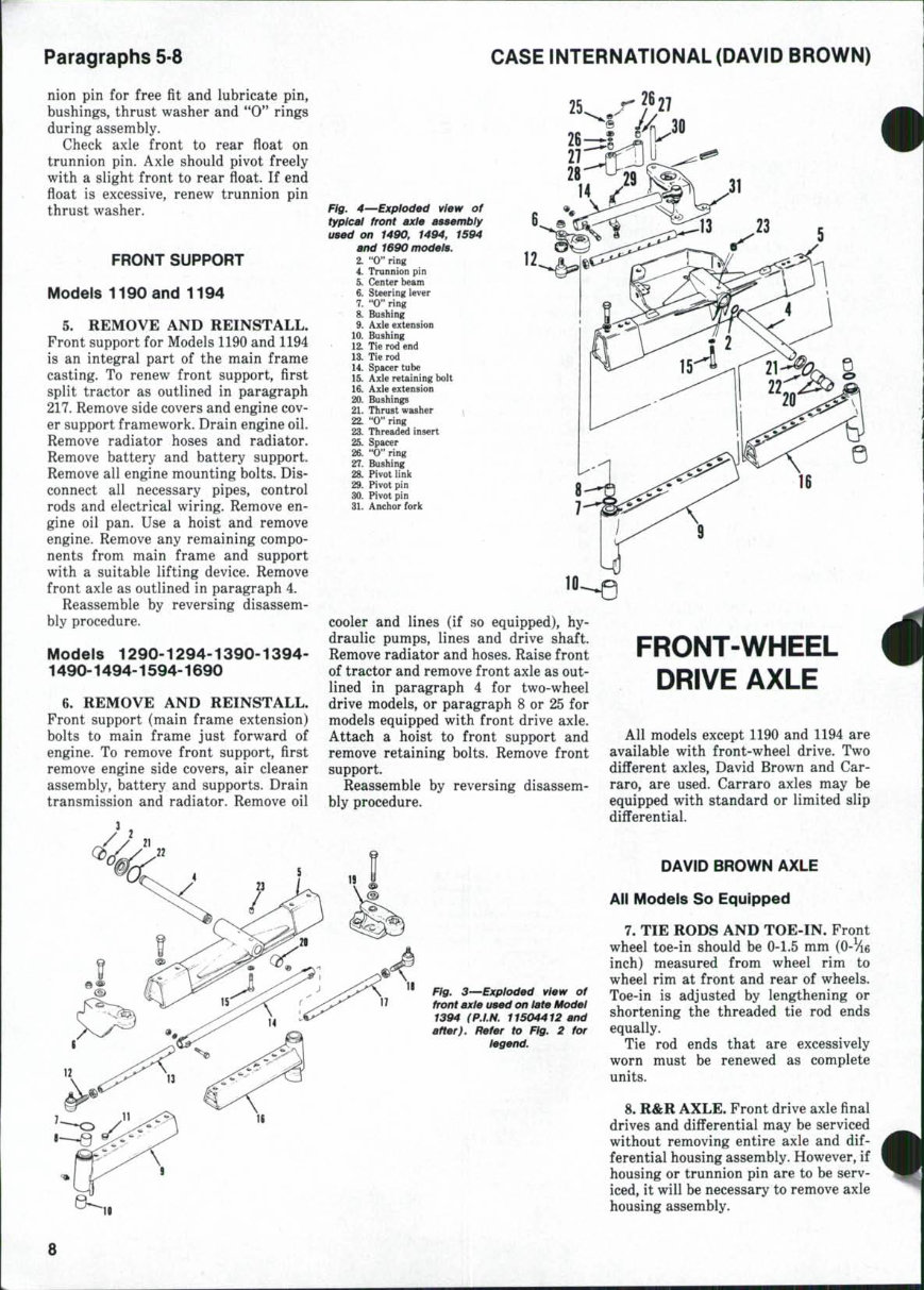
Paragraphs 5-8 CASE INTERNATIONAL (DAVID BROWN) nion pin for free fit and lubricate pin, bushings, thrust washer and "0" rings during assembly. Check axle front to rear fioat on trunnion pin. Axle should pivot freely with a slight front to rear float. If end float is excessive, renew trunnion pin thrust washer. • . FRONT SUPPORT Models 1190 and 1194 5. REMOVE AND REINSTALL. Front support for Models 1190 and 1194 is an integral part of the main frame casting. To renew front support, first split tractor as outlined in paragraph 217. Remove side covers and engine cov- er support framework. Drain engine oil. Remove radiator hoses and radiator. Remove battery and battery support. Remove all engine mounting bolts. Dis- connect all necessary pipes, control rods and electrical wiring. Remove en- gine oil pan. Use a hoist and remove engine. Remove any remaining compo- nents from main frame and support with a suitable lifting device. Remove front axle as outlined in paragraph 4. Reassemble by reversing disassem- bly procedure. Models 1290-1294-1390-1394- 1490-1494-1594-1690 6. REMOVE AND REINSTALL. Front support (main frame extension) bolts to main frame just forward of engine. To remove front support, first remove engine side covers, air cleaner assembly, battery and supports. Drain transmission and radiator. Remove oil 25 Fig. 4—Exploded view of typical front axle aBsembly used on 1490, 1494, 1594 and 1690 models. 2. "0" ring 4. Trunnion pin 5. Center beam ' 6. Steering lever 7. "0" ring 8. Bushing 9. Axle extension 10. Bushing 12. Tie rod end 13. Tie rod 14. Spacer tube 15. Axle retaining bolt 16. Axle extension 20. Bushings 21. Thrust washer i 22. "0" ring 23. Threaded insert 25. Spacer 26. "0" ring 27. Bushing 2&. Pivot link 29. Pivot pin 30. Pivot pin 31. Anchor fork cooler and lines (if so equipped), hy- draulic pumps, lines and drive shaft. Remove radiator and hoses. Raise front of tractor and remove front axle as out- lined in paragraph 4 for two-wheel drive models, or paragraph 8 or 25 for models equipped with front drive axle. Attach a hoist to front support and remove retaining bolts. Remove front support. Reassemble by reversing disassem- bly procedure. Fig. 3—Exploded view of front axle used on late Model 1394 (P.I.N. 11504412 and after), Refer to Fig. 2 for legend. FRONT-WHEEL DRIVE AXLE 4 All models except 1190 and 1194 are available with front-wheel drive. Two different axles, David Brown and Car- raro, are used. Carraro axles may be equipped with standard or limited slip differential. DAVID BROWN AXLE All Models So Equipped 7. TIE RODS AND TOE-IN. Front wheel toe-in should be 0-1.5 mm (0-We inch) measured from wheel rim to wheel rim at front and rear of wheels. Toe-in is adjusted by lengthening or shortening the threaded tie rod ends equally. Tie rod ends that are excessively worn must be renewed as complete units. 8. R&R AXLE. Front drive axle final drives and differential may be serviced without removing entire axle and dif- ferential housing assembly. However, if housing or trunnion pin are to be serv- iced, it will be necessary to remove axle housing assembly.
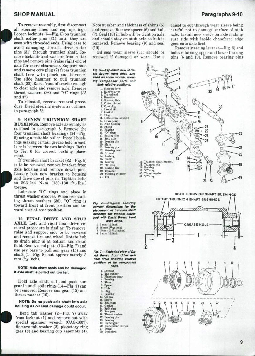
SHOP MANUAL Paragraphs 9-10 To remove assembly, first disconnect all steering lines and cap openings. Loosen locknuts (6—Fig. 5) on trunnion shaft cotter pins (31) until they are even with threaded ends. Using care to avoid damaging threads, drive cotter pins (31) through trunnion shaft. Re- move locknuts and washers from cotter pins and remove pins (raise right end of axle for more clearance). Support axle and remove core plug (7) from trunnion shaft bore with punch and hammer. Use slide hammer to pull trunnion shaft (33). Raise front of tractor enough to clear axle and remove axle. Remove thrust washers (36) and "0" rings (35 and 37). To reinstall, reverse removal proce- dure. Bleed steering system as outlined in paragraph 58. 9. RENEW TRUNNION SHAFT BUSHINGS. Remove axle assembly as outlined in paragraph 8. Remove the four trunnion shaft bushings (34—Fig. 5) using a suitable puller. Install bush- ings making certain grease hole in each bore is between the two bushings. Refer to Fig. 6 for correct bushing place- ment. If trunnion shaft bracket (32—Fig. 5) is to be renewed, remove bracket from axle housing and remove dowel pins. Loosely bolt new bracket to housing and drive dowel pins in. Tighten bolts to 203-244 N-m (150-180 ft.-lbs.) torque. Lubricate "0** rings and place in thrust washer grooves. When reinstall- ing thrust washers (36), "0" ring is toward front at front position and to- ward rear at rear position. 10. FINAL DRIVE AND STUB AXLE. Left and right final drive re- moval procedure is similar. To remove, raise and support side to be serviced and remove tire and wheel. Rotate hub so drain plug is at bottom and drain fluid. Remove end plate (12—Fig. 7) and use pry bars to pull sun gear (15) and shaft (1—Fig. 8) out approximately 5 mm {%B inch). NOTE: Axle shaft seals can be damaged If axle shaft is pulled out too far. Hold axle shaft out and push sun gear in until split rings (14—Fig. 7) can be removed. Remove sun gear (15) and thrust washer (16). NOTE: Do no push axle shaft into axle housing as oil seal damage could occur. Bend tab washer (2—Fig. 7) away from locknut (1) and remove nut with special spanner wrench (CAS-1607). Remove tab washer (2), planetary ring gear (3) and bearing cup assembly (4). Note number and thickness of shims (5) and remove. Remove spacer (6) and hub (7). Seal (10) in hub will be tight on axle and should stay on stub axle as hub is removed. Remove bearing (9) and seal (10). Oil seal wear sleeve (11) should be renewed if damaged or worn. Use a Fig. 5—Expioded view of Da- vid Brown front drive axie used on some models show- ing component parts and their relative positions. 1. Steering lever 2. Rubber cover 3. Tie rod end 4. Breather 5. Steering link 6. Cotter pin nut 7. Core plug 8. Dowel pin 9. Gasket 10. Plug 11. Differential housing 12. Drain plug 13. Axle housing 14. Shield 15. Bearing 16. "0" rings 17. Sealing disc 18. Stub axle 19. Bearing pin 20. Shim 21. Bearing pin 22. Steering lever 23. Oil seal 24. Bushing 25. Shield 26 Bearing 27. "O" ring 28. Sealing disc 29. Breather 30. Steering cylinder 31. Pin chisel to cut through wear sleeve being careful not to damage surface of stub axle. Install new sleeve on axle making sure side with inside chamfered edge goes onto axle first. Remove steering lever (4—Fig. 8) and bolts retaining upper and lower bearing pins (6 and 10). Remove bearing pins 2&. Trunnion shaft bracket 33. Trunnion pin 34. Bushing 35. "O"ring 36. Thrust washer 37. "0" ring 17 24 23 Fig. 6—Diagram showing correct dimensions for the placement of trunnion shaft bushings for models equip- ped with David Brown front drive axies. 1. 3 mm (l/g inch) 2. 15 mm (19/32 inch) 3. 55 mm {2 Vie inches) 4. 3 mm (Vg inch) Fig. 7^Exploded view of Da- vid Brown front drive axie finai drive showing reiative position of its component parts. 1. Locknut 2. Tab washer 3. Planetary gear 4. Bearing 5. Shim 6. Spacer 7. Hub 8. Plug 9. Bearing 10. Oil seal 11. Sleeve 12. End plate 13. Gasket 14. Split ring 15. Sun gear 16. Thrust washer 17. Bearing pin 18. Bearing 19. Planet gear 20. Planet gear carrier 21. Dowel 22. Lockplate REAR TRUNNION SHAFT BUSHINGS FRONT TRUNNION SHAFT BUSHINGS 1 2 3 4 5 6 7 8 10 11 12 13 14 15 16 17 18 19 20 21 22
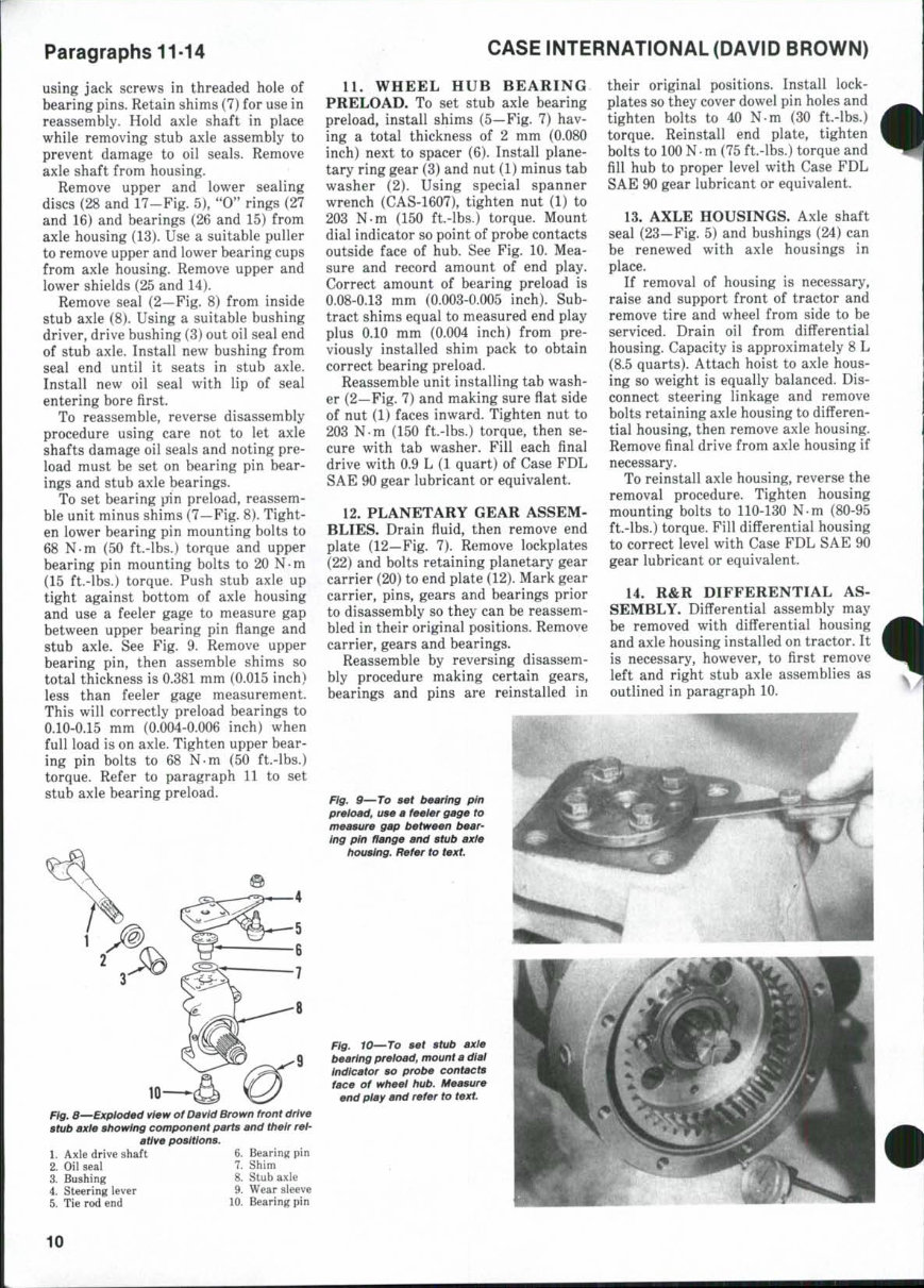
Paragraphs 11-14 using jack screws in threaded hole of bearing pins. Retain shims (7) for use in reassembly. Hold axle shaft in place while removing stub axle assembly to prevent damage to oil seals. Remove axle shaft from housing. Remove upper and lower sealing discs (28 and 17-Fig. 5), "0" rings (27 and 16) and bearings (26 and 15) from axle housing (13). Use a suitable puller to remove upper and lower bearing cups from axle housing. Remove upper and lower shields (25 and 14). Remove seal (2—Fig. 8) from inside stub axle (8). Using a suitable bushing driver, drive bushing (3) out oil seal end of stub axle. Install new bushing from seal end until it seats in stub axle. Install new oil seal with lip of seal entering bore first. To reassemble, reverse disassembly procedure using care not to let axle shafts damage oil seals and noting pre- load must be set on bearing pin bear- ings and stub axle bearings. To set bearing pfin preload, reassem- ble unit minus shims (7—Fig. 8). Tight- en lower bearing pin mounting bolts to 68 N-m (50 ft.-lbs.) torque and upper bearing pin mounting bolts to 20 N-m (15 ft.-lbs.) torque. Push stub axle up tight against bottom of axle housing and use a feeler gage to measure gap between upper bearing pin flange and stub axle. See Fig. 9. Remove upper bearing pin, then assemble shims so total thickness is 0.381 mm (0.015 inch) less than feeler gage measurement. This will correctly preload bearings to 0.10-0.15 mm (0.004-0.006 inch) when full load is on axle. Tighten upper bear- ing pin bolts to 68 N-m (50 ft.-lbs.) torque. Refer to paragraph 11 to set stub axle bearing preload. CASE INTERNATIONAL (DAVID BROWN) 10- _ _ flg^ S—Exploded view of David Brown front drive stub axle showing component parts and their rel- ative positions. 11. WHEEL HUB BEARING PRELOAD. To set stub axle bearing preload, install shims (5—Fig. 7) hav- ing a total thickness of 2 mm (0.080 inch) next to spacer (6). Install plane- tary ring gear (3) and nut (1) minus tab washer (2). Using special spanner wrench (CAS-1607), tighten nut (1) to 203 N.m (150 ft.-lbs.) torque. Mount dial indicator so point of probe contacts outside face of hub. See Fig. 10. Mea- sure and record amount of end play. Correct amount of bearing preload is 0.08-0.13 mm (0.003-0.005 inch). Sub- tract shims equal to measured end play plus 0.10 mm (0.004 inch) from pre- viously installed shim pack to obtain correct bearing preload. Reassemble unit installing tab wash- er (2—Fig. 7) and making sure flat side of nut (1) faces inward. Tighten nut to 203 N-m (150 ft.-lbs.) torque, then se- cure with tab washer. Fill each final drive with 0.9 L (1 quart) of Case FDL SAE 90 gear lubricant or equivalent. 12. PLANETARY GEAR ASSEM- BLIES. Drain fluid, then remove end plate (12—Fig. 7). Remove lockplates (22) and bolts retaining planetary gear carrier (20) to end plate (12). Mark gear carrier, pins, gears and bearings prior to disassembly so they can be reassem- bled in their original positions. Remove carrier, gears and bearings. Reassemble by reversing disassem- bly procedure making certain gears, bearings and pins are reinstalled in their original positions. Install lock- plates so they cover dowel pin holes and tighten bolts to 40 N-m (30 ft.-lbs.) torque. Reinstall end plate, tighten bolts to 100 N m (75 ft.-lbs.) torque and fill hub to proper level with Case FDL SAE 90 gear lubricant or equivalent. 13. AXLE HOUSINGS, Axle shaft seal (23—Fig. 5) and bushings (24) can be renewed with axle housings in place. If removal of housing is necessary, raise and support front of tractor and remove tire and wheel from side to be serviced. Drain oil from differential housing. Capacity is approximately 8 L (8.5 quarts). Attach hoist to axle hous- ing so weight is equally balanced. Dis- connect steering linkage and remove bolts retaining axle housing to differen- tial housing, then remove axle housing. Remove final drive from axle housing if necessary. To reinstall axle housing, reverse the removal procedure. Tighten housing mounting bolts to 110-130 N-m (80-95 ft.-lbs.) torque. Fill differential housing to correct level with Case FDL SAE 90 gear lubricant or equivalent. 14. R&R DIFFERENTIAL AS- SEMBLY. Differential assembly may be removed with differential housing and axle housing installed on tractor. It is necessary, however, to first remove left and right stub axle assemblies as outlined in paragraph 10. Fig. 9—To set bearing pin preioad, use a feeier gage to measure gap between bear- ing pin fiange and stub axie housing. Refer to text. Fig. 10—To set stub axle bearing preload, mount a dlai indicator so probe contacts face of wheel hub. Measure end play and refer to text. 1. Axle drive shaft 2. Oil seal 3. Bushing 4. Steering lever 5. Tie rod end 6. Bearing pin 7. Shim 8. Stub axle 9. Wear sleeve 10. Bearing pin 10
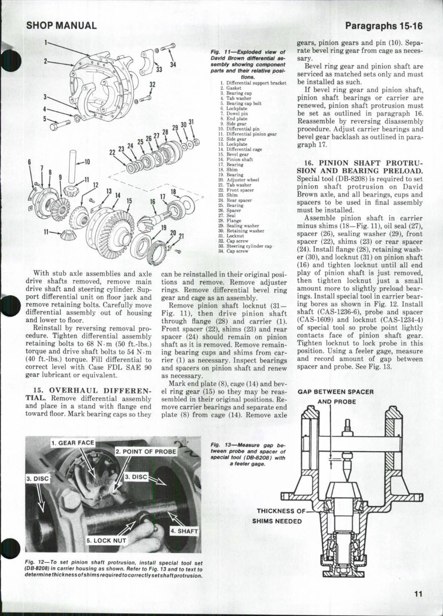
SHOP MANUAL Paragraphs 15-16 With stub axle assemblies and axle drive shafts removed, remove main drive shaft and steering cylinder. Sup- port diflferential unit on floor jack and remove retaining bolts. Carefully move differential assembly out of housing and lower to floor. Reinstall by reversing removal pro- cedure. Tighten differential assembly retaining bolts to 68 N m (50 ft.-lbs.) torque and drive shaft bolts to 54 N m (40 ft.-lbs.) torque. Fill differential to correct level with Case FDL SAE 90 gear lubricant or equivalent. 15. OVERHAUL DIFFEREN- TIAL. Remove differential assembly and place in a stand with flange end toward floor. Mark bearing caps so they Fig. 11—Exploded view of David Brown differentiai as- sembiy showing component parts and their relative posi- tions. 1. Differential support bracket 2. Gasket 3. Bearing cap 4. Tab washer 5. Bearing cap bolt 6. Lockplate 7. Dowel pin 8. End plate 9. Side gear 10. Differential pin 11. Differential pinion gear 12. Side gear 13. Lockplate 14. Differential cage 15. Bevel gear 16. Pinion shaft 17. Bearing 18. Shim 19. Bearing 20. Adjuster wheel 21. Tab washer 22. Front spacer 23. Shim 24. Rear spacer 25. Bearing 26. Spacer 27. Seal 28. Flange 29. Sealing washer 30. Retaining washer 31. Locknut 32. Cap screw 33. Steering cylinder cap 34. Cap screw can be reinstalled in their original posi- tions and remove. Remove adjuster rings. Remove differential bevel ring gear and cage as an assembly. Remove pinion shaft locknut (31 — Fig. 11), then drive pinion shaft through flange (28) and carrier (1). Front spacer (22), shims (23) and rear spacer (24) should remain on pinion shaft as it is removed. Remove remain- ing bearing cups and shims from car- rier (1) as necessary. Inspect bearings and spacers on pinion shaft and renew as necessary. Mark end plate (8), cage (14) and bev- el ring gear (15) so they may be reas- sembled in their original positions. Re- move carrier bearings and separate end plate (8) from cage (14). Remove axle Fig. 13—Measure gap be- tween probe and spacer of special tool (DB-8208) with a feeier gage. gears, pinion gears and pin (10). Sepa- rate bevel ring gear from cage as neces- sary. Bevel ring gear and pinion shaft are serviced as matched sets only and must be installed as such. If bevel ring gear and pinion shaft, pinion shaft bearings or carrier are renewed, pinion shaft protrusion must be set as outlined in paragraph 16. Reassemble by reversing disassembly procedure. Adjust carrier bearings and bevel gear backlash as outlined in para- graph 17. 16. PINION SHAFT PROTRU- SION AND BEARING PRELOAD. Special tool (DB-8208) is required to set pinion shaft protrusion on David Brown axle, and all bearings, cups and spacers to be used in final assembly must be installed. Assemble pinion shaft in carrier minus shims (18—Fig. 11), oil seal (27), spacer (26), sealing washer (29), front spacer (22), shims (23) or rear spacer (24). Install flange (28), retaining wash- er (30), and locknut (31) on pinion shaft (16) and tighten locknut until all end play of pinion shaft is just removed, then tighten locknut just a small amount more to slightly preload bear- ings. Install special tool in carrier bear- ing bores as shown in Fig. 12. Install shaft (CAS-1236-6), probe and spacer (CAS-1609) and locknut (CAS-1234-4) of special tool so probe point lightly contacts face of pinion shaft gear. Tighten locknut to lock probe in this position. Using a feeler gage, measure and record amount of gap between spacer and probe. See Fig. 13. GAP BETWEEN SPACER AND PROBE THICKNESS OF SHIMS HEEDED Fig. 12—To set pinion shaft protrusion, install special tool set iDB'8208) in carrier housing as shown. Refer to Fig. 13 and to text to determlnethicknessofshimsrequiredtocorrectlysetshaftprotrusion. 11
This professional technical manual contains service, maintenance, and troubleshooting information for your Case IH 1490, covering all models, engines, trim, and transmission types. It is useful for both professional mechanics and DIY enthusiasts.
The manual includes detailed information on the following:
Case IH 1490 Engine
Case IH 1490 Lubrication System
Case IH 1490 Cooling System
Case IH 1490 Fuel System
Case IH 1490 Disassembly and Servicing
Case IH 1490 General
Case IH 1490 Separation
Case IH 1490 Clutch
Case IH 1490 Transmission
Case IH 1490 Drive Chain & Sprockets
Case IH 1490 Rear Axle
Case IH 1490 Brakes
Case IH 1490 Front Axle
Case IH 1490 Steering
Case IH 1490 Shocks
Case IH 1490 Body Work
Case IH 1490 Intake & Exhaust
Case IH 1490 Hydraulic System
Case IH 1490 Electrical System
Case IH 1490 Routine Maintenance
Case IH 1490 Advanced Troubleshooting
Case IH 1490 Wiring Diagram
This manual is available in electronic format, allowing for easy access and printing of specific sections for reference during repairs or services. It provides step-by-step repair procedures, critical specifications, illustrations, maintenance, disassembly, assembly, cleaning, and reinstalling procedures.
Product Details:
File Format: PDF
Language: English
Specifications: Full Printable
Zoom IN/OUT: Yes
Delivery: Instant
Requirements: Adobe Reader & WinZip
Compatible: All Versions of Windows & Mac
Instant delivery eliminates shipping costs and waiting time for the manual to arrive. This comprehensive manual will save you money in repair costs and help you effectively maintain your Case IH 1490.
The manual contains detailed substeps, notes, cautions, warnings, numbered instructions, illustrations, drawings, photos, and troubleshooting and electrical service procedures combined with detailed wiring diagrams for ease of use.