


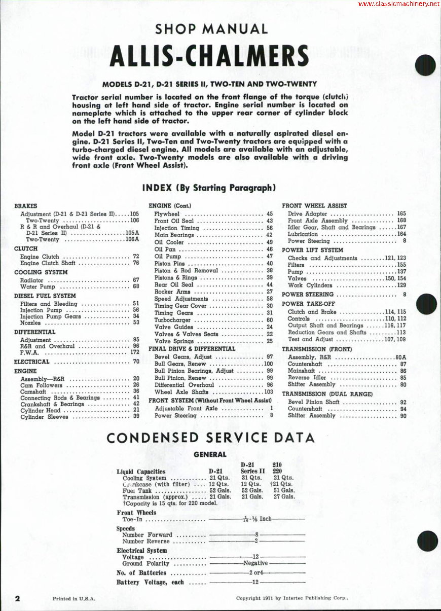
SHOP MANUAL
ALLIS-CHALMERS
MODELS D-21, D-21 SERIES II, TWO-TEN AND TWO-TWENTY
Tractor serial number is located on the front flange of the torque (clutch)
housing at left hand side of tractor. Engine serial number is located on
nameplate which is attached to the upper rear corner of cylinder block
on the left hand side of tractor.
Model D-21 tractors were available with a naturally aspirated diesel en-
gine. D-21 Series II, Two-Ten and Two-Twenty tractors are equipped with a
turbo-charged diesel engine. All models are available with an adjustable,
wide front axle. Two-Twenty models are also available with a driving
front axle (Front Wheel Assist).
INDEX (By Starting ParagrapK)
BRAKES
Adjustment (D-21 & D-21 Series ID 105
Two-Twenty 106
R&R and Overhaul (D-21 &
D-21 Series 11) 105A
Two-Twenty 106A
CLUTCH
Engine Clutch 72
Engine Clutch Shait 76
COOLING SYSTEM
Radiator 67
Water Pump 68
DIESEL FUEL SYSTEM
Filters and Bleeding 51
Injection Pump 56
Injection Pump Gears 34
Nozzles 53
DIFFERENTIAL
Adjustment 95
R&R and Overhaul 96
F.W.A 172
ELECTRICAL 70
ENGINE
Assembly—R&R 20
Cam Followers 26
Camshaft 36
Connecting Rods & Bearings 41
Crankshaft & Bearings 42
Cylinder Head 21
Cylinder Sleeves 39
ENGINE (Cont)
Flywheel 45
Front Oil Seal 43
Injection Timing 56
Main Bearings 42
o n Cooler 49
Oil Pan 46
Oil Pump 47
Piston Pins 40
Piston & Rod Removal 38
Pistons & Rings 39
Rear Oil Seal 44
Rocker Arms 27
Speed Adjustments 58
Timing Gear Cover 30
Timing Gears 31
Turbochargar 60
Valve Guides 24
Valves & Valves Seats 22
Valve Springs 25
FINAL DRIVE & DIFFERENTIAL
Bevel Gears, Adjust 97
Bull Gears, Renew 100
Bull Pinion Bearings, Adjust 99
Bull Pinion, Renew 99
Differential Overhaul 96
Wheel Axle Shafts 103
FRONT SYSTEM (Without Front Wheel Assist)
Adjustable Front Axle 1
Power Steering 8
FRONT WHEEL ASSIST
Drive Adapter 165
Front Axle Assembly 168
Idler Gear, Shaft and Bearings 167
Lubrication 164
Power Steering 8
POWER LIFT SYSTEM
Checks and Adjustments 12L 123
Filters .155
Pump 137
Valves 150,154
Work Cylinders 129
POWER STEERING 8
POWER TAKE-OFF
Clutch and Brake 114.115
Controls 110,112
Output Shaft and Bearings 116,117
Reduction Gears and Shafts 113
Test and Adjust 107,109
TRANSMISSION (FRONT)
Assembly, R&R 80A
Countershaft 87
Mainshaft 86
Reverse Idler 85
Shifter Assembly 80
TRANSMISSION (DUAL RANGE)
Bevel Pinion Shaft 92
Countershaft 94
Shifter Assembly 90
CONDENSED SERVICE DATA
GENERAL
Liquid Capacities D-21 Series II
Cooling System 21 Qts. 31 Qts.
Crmkcase (with filter) .... 12 Qts. 12 Qts.
Fuei Tank 52 Gals. 52 Gals,
Transmission (approx.) 21 Gals. 21 Gals.
tCapacity is 15 qts. for 220 model.
Front Wheels
Toe-In iV-% Inch-
Speeds
Number Forward 8
Number Reverse 2
Electrical System
Voltage ' 12
Ground Polarity Negative —
No. of Batteries 2or4——
Battery Yoltage, each 12
210
21 Qts.
t21 Qts.
51 Gals.
27 Gals.
Printed in U.S.A. Copyright 1971 by Intertec Publishing Corp.,
D-21, D'21 Series II. 210, 220 Paragraphs 1-5
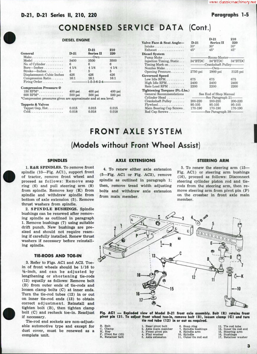
CONDENSED SERVICE DATA (Cont.)
DIESEL ENGINE
D-21 210
General D-21 SeHes II 220
Make Own
Model 3400 3500 3500
No. of Cylinder 6 6 6
Bore—Inches 4 1/4 4 ^4 41/4
Stroke—Inches 5 5 5
Displacement-Cubiclnches 426 426 426
Compression Ratio 16:1 16:1 16:1
Firing Order 1-5-3-6-2-4
Compression Pressure @
150 RPM* 400 psi 400 psi 400 psi
600 RPM* 500 psi 500 psi 500 psi
^Compression pressures given are approximate and at sea level.
Tappets & Valves
Tappet Gap, Hot 0.015 0.015 0.015
Cold 0.018 0.018 0.018
D-21 210
Valve Face & Seat Angle<- D-21 Series II 220
Intake 30'' 30* 30"
Exhaust 45" 45* 45"
Diesel System
Pump Make Roosa-Master
Injection Timing. Static . . . 34"BTDC 34"BTDC 34"BTDC
Timing Mark on Crankshaft Pulley
Nozzles Make Own
Opening Pressure 2750 psi 2900 psi 3125 psi
Governed Speed
Low Idle RPM 675 675 675
High Idle RPM 2400 2400 2400
Rate Load RPM 2200 2200 2200
Tightening Ibrques (Ft.-Lbs.)
General Recommendations See End of Shop Manual
Cylinder Head See Paragraph 21
Crankshaft Pulley 200-220 200-220 200-220
Flywheel 95-105 95-105 95-105
Main Bearing Cap Screws. 170-190 170-190 170-190
Rod Cap Screws See Paragraph 38
FRONT AXLE SYSTEM
(Models without Front Wheel Assist)
SPINDLES
1. K&R SPINDLES. To remove front
spindle (10—Fig. ACl), support front
of tractor, remove front wheel and
proceed as follows: Remove snap
ring (6) and pull steering arm (8)
from spindle. Remove key (K) from
spindle and withdraw spindle from
bottom of axle extension (5). Remove
thrust washers from spindle.
2. SPINDLE BUSHINGS. Spindle
bushings can be renewed after remov-
ing spindle as outlined in paragraph
1. Remove bushings (7) using suitable
drift punch. New bushings are pre-
sized and should not require ream-
ing if carefully installed. Renew thrust
washers if necessary before reinstall-
ing spindle.
TIE-RODS AND TOE-IN
3. Refer to Figs. ACl and AC2. Toe-
in of front wheels should be 1/16 to
Vs-inch, and can be adjusted by
lengthening or shortening tie-rods
(12) equally as follows: Remove bolt
(B) from outer ends of tie-rods and
loosen clamp bolts (C) at inner ends.
Turn the tie-rod tubes (12) in or out
on inner tie-rod ends (13) to obtain
correct adjustment. Reinstall and
tighten bolt (B), then tighten clamp
bolt (C) and recheck toe-in. Readjust
if necessary.
Tie-rod end sockets are non-adjust-
able automotive type and except for
dust cover, must be renewed as a
complete unit.
AXLE EXTENSIONS
4, To renew either axle extension
(5—Fig, ACl or Fig. AC2), remove
spindle as outlined in paragraph 1;
then, remove tread width adjusting
bolts and withdraw axle extension
from main member.
STEERING ARM
5. To renew the steering arm (15—
Fig. ACl) or steering arm bushings
(16), proceed as follows: Disconnect
steering cylinder piston rod and tie-
rods from the steering arm, then re-
move steering arm from pivot pin (P)
on the crossbar in front axle main
member.
17
Fig. ACl — Exploded view of Model D-21 front axle ossembly. Bolt (R) retains front
pivot pin (3). To ad|ust front wheel toe-in, remove boit (B), loosen clamp (C) and turn
tie rod tube (12) In or out as required.
B. Bolt
C. Clamp
K. Key
P. Pivot for (15)
R. Retainer bolt
1. Rear pivot bolt
2. Axle main member
3. Front pivot pin
4. Flat washer
5. Axle extension
6. Snap ring
7. Spindle bushings
8. Spindle arm
10. Spindle
11. Outer tie rod end
12. Tie rod tube
13. Inner tie rod end
15. Steering arm
16. Bushings
17. Retainer washer
3
Paragraphs 6-7
Drive the bushings (16) out of
steering arm using a suitable bushing
driver. New bushings are pre-sized
and should not require reaming if
carefully installed.
The steering arm pivot pin (P) is
an integral part of the axle center
(main) member and radius rod assem-
bly.
AXLE CENTER (MAIN) MEMBER
AND PIVOT PINS
6. The axle center (main) member
and the radius rods are welded one-
piece assembly (2—Fig. ACl or Fig.
AC2). The center member pivots on
a bolt (1) at rear end of assembly and
a pin (3) at front end. The bolt and
pin pivot in renewable bushings in the
clutch (torque) housing and in the
front support casting.
To renew the pivot bolt or pivot
pin, proceed as follows; Support trac-
tor under the torque housing so that
no weight is carried on the front axle.
Then, remove the retaining bolt (R—
Fig. ACl) and drive the front pivot
pin out towards front of tractor. The
plug (3—Fig. AC3) with lubricating
fitting will be driven out with pin.
Then, raise front of tractor until front
support is clear of axle and drive
bushing (2) out to rear with suitable
driver. New bushing is pre-sized and
should not require reaming if care-
fully installed. Install pivot pin and
retaining bolt, then drive the plug
(3) into front support with a hollow
driver so that plug is flush with cast-
ing.
To remove rear pivot bolt, support
rear (radius rod) end of axle main
member and remove cotter pin and
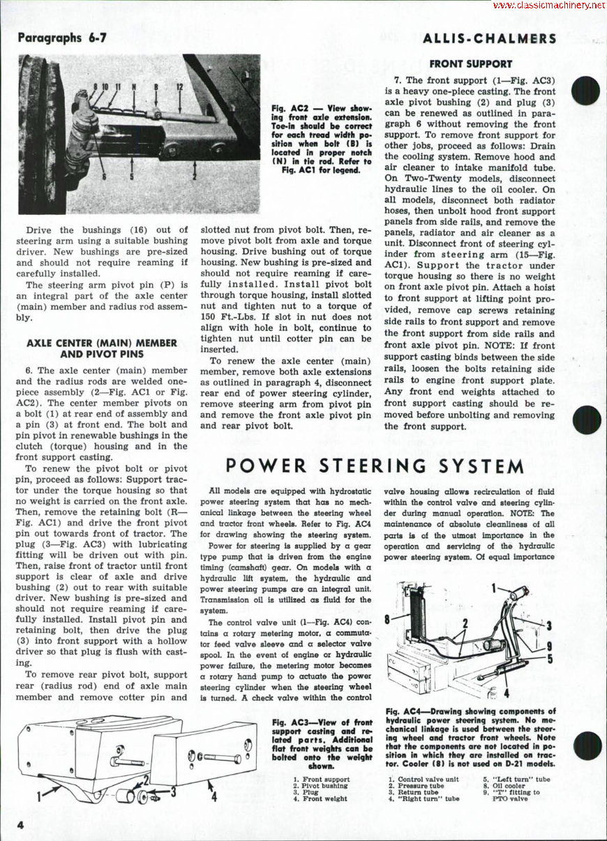
Fig. AC2 — View show-
ing front axie extension.
Toe-in should be correct
for each treod width po-
sition when bolt (B) is
iocated in proper notch
(N) in tie rod. Refer to
Fig. ACl for iegend.
slotted nut from pivot bolt. Then, re-
move pivot bolt from axle and torque
housing. Drive bushing out of torque
housing. New bushing is pre-sized and
should not require reaming if care-
fully installed. Install pivot bolt
through torque housing, install slotted
nut and tighten nut to a torque of
150 Ft.-Lbs. If slot in nut does not
align with hole in bolt, continue to
tighten nut until cotter pin can be
inserted.
To renew the axle center (main)
member, remove both axle extensions
as outlined in paragraph 4, disconnect
rear end of power steering cylinder,
remove steering arm from pivot pin
and remove the front axle pivot pin
and rear pivot bolt.
i^ ALLIS-CHALMBRS
FRONT SUPPORT
7. The front support (1—^Fig. AC3)
is a heavy one-piece casting. The front
axle pivot bushing (2) and plug (3)
can be renewed as outlined in para-
graph 6 without removing the front
support. To remove front support for
other jobs, proceed as follows: Drain
the cooling system. Remove hood and
air cleaner to intake manifold tube.
On Two-Twenty models, disconnect
hydraulic lines to the oil cooler. On
all models, disconnect both radiator
hoses, then unbolt hood front support
panels from side rails, and remove the
panels, radiator and air cleaner as a
unit. Disconnect front of steering cyl-
inder from steering arm (15—^Fig.
ACl). Support the tractor under
torque housing so there is no weight
on front axle pivot pin. Attach a hoist
to front support at lifting point pro-
vided, remove cap screws retaining
side rails to front support and remove
the front support from side rails and
front axle pivot pin. NOTE: If front
support casting binds between the side
rails, loosen the bolts retaining side
rails to engine front support plate.
Any front end weights attached to
front support casting should be re-
moved before unbolting and removing
the front support.
POWER STEERING SYSTEM
All models are equipped with hydrostatic
power steering system that has no mech-
anical linkage between the steering wheel
and tractor front wheels. Refer to Fig. AC4
for drawing showing the steering system.
Power for steering is supplied by a gear
type pump that is driven from the engine
timing (camshaft) gear. On models with a
hydraulic lift system, the hydraulic and
power steering pumps are an integral unit.
Transmission oU is utilized as fluid for the
system.
The control valve unit (1—Fig. AC4) con-
tains a rotary metering motor, a commuta-
tor feed valve sleeve and a selector valve
spool. In the event of engine or hydraulic
power failure, the metering motor becomes
a rotary hand pump to actuate the power
steering cylinder when the steering wheel
is turned. A check valve within the control
Fig. AC3—View of front
support easting and r^
iated parts. Additional
flat front weigiits can be
boited onto the weight
shown.
1. Front support
2. Pivot bushing
3. Plug
4. Front weight
valve housing allows redrculation of fluid
within the control valve and steering cylin-
der during manual operation. NOTE: The
maintenance of absolute cleanliness of all
parts is of the utmost importance in the
operation and servicing of the hydraulic
power steering system. Of equal importance
Fig. AC4—Drawing showing components of
hydrauiic power steering system. No me-
clionicoi linicage is used between the steer-
ing wheei and troctor front wheeis. Note
that the components are not located in po-
sition in which they are installed on trac-
tor. Cooier (8) is not used on D-21 modeis.
1. Control valve unit
2. Pressure tube
3. Return tube
4. "Right turn" tube
5. "Left turn" tube
8. Oil cooler
9. "T" fitting to
PTO valve
Q.21. D-21 Series II. 210, 220
Poragraphs 8-lOA
i8 the avoidance of nicks or hvms on any
of the working parts. Do not use cloth shop
towels in cleaning the system internal parts;
use only lint free power shop towels.
TROUBLE SHOOTING
8. Before attempting to adjust or
repair the power steering system, the
cause of any malfunction should be
located. Refer to the following para-
graphs for possible causes of power
steering system malfunction:
Irresrular or "Sticky" Steering. If
irregular or **sticky" feeling is noted
when turning the steering wheel with
forward motion of tractor stopped and
with engine running at rated speed,
or if steering wheel continues to ro-
tate after being turned and released,
foreign material in the power steering
fluid (transmission oil) is the prob-
able cause of trouble. Clean or renew
all hydraulic system filters. It may
be necessary to also drain the trans-
mission oil and refill with clean oil.
If trouble is not corrected, the power
steering valve assembly should be re-
moved and serviced; refer to para-
graph 12.
Steering Cylinder "Hesitates". If
steering cylinder appears to pause in
travel when steering wheel is being
turned steadily probable cause of
trouble is air trapped in the power
steering cylinder. Bleed the cylinder
as outlined in paragraph 9.
Slow Steering. Slow steering may
be caused by low oil flow from pump.
Check time required for full stroke
travel of power steering cylinder; first
with tractor weight on the front
wheels, then with front end of trac-
tor supported by a jack. If time be-
tween the two checks varies consider-
ably, overhaul the power steering
pump as outlined in paragraph 139.
Loss of Power. Loss of steering
power may be caused by system re-
lief setting being too low. Check and
adjust relief valve setting as outlined
in paragraph lOA or lOB.
System Overheats. Overheating of
system may be caused by neutral (by-
pass) pressure being too high. Check
neutral pressure as outlined in para-
graph lOA. If neutral pressure is ex-
cessive, check for obstructions in sys-
tem such as kinked tube, etc. If neu-
tral pressure is erratic, check for bind-
ing of control valve shaft, spool and/
or sleeve.
LUBRICATION AND BLEEDING
9. Transmission lubricating oil is
utilized as the power steering fluid;
refer to note preceding paragraph 80.
The power steering system is usually
self-bleeding. With engine running at
high idle speed, cycle system through
several full strokes of the cylinder. In
some cases, it may be necessary to
loosen connections at cylinder to bleed
trapped air.
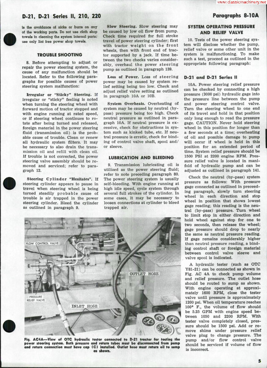
Fig. AC4A—View of OTC hydraulic fesfer connected to D-21 fracfor for testing the
power steering system. Both pressure and return tubes must be disconnected from pump
and return connection must have cap CO installed. Outlet hose must return oil to sump
OS shown.
SYSTEM OPERATING PRESSURE
AND RELIEF VALVE
10. Tests of the power steering sys-
tem will disclose whether the pump,
relief valve or some other unit in the
system is malfunctioning. To make
such a test, proceed as outlined in the
appropriate following paragraph:
D-21 and D-21 Series II
10A. Power steering relief pressure
can be checked by connecting a high
pressure (3000 psi) hydraulic gage into
the pressure line between the pump
and power steering control valve.
Turn the steering wheel to one end
of its travel and hold in that position
only long enough to read the pressure
gage. CAUTION. Never hold steering
wheel in this position for longer than
a few seconds at a time; overheating
of oil and possible damage to pump
will occur if wheel is held in this
position for an extended period of
time. System relief pressure should be
1500 PSI at 2200 engine RPM. Pres-
sure relief valve is located in mani-
fold of hydraulic pump and can be
adjusted as outlined in paragraph 141.
Check the neutral (by-pass) system
pressure as follows: With pressure
gage connected as outlined in preceed-
ing paragraph, slowly turn steering
wheel in each direction and stop
wheel in position that shows lowest
gage reading; this reading is the neu-
tral (by-pass) pressure. Turn wheel
to limit stop in either direction and
hold wheel against stop for one to
two seconds, then release the wheel;
gage pressure should drop to nearly
the same as neutral pressure reading.
If gage remains considerably higher
than neutral pressure reading, a bind-
ing control shaft or foreign material
between control valve sleeve and
valve spool is indicated.
A hydraulic tester (such as OTC
Y81-21) can be connected as shown in
Fig. AC 4A to check pump volume
and relief pressure. The outlet hose
should be routed to sump as shown.
With engine operating at approxi-
mately 1600 RPM, close the tester
valve until pressure is approximately
1200 psi. When oil temperature reaches
100* F., the volume of flow should
be 5.25 GPM with engine speed be-
tween 1050 and 2200 RPM. With
tester valve completely closed, pres-
sure should be 1500 psi. Add or re-
move shims under pressure relief
valve plug to change pressure. The
pump and/or flow control valve
should be serviced if volume of flow
is incorrect.
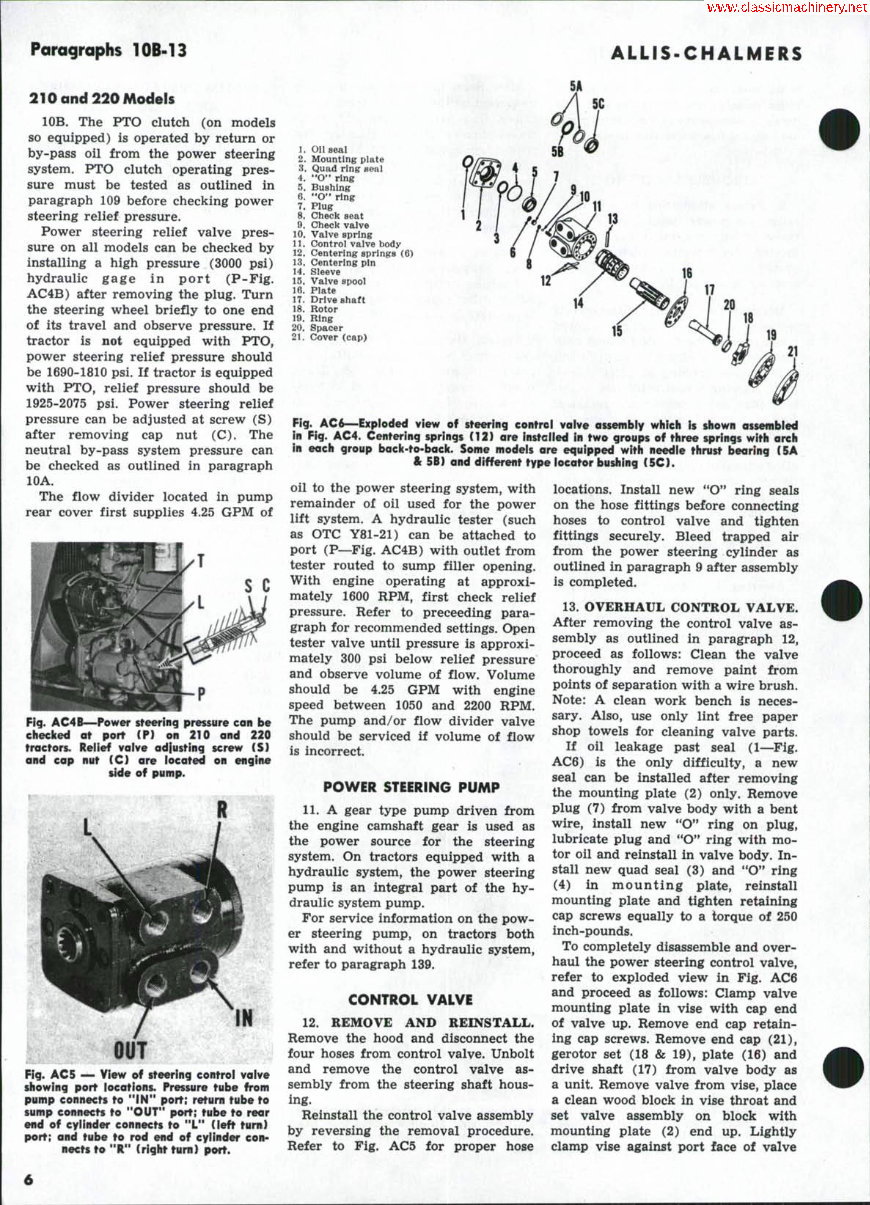
Paragraphs 10B-13
ALLIS-CHALMERS
210 and 220 Models
lOB. The PTO clutch (on models
so equipped) is operated by return or
by-pass oil from the power steering
system. PTO clutch operating pres-
sure must be tested as outlined in
paragraph 109 before checking power
steering relief pressure.
Power steering relief valve pres-
sure on all models can be checked by
installing a high pressure (3000 psi)
hydraulic gage in port (P-Fig.
AC4B) after removing the plug. Turn
the steering wheel briefly to one end
of its travel and observe pressure. If
tractor is not equipped with PTO,
power steering relief pressure should
be 1690-1810 psi. If tractor is equipped
with PTO, relief pressure should be
1925-2075 psi. Power steering relief
pressure can be adjusted at screw (S)
after removing cap nut (C). The
neutral by-pass system pressure can
be checked as outlined in paragraph
lOA.
The flow divider located in pump
rear cover first supplies 4.25 GPM of
Fig. AC4B—Power sfeering pressure can be
checiced at port (P) on 210 and 220
tractors. Reiief vaive adiusting screw (S)
and cap nut (C) are iocated on engine
Me of pump.
Fig. AC5 — View of steering controi vaive
showing port locations. Pressure tube from
pump connects to " i N " port; return tube to
sump connects to "OUT" port; tube to rear
end of cylinder connects to "L" (left turn)
port; and tube to rod end of cyiinder con-
nects to "R" (right turn) port.
1.
2.
3.
4.
5.
6.
7.
8.
9.
10.
11.
12.
13.
14.
15.
16.
17.
18.
Id.
20.
21.
Oil seal
Mounting plate
Qua4 ling eeal
"0" ring
Bushing
**0" ring
Plug
Check seat
Check valve
Valve spring
Control valve body
Centering springs (6)
Centering pin
Sleeve
Valve spool
Plate
Drive shaft
Rotor
Ring
Spacer
Cover (cap)
vr
Fig. AC6—Exploded view of steering control valve assembly which is shown assembied
in Fig. AC4. Centering springs (12) are instGiied in two groups of three springs with arch
in each group back-to-bacic. Some modeis are equipped with needie thrust bearing (5A
& 5B) and different type locator bushing (5C).
oil to the power steering system, with
remainder of oil used for the power
lift system. A hydraulic tester (such
as OTC Y81-21) can be attached to
port (P—Fig. AC4B) with outlet from
tester routed to sump filler opening.
With engine operating at approxi-
mately 1600 RPM, first check relief
pressure. Refer to preceeding para-
graph for recommended settings. Open
tester valve until pressure is approxi-
mately 300 psi below relief pressure
and observe volume of flow. Volume
should be 4.25 GPM with engine
speed between 1050 and 2200 RPM.
The pump and/or flow divider valve
should be serviced if volume of flow
is incorrect.
POWER STEERING PUMP
11. A gear type pump driven from
the engine camshaft gear is used as
the power source for the steering
system. On tractors equipped with a
hydraulic system, the power steering
pump is an integral part of the hy-
draulic system pump.
For service information on the pow-
er steering pump, on tractors both
with and without a hydraulic system,
refer to paragraph 139.
CONTROL VALVE
12. REMOVE AND REINSTALL.
Remove the hood and disconnect the
four hoses from control valve. Unbolt
and remove the control valve as-
sembly from the steering shaft hous-
ing.
Reinstall the control valve assembly
by reversing the removal procedure.
Refer to Fig. AC5 for proper hose
locations. Install new "O" ring seals
on the hose fittings before connecting
hoses to control valve and tighten
fittings securely. Bleed trapped air
from the power steering cylinder as
outlined in paragraph 9 after assembly
is completed.
13. OVERHAUL CONTROL VALVE.
After removing the control valve as-
sembly as outlined in paragraph 12,
proceed as follows: Clean the valve
thoroughly and remove paint from
points of separation with a wire brush.
Note: A clean work bench is neces-
sary. Also, use only lint free paper
shop towels for cleaning valve parts.
If oil leakage past seal (1—Fig.
AC6) is the only difficulty, a new
seal can be installed after removing
the mounting plate (2) only. Remove
plug (7) from valve body with a bent
wire, install new "O" ring on plug,
lubricate plug and *'O" ring with mo-
tor oil and reinstall in valve body. In-
stall new quad seal (3) and "O" ring
(4) in mounting plate, reinstall
mounting plate and tighten retaining
cap screws equally to a torque of 250
inch-pounds.
To completely disassemble and over-
haul the power steering control valve,
refer to exploded view in Fig. AC6
and proceed as follows: Clamp valve
mounting plate in vise with cap end
of valve up. Remove end cap retain-
ing cap screws. Remove end cap (21),
gerotor set (18 & 19), plate (16) and
drive shaft (17) from valve body as
a unit. Remove valve from vise, place
a clean wood block in vise throat and
set valve assembly on block with
mounting plate (2) end up. Lightly
clamp vise against port face of valve
D-21. D-21 Series II, 210. 220
Paragrapks 14-15
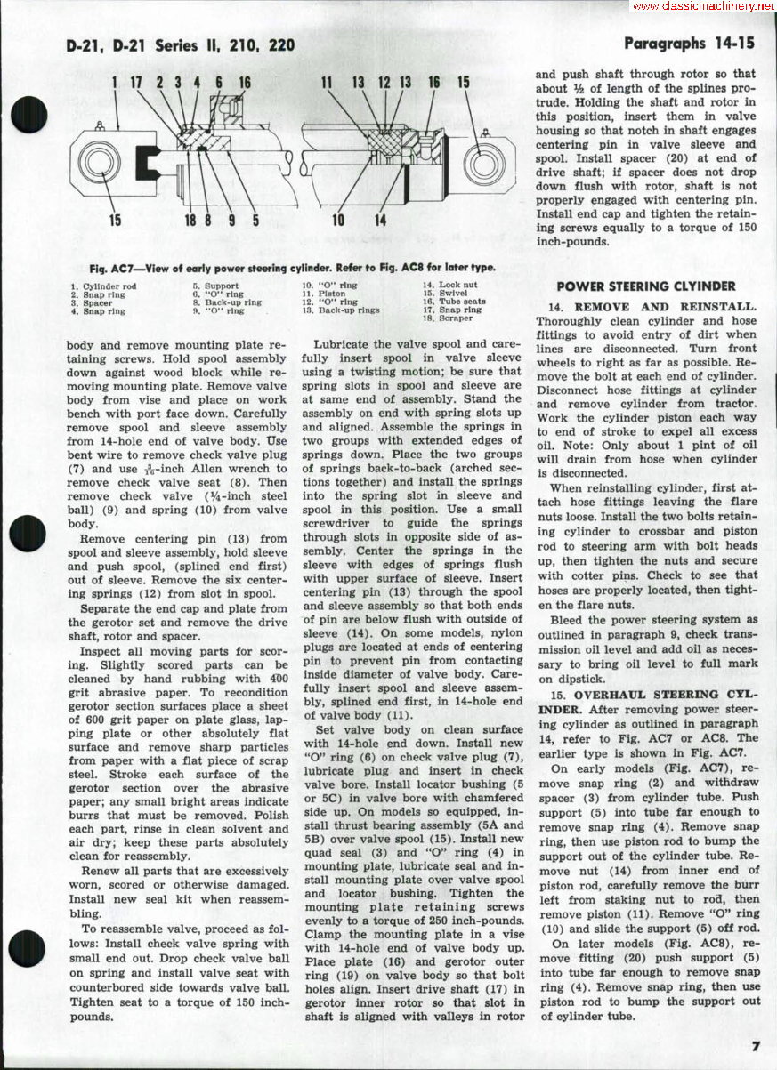
1 17 2 3 4 6 16 11 13 12 13 16 15
15 16 8 9 5
Fig. AC7—View of eorly power steering cylinder. Refer to Fig. AC8 for later type.
1. Cylinder rod
2. Snap ring
3. Spacer
4. Snap ring
5. Support
G. *'O" ring
8. Back-up ring
9. "O** ring
body and remove mounting plate re-
taining screws. Hold spool assembly
down against wood block while re-
moving mounting plate. Remove valve
body from vise and place on work
bench with port face down. Carefully
remove spool and sleeve assembly
from 14-hole end of valve body. Use
bent wire to remove check valve plug
(7) and use ^^-inch Allen wrench to
remove check valve seat (8). Then
remove check valve (V4-inch steel
ball) (9) and spring (10) from valve
body.
Remove centering pin (13) from
spool and sleeve assembly, hold sleeve
and push spools (splined end first)
out of sleeve. Remove the six center-
ing springs (12) from slot in spool.
Separate the end cap and plate from
the gerotor set and remove the drive
shaft, rotor and spacer.
Inspect all moving parts for scor-
ing. Slightly scored parts can be
cleaned by hand rubbing with 4D0
grit abrasive paper. To recondition
gerotor section surfaces place a sheet
of 600 grit paper on plate glass, lap-
ping plate or other absolutely flat
surface and remove sharp particles
from paper with a flat piece of scrap
steel. Stroke each surface of the
gerotor section over the abrasive
paper; any small bright areas indicate
burrs that must be removed, Polish
each part, rinse in clean solvent and
air dry; keep these parts absolutely
clean for reassembly.
Renew all parts that are excessively
worn, scored or otherwise damaged.
Install new seal kit when reassem-
bling.
To reassemble valve, proceed as fol-
lows: Install check valve spring with
small end out. Drop check valve ball
on spring and install valve seat with
counterbored side towards valve ball.
Tighten seat to a torque of 150 inch-
pounds.
10. "O" ring
11. Piston
12. "O" ring
13. BacU-up rings
14. Lock nut
15. Swivei
16. Tube seats
17. Snap ring
18. Scraper
Lubricate the valve spool and care-
fully insert spool in valve sleeve
using a twisting motion; be sure that
spring slots in spool and sleeve are
at same end of assembly. Stand the
assembly on end with spring slots up
and aligned. Assemble the springs in
two groups with extended edges of
springs down. Place the two groups
of springs back-to-back (arched sec-
tions together) and install the springs
into the spring slot in sleeve and
spool in this position. Use a small
screwdriver to guide the springs
through slots in opposite side of as-
sembly. Center the springs in the
sleeve with edges of springs flush
with upper surface of sleeve. Insert
centering pin (13) through the spool
and sleeve assembly so that both ends
of pin are below flush with outside of
sleeve (14). On some models, nylon
plugs are located at ends of centering
pin to prevent pin from contacting
inside diameter of valve body. Care-
fully insert spool and sleeve assem-
bly, splined end first, in 14-hole end
of valve body (11).
Set valve body on clean surface
with 14-hole end down. Install new
"O" ring (6) on check valve plug (7),
lubricate plug and insert in check
valve bore. Install locator bushing (5
or 5C) in valve bore with chamfered
side up. On models so equipped, in-
stall thrust bearing assembly (5A and
5B) over valve spool (15). Install new
quad seal (3) and *'O" ring (4) in
mounting plate, lubricate seal and in-
stall mounting plate over valve spool
and locator bushing. Tighten the
mounting plate retaining screws
evenly to a torque of 250 inch-pounds.
Clamp the mounting plate in a vise
with 14-hole end of valve body up.
Place plate (16) and gerotor outer
ring (19) on valve body so that bolt
holes align. Insert drive shaft (17) in
gerotor inner rotor so that slot in
shaft is aligned with valleys in rotor
and push shaft through rotor so that
about Vi of length of the splines pro-
trude. Holding the shaft and rotor in
this position, insert them in valve
housing so that notch in shaft engages
centering pin in valve sleeve and
spool. Install spacer (20) at end of
drive shaft; if spacer does not drop
down flush with rotor, shaft is not
properly engaged with centering pin.
Install end cap and tighten the retain-
ing screws equally to a torque of 150
inch-pounds.
POWER STEERING CLYINDER
14. REMOVE AND REINSTALL.
Thoroughly clean cylinder and hose
fittings to avoid entry of dirt when
lines are disconnected. Turn front
wheels to right as far as possible. Re-
move the bolt at each end of cylinder.
Disconnect hose fittings at cylinder
and remove cylinder from tractor.
Work the cylinder piston each way
to end of stroke to expel all excess
oil. Note: Only about 1 pint of oil
will drain from hose when cylinder
is disconnected.
When reinstalling cylinder, first at-
tach hose fittings leaving the flare
nuts loose. Install the two bolts retain-
ing cylinder to crossbar and piston
rod to steering arm with bolt heads
up, then tighten the nuts and secure
with cotter pins. Check to see that
hoses are properly located, then tight-
en the flare nuts.
Bleed the power steering system as
outlined in paragraph 9, check trans-
mission oil level and add oil as neces-
sary to bring oil level to full mark
on dipstick,
15. OVERHAUL STEERING CYL-
INDER. After removing power steer-
ing cylinder as outlined in paragraph
14, refer to Fig. AC7 or AC8. The
earlier type is shown in Fig, AC7.
On early models (Fig. AC7), re-
move snap ring (2) and withdraw
spacer (3) from cylinder tube. Push
support (5) into tube far enough to
remove snap ring (4), Remove snap
ring, then use piston rod to bump the
support out of the cylinder tube. Re-
move nut (14) from inner end of
piston rod, carefully remove the burr
left from staking nut to rod, then
remove piston (11). Remove **O" ring
(10) and slide the support (5) off rod.
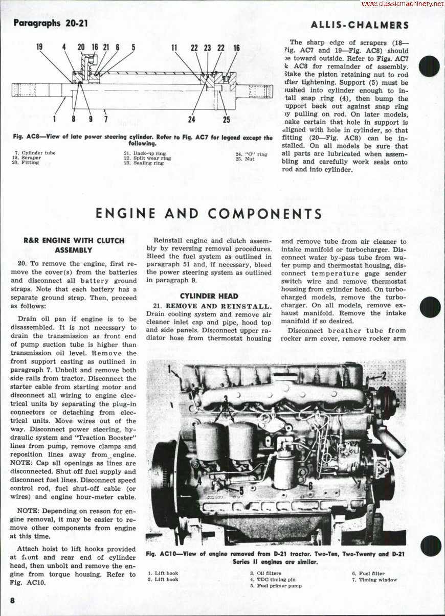
On later models (Fig. AC8), re-
move fitting (20) push support (5)
into tube far enough to remove snap
ring (4). Remove snap ring, then use
piston rod to bump the support out
of cylinder tube.
ParograpKs 20-21
ALLIS-CHALMBRS
19 21 6 5 11 22 23 22 IB
Fig. AC8—View
7. Cylinder tube
19. Scraper
20. FlttlnK
25
steering cyiinder. Refer to Fig. AC7 for iegend except tiie
foiiowing.
21. Back-'ip ring
22. Split wear ring
23. Sealing ring
24. "O" ring
25. Nut
The sharp edge of scrapers (18—
?ig. AC7 and 19—Fig. AC8) should
3e toward outside. Refer to Figs. AC7
k AC8 for remainder of assembly.
Stake the piston retaining nut to rod
ifter tightening. Support (5) must be
)ushed into cylinder enough to in-
tall snap ring (4), then bump the
upport back out against snap ring
)y pulling on rod. On later models,
nake certain that hole in support is
aligned with hole in cylinder, so that
fitting (20—Fig. AC8) can be in-
stalled. On all models be sure that
all parts are lubricated when assem-
bling and carefully work seals onto
rod and into cylinder.
ENGINE AND COMPONENTS
R&R ENGINE WITH CLUTCH
ASSEMBLY
20. To remove the engine, first re-
move the cover(s) from the batteries
and disconnect all battery ground
straps. Note that each battery has a
separate ground strap. Then, proceed
as follows:
Drain oil pan if engine is to be
disassembled. It is not necessary to
drain the transmission as front end
of pump suction tube is higher than
transmission oil level. Remove the
front support casting as outlined in
paragraph 7. Unbolt and remove both
side rails from tractor. Disconnect the
starter cable from starting motor and
disconnect all wiring to engine elec-
trical units by separating the plug-in
connectors or detaching from elec-
trical units. Move wires out of the
way. Disconnect power steering, hy-
draulic system and "Traction Booster**
lines from pump, remove clamps and
reposition lines away from^ engine.
NOTE: Cap all openings as lines are
disconnected. Shut off fuel supply and
disconnect fuel lines. Disconnect speed
control rod, fuel shut-off cable (or
wires) and engine hour-meter cable.
NOTE: Depending on reason for en-
gine removal, it may be easier to re-
move other components from engine
at this time.
Attach hoist to lift hooks provided
at front and rear end of cylinder
head, then unbolt and remove the en-
gine from torque housing. Refer to
Fig. ACIO.
Reinstall engine and clutch assem-
bly by reversing removal procedures.
Bleed the fuel system as outlined in
paragraph 51 and, if necessary, bleed
the power steering system as outlined
in paragraph 9.
CYLINDER HEAD
21. REMOVE AND REINSTALL.
Drain cooling system and remove air
cleaner inlet cap and pipe, hood top
and side panels. Disconnect upper ra-
diator hose from thermostat housing
and remove tube from air cleaner to
intake manifold or turbocharger. Dis-
connect water by-pass tube from wa-
ter pump and thermostat housing, dis-
connect temperature gage sender
switch wire and remove thermostat
housing from cylinder head. On turbo-
charged models, remove the turbo-
charger. On all models, remove ex-
haust manifold. Remove the intake
manifold if so desired.
Disconnect breather tube from
rocker arm cover, remove rocker arm
Fig. ACIO—View of engine removed from D-21 tractor. Two-Ten, Two-Twenty and D-21
Series II engines are simiiar.
1. Lift hook
2. Lift hook
3. Oii filters
4. TDO timing pin
5. Fuel primer pump
6. Fuel filter
7. Timing window
8
D-21, D.21 Series II, 210, 220
Paragrophs 22-23
cover, remove oil supply line to rock-
er arm assembly and equally loosen
and remove the rocker arm assembly
retaining cap screws. Lift off rocker
arm assembly and remove the push
rods. Disconnect fuel return line at
front injector and cap all openings
as each line is disconnected.
NOTE: Although not required for removal
of the cylinder head, it is recommended that
the fuel injector assemblies be removed
from cylinder head at this time. The in-
jector nozzle tips protrude through the flat
bottom surface of the cylinder head and, if
injectors are not removed, extreme care
must be taken when removing and handling
the removed cylinder head.
Remove the cylinder head retain-
ing cap screws and carefully pry cyl-
inder head up off of the dowel pins
(DP—Fig. ACll) located at front and
rear of cylinder block. Lift cylinder
head from tractor.
When reinstalling cylinder head, be
sure that gasket surfaces of cylinder
head and block are clean and free of
burrs. Check cylinder liner standout
as outlined in paragraph 39, Place
new gasket with side marked "THIS
SIDE DOWN" against cylinder block
and be sure gasket is properly lo-
cated on the two dowel pins. Note:
Do not apply grease or gasket sealer
to gasket surfaces, block or cylinder
head; new gasket is treated with phe-
nolic sealer. Locate fire rings around
cylinder sleeves then position cylin-
der head on the dowel pins. Lubricate
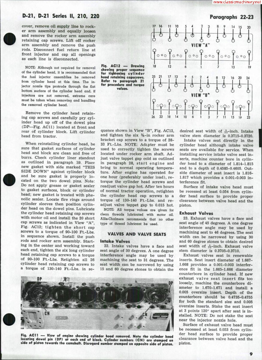
the cylinder head retaining cap screws
with motor oil and install the 20 short
cap screws as indicated in View "A",
Fig, AC12; tighten the short cap
screws to a torque of 90-100 Ft.-Lbs.
in sequence shown. Install the push
rods and rocker arm assembly. Start-
ing in the center and working toward
each end, tighten the six long cylinder
head retaining cap screws to a torque
of 90-100 Ft.-Lbs. Retighten all 26
cylinder head retaining cap screws to
a torque of 130-140 Ft,-Lbs, in se-
17 16
8 ? 14 15 20
Fig. ACl 2 — Drawing
showing proper sequence
for tightening cylinder
head retaining capscrews.
Refer to paragraph 21
for procedure and torque
values.
VIEW "
^ f oQo I oQoToQo T oOo foOo | ,
18 14 10 6 1
15 19 23
quence shown in View "B'*, Fig. AC 12,
and tighten the six %-in rocker arm
bracket cap screws to a torque of 28-
33 Ft.-Lbs. NOTE: Adt.pter must be
used to correctly tighten the screws
located under rocker arm shaft. Ad-
just valve tappet gap cold as outlined
in paragraph 28, start engine and
bring to normal operating tempera-
ture. After engine has operated for
one hour (preferably under load), re-
torque the cylinder head screws and
readjust valve gap hot. After ten hours
of normal tractor operation, retighten
the cylinder head cap screws to a
torque of 130-140 Ft.-Lbs, and re-
adjust valve tappet gap to 0.015 hot,
NOTE: All torque values are given ior
clean threads lubricated with motor oil.
Allis-Chalmers recommends that no other
type of thread lubricant be used,
VALVES AND VALVE SEATS
Intake Valves
22. Intake valves have a face and
seat angle of 30 degrees, A one degree
interference angle may be used by
machining the seat to 31 degrees. The
seat width can be narrowed by using
15 and 60 degree stones to obtain the
Fig. ACn — View of engine showing cyiinder head removed. Note the cylinder head
locating dowei pin CDP) at each end of biock. Cylinder numbers (CN) ore stamped on
side of piston towards the camshaft. Disregard number stamped on opposite side of piston.
desired seat width of ^-inch. Intake
valve stem diameter is 0,3715-0.3720,
Intake valves seat directly in the
cylinder head although intake valve
seats are available for service. When
installing service intake valve seat in-
serts, machine counter bore in cylin-
der head to a diameter of 1.814-1,815
and to a depth of 0.4585-0.4605, Out-
side diameter of seat insert is 1,816-
1,817 which provides a 0.001-0,003 in-
terference fit.
Surface of intake valve head must
be recessed at least 0.054 from cylin-
der head surface to provide proper
clearance between valve head and the
piston.
Exhaust Valves
23, Exhaust valves have a face and
seat angle of 45 degrees. A one degree
interference angle may be used by
machining seat to 46 degrees. The seat
width can be narrowed by using 30
and 60 degree stones to obtain desired
seat width of ^-inch. Exhaust valve
stem diameter is 0,3705-0,3710.
Exhaust valves seat in renewable
inserts. Seat insert diameter of 1.667-
1.668 provides a 0.001-0,003 interfer-
ence fit in the 1,665-1.666 diameter
counterbore in cylinder head. If new
exhaust valve seat insert fits too
loosely, machine the counterbore di-
ameter to 1,670-1,671 and install a
0,005 oversize insert. Depth of the
counterbore should be 0,4735-0,4755
for both the standard size and 0.005
oversize inserts. Stake the seat insert
at 3 points 120° apart after seat is in-
stalled. NOTE: Do not stake the seat
near the injector nozzle hole.
Surface of exhaust valve head must
be recessed at least 0.053 from cylin-
der head surface to provide proper
clearance between valve head and the
piston.
Paragraphs 24-27 ALLIS-CHALMERS
VALVE GUIDES
24. Renew valve guides when stem
to guide clearance exceeds 0.0035 on
intake valves or 0.0055 on exhaust
valves. Desired stem to guide clear-
ance is 0.001-0.0015 for intake valves
and 0.002-0.0025 for exhaust valves.
Intake and exhaust valve guides are
interchangeable. When installing new
guides, press new guides in from bot-
tom of cylinder head. The top of in-
take valve guides should be 25/32-
inch from counterbore around guide
and bottom of guide should be ap-
proximately 1%-inches from cylinder
head gasket surface. The top of ex-
haust valve guides should be 1^-
inches from counterbore around guide
and bottom of guide should be approx-
imately lH-inches from cylinder head
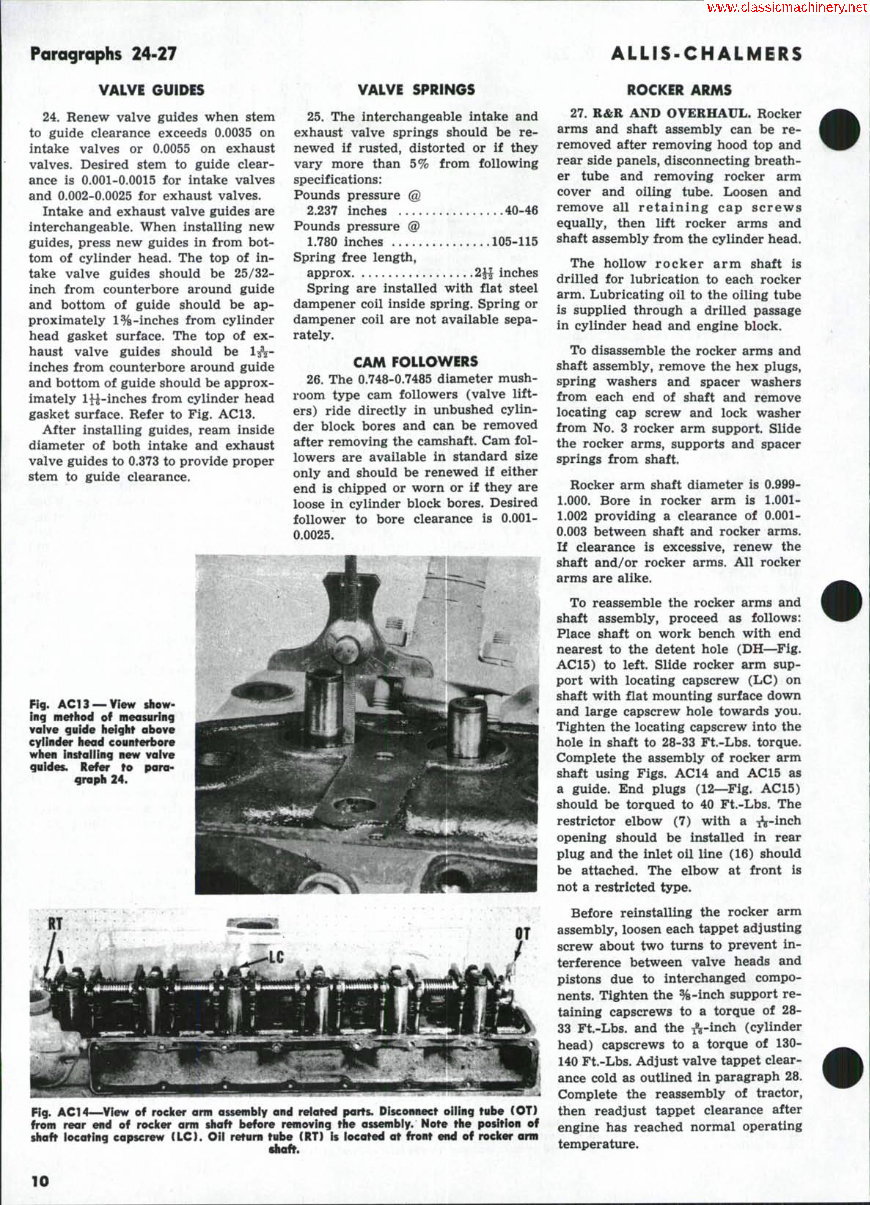
gasket surface. Refer to Fig. AC13.
After installing guides, ream inside
diameter of both intake and exhaust
valve guides to 0.373 to provide proper
stem to guide clearance.
VALVE SPRINGS
25. The interchangeable intake and
exhaust valve springs should be re-
newed if rusted, distorted or if they
vary more than 5% from following
specifications:
Pounds pressure @
2,237 inches 40-46
Pounds pressure @
1.780 inches 105-115
Spring free length,
approx 2JJ inches
Spring are installed with flat steel
dampener coil inside spring. Spring or
dampener coil are not available sepa-
rately.
CAM FOLLOWERS
26. The 0.748-0.7485 diameter mush-
room type cam followers (valve lift-
ers) ride directly in unbushed cylin-
der block bores and can be removed
after removing the camshaft. Cam fol-
lowers are available in standard size
only and should be renewed if either
end is chipped or worn or if they are
loose in cylinder block bores. Desired
follower to bore clearance is 0.001-
0.0025.
Fig. AC13 —yr«w $how-
inq method of measuring
vaive guide height above
eyiinder head counterbore
when instaiiing new valve
guides. Refer to para-
graph 24.
Fig. ACT4—^View of roeicer arm assembiy and related parts. Disconnect oUing tube (OT)
from rear end of roeicer arm shaft before removing the assembiy. Note the position of
shaft locating capscrew (LC). Oii return tube (RT) is iocated at front end of roeicer arm
ROCKER ARMS
27. R&R AND OVERHAUL. Rocker
arms and shaft assembly can be re-
removed after removing hood top and
rear side panels, disconnecting breath-
er tube and removing rocker arm
cover and oiling tube. Loosen and
remove all retaining cap screws
equally, then lift rocker arms and
shaft assembly from the cylinder head.
The hollow rocker arm shaft is
drilled for lubrication to each rocker
arm. Lubricating oil to the oiling tube
is supplied through a drilled passage
in cylinder head and engine block.
To disassemble the rocker arms and
shaft assembly, remove the hex plugs,
spring washers and spacer washers
from each end of shaft and remove
locating cap screw and lock washer
from No. 3 rocker arm support. Slide
the rocker arms, supports and spacer
springs from shaft.
Rocker arm shaft diameter is 0.999-
1.000. Bore in rocker arm is 1.001-
1.002 providing a clearance of 0.001-
0.003 between shaft and rocker arms.
If clearance is excessive, renew the
shaft and/or rocker arms. All rocker
arms are alike.
To reassemble the rocker arms and
shaft assembly, proceed as follows:
Place shaft on work bench with end
nearest to the detent hole (DH—^Fig.
AC15) to left. Slide rocker arm sup-
port with locating capscrew (LC) on
shaft with flat mounting surface down
and large capscrew hole towards you.
Tighten the locating capscrew into the
hole in shaft to 28-33 Ft.-Lbs. torque.
Complete the assembly of rocker arm
shaft using Figs. AC 14 and AC 15 as
a guide. End plugs (12—Fig. AC15)
should be torqued to 40 Ft.-Lbs. The
restrictor elbow (7) with a ^-inch
opening should be installed in rear
plug and the inlet oil line (16) should
be attached. The elbow at front is
not a restricted type.
Before reinstalling the rocker arm
assembly, loosen each tappet adjusting
screw about two turns to prevent in-
terference between valve heads and
pistons due to interchanged compo-
nents. Tighten the %-inch support re-
taining capscrews to a torque of 28-
33 Ft.-Lbs. and the A-inch (cylinder
head) capscrews to a torque of 130-
140 Ft.-Lbs. Adjust valve tappet clear-
ance cold as outlined in paragraph 28.
Complete the reassembly of tractor,
then readjust tappet clearance after
engine has reached normal operating
temperature.
10
D-2T. D-21 Series II, 210. 220 Paragraphs 28-30
VALVE CLEARANCE
28. Because of the limited clearance
between the head of the valve and
top of piston, valve clearance (Tappet
Gap) should be checked and adjusted
only with engine stopped. After any
service to valve system, valve clear-
ance should be adjusted cold before
engine is started. Valve clearance
should be rechecked with engine at
operating temperature.
Clearance Cold—
Inlet & Exhaust 0.018 in.
Clearance Hot—
Inlet & Exhaust 0.015 in.
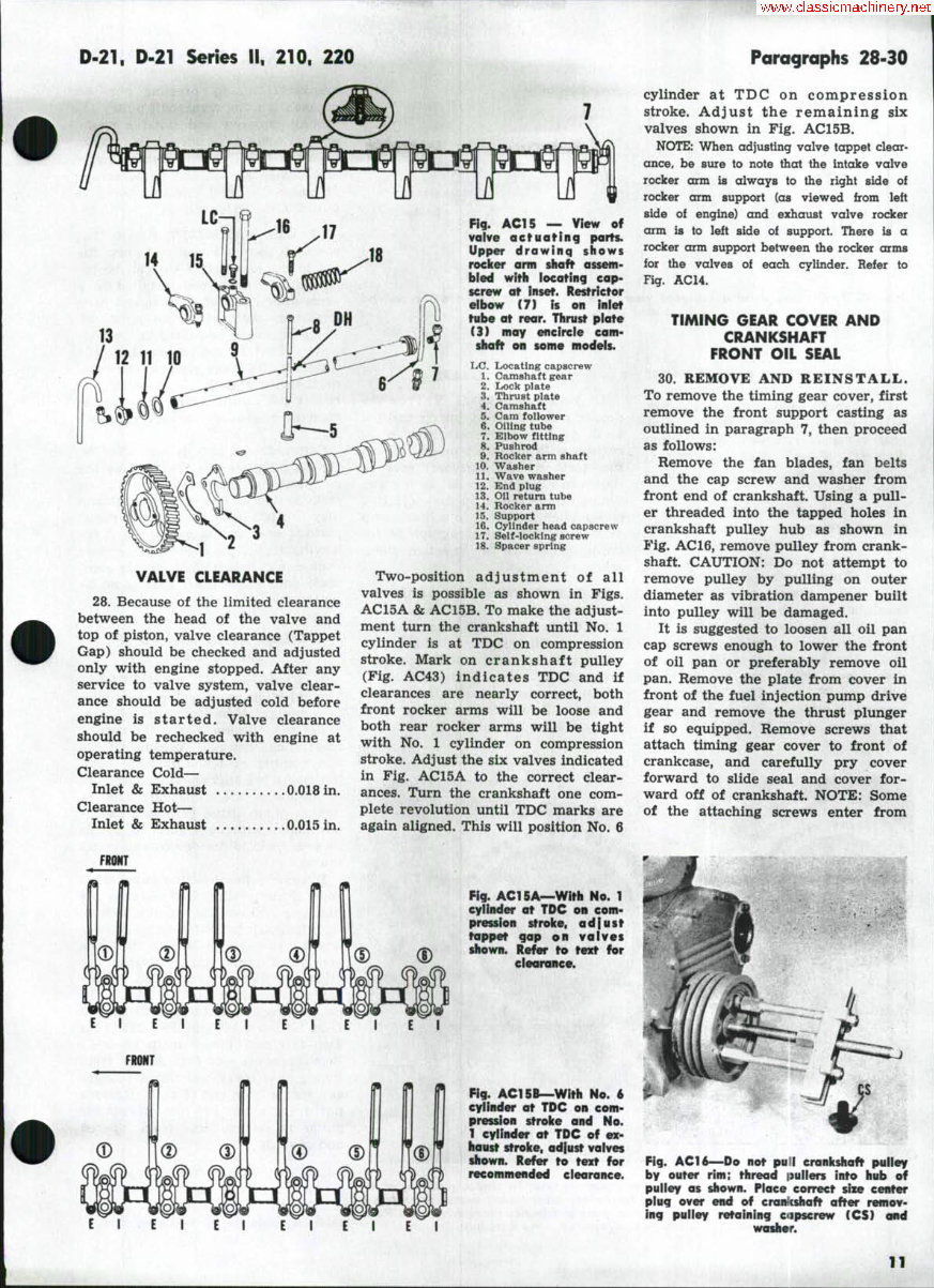
Fig. AC15 — View of
vaive octuaffnq parts.
Upper drawinq shows
rocker arm shaft assem-
bled with locating cap-
screw at inset. Restrictor
elbow (7) U on inlet
tube at rear. Thrust plate
(3) may encircie cam-
shaft on some modeis.
Locating capscrew
Camshaft gear
Lock plate
Thrust plate
Camshaft
Cam follower
Oiling tube
Elbow fitting
Pushrod
Rocker arm shaft
Washer
Wave washer
End plug
on return tube
Rocker arm
Support
Cylinder head capscrew
Self-lock ing screw
Spacer spring
Two-position adjustment of all
valves is possible as shown in Figs.
AC15A & AC15B. To make the adjust-
ment turn the crankshaft until No. 1
cylinder is at TDC on compression
stroke. Mark on crankshaft pulley
(Fig. AC43) indicates TDC and if
clearances are nearly correct, both
front rocker arms will be loose and
both rear rocker arms will be tight
with No. 1 cylinder on compression
stroke. Adjust the six valves indicated
in Fig. AC15A to the correct clear-
ances. Turn the crankshaft one com-
plete revolution until TDC marks are
again aligned. This will position No. 6
cylinder at TDC on compression
stroke. Adjust the remaining six
valves shown in Fig. AC15B.
NOTE: When adjusting valve tappet clear-
ance, be sure to note that the intake valve
rocker arm is always to the right side of
rocker arm support (as viewed trom left
side ol engine) and exhaust valve rocker
arm is to left side of support. There is a
rocker arm support between the rocker arms
for the valves of each cylinder. Refer to
Fig. AC14.
TIMING GEAR COVER AND
CRANKSHAFT
FRONT OIL SEAL
30. REMOVE AND REINSTALL.
To remove the timing gear cover, first
remove the front support casting as
outlined in paragraph 7, then proceed
as follows:
Remove the fan blades, fan belts
and the cap screw and washer from
front end of crankshaft. Using a pull-
er threaded into the tapped holes in
crankshaft pulley hub as shown in
Fig. AC 16, remove pulley from crank-
shaft. CAUTION: Do not attempt to
remove pulley by pulling on outer
diameter as vibration dampener built
into pulley will be damaged.
It is suggested to loosen all oil pan
cap screws enough to lower the front
of oil pan or preferably remove oil
pan. Remove the plate from cover in
front of the fuel injection pump drive
gear and remove the thrust plunger
if so equipped. Remove screws that
attach timing gear cover to front of
crankcase, and carefully pry cover
forward to slide seal and cover for-
ward off of crankshaft. NOTE: Some
of the attaching screws enter from
FRONT
E l E l E l E l E l
E I E I E I E 1 E 1
Fig. AC15A—With No. T
cylinder at TDC on com-
pression stroke, a d I u s t
toppet gap on valves
shown. Refer to text for
clearance.
Fig. AC15B—With No. 6
cylinder at TDC on com-
pression stroke and No.
1 cylinder at TDC of ex-
haust sTroke, adiust valves
shown. Refer to text for
recommended clearance.
E I
Fig. ACT6~Do not pull crankshaft pulley
by outer rim; thread iiuliers into hub of
pulley as shown. Place correct size center
plug over end of cranicshaft after remov-
ing pulley retaining oipscrew (CS) and
washer.
11
You're Reading a Preview
What's Included?
 Lifetime Access
Fast Download Speeds
Online & Offline Access
Access PDF Contents & Bookmarks
Full Search Facility
Print one or all pages of your manual
$52.99
Allis Chalmers G Tractor Shop Service Repair & OPERATOR Owner Manual & IMPLEMENTS Parts -4- Manuals -
Viewed 15 Times Today

What's Included?
Lifetime Access
Fast Download Speeds
Online & Offline Access
Access PDF Contents & Bookmarks
Full Search Facility
Print one or all pages of your manual
$52.99

Secure transaction
What's Included?
Lifetime Access
Fast Download Speeds
Online & Offline Access
Access PDF Contents & Bookmarks
Full Search Facility
Print one or all pages of your manual
Description
- Allis Chalmers AC G Tractor Shop Service Repair Manual and Operator Owner Manual and Implements Operator Maintenance ILP -4- Manuals
- The following 4 Manuals are included:
- Allis Chalmers Model G Tractor Dealers Service Manual
- Allis Chalmers Model G Tractor Operating Instructions Maintenance & Repair Parts Illustrations Manual
- Allis Chalmers Model G Tractor Implements Setting-Up Directions, Operation, Maintenance & Repair Parts Illustrations Manual
- Allis Chalmers G Tractor Shop Manual: this is an After-Market Manual
- These invaluable technical manuals include all needed instructions to maintain, service and operate your equipment using detailed diagrams and manufacturers specifications.
- Navigation is simple with convenient chapter bookmarks and ability to search by keyword. Print out entire manual or just what you'll be working on!
- INSTANT - NO WAITING
- LANGUAGE: English
- PED FILES
- COMPATIBLE: Win/ Mac
- SEARCHABLE - BOOKMARKED - INDEXED
- Fully Bookmarked chapters for easy navigation allowing you to identify the exact service repair procedures in the quickest time possible.
- Detailed illustrations, exploded diagrams, drawings and photos guide you through every service repair procedure.
- Completely Indexed, Bookmarked and Searchable!
- SERVICE MANUAL SECTIONS INCLUDE:
- Air Cleaner
- Ammeter
- Battery
- ...
- Wiring Diagram
- OPERATORS MANUAL SECTIONS INCLUDE:
- Specifications
- Lubrication Guide
- Before Starting the Tractor
- ...
- Safety Suggestions
- IMPLEMENTS MANUAL SECTIONS INCLUDE:
- General
- Master Hand Lift
- ...
- Storage
- SHOP MANUAL SECTIONS INCLUDE:
- Belt Pulley
- Brakes
- ...
- Transmission
- Lots of pictures, diagrams and illustrations
- Great for tune-ups, regular maintenance or repairs. All technical details and step-by-step instructions you will need are included!
- JUST CLICK THE GREEN & WHITE - NOW BUTTON - at the Top Right-Hand Side of this Page & get this Manual - IMMEDIATELY
- We have Thousands of Manuals - email us about any you might need.


