Allis Chalmers D15 series 2 Tractor Workshop Service Manual
What's Included?
Lifetime Access
Fast Download Speeds
Online & Offline Access
Access PDF Contents & Bookmarks
Full Search Facility
Print one or all pages of your manual
SHOP MANUAL ALLIS-CHALMERS MODELS D.14. D.15. D-15 SERIES II. D-17. D-17 SERIES III AND D-17 SERIES IV Model D-14 troctors were available in singie wheel tricycle, dual wheel tricycle and adfustabie axle versions with non-diesel engines only. Model D-15 tractors were avaiiable in single wheel tricycle, dual wheel tricycle, adjustable or heavy duty non-adjustable front axle versions with either 175 cubic inch diesel or 149 cubic inch non-diesel engines Model D-15 Series II tractors are avaiiable in single wheel tricycle, dual wheel tricycle, adjustable or heavy duty non-adjustable front axle versions with either 175 cubic inch diesel or 160 cubic inch non- diesel engine. D-17. D-17 Series ill and D-17 Series iV tractors are available in singie wheel tricycle, adjustable or heavy duty non-adjustable front axle versions with either 262 cubic inch diesei or 226 cubic inch non-diesel engine. INDEX (By Starting Paragraph) BELT PULLEY 218 BRAKES D-14.and D-IS 209 I>.17 (Band/Diac Type) 215 D.17 (Shoe Type) 212 CARBXmETOR GafloUne 99 CUJTCH Engine Clutch 149 Engine Clutch Shalt 156 "Power-Director" Clutch 160 Shuttle autch 170 COOLING SYSTEM Radiator 135 Water Pump 136,140 DIESEL FUEL SYSTEM Energy CeUs 128 Filters and Bleeding 113 Injection Pump 124 Noixles 115 Quick Checks 112 ELECTRICAL Spark Plugs 141 Distributor 142 Generator 148 Starting Motor 148 Voltage Regulator 148 Wiring Diagrams Page 88 2 ,r.- ENGINE (DIESEL) Assembly, R&R 34 Cam Followers i^ 48 Camshaft 68 Connecting Rods & Bearings ... 78 Crankshaft & Bearings 81 Cylinder Head 37 Cylinder Sleeves 73 nywheel 89 Front OU Seal 86 Main Bearings 81 Oil Pan 92 Oil Pump 97 Piston Pins 78 Piston & Rod Removal 71 Pistons & Rings 73 Rear Oil Seal 87 Rocker Anus 52 Speed Adjustment .. 127 Timing Gear Cover 56 Timing Gears 61 Valve Guides 43 Valves & Valve Seats 39 Valve Springs 45 ENGINE (NON-DIESEL) Assembly, R&R 33 Com Followers 47 Camshaft 65, 66 Connecting Rods & Bearings . 77 Crankshaft & Bearings 79/80 Cylinder Block 88 Cylinder Head 35, 36 Cylinder Sleeves 72 nywheel 89 Front OU Seal 82, 84 Governor 132, 134 Ignition Timing 145 Main Bearings 79, 80 OU Pan 90, 91 OU Pump 93, 95 PUton Kns ..74, 75 Piston & Rod Removal 69, 70 Pistons & Rings 72 Rear OU Seal 83, 85 Rocker Arms 49, 50 Spark Plugs 141 Speed Adjustment 129, 133 Timing Gear Cover 53 Timing Gears 58 Valve Guides 41, 42 Valves & Valve Seats 38 Valve Springs 44
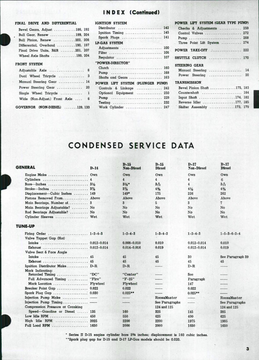
INDEX (Continued) FINAL DRIVE AND DIFFERENTIAL Bevei Gears, Adjust 186. 192 Bull Gear, Renew 199, 204 Bull Pinion. Renew 202. 206 Differential, Overhaul 190, 197 Final Drive Units, R&R 201, 207 Wheel Axle Shaits 199. 204 FRONT SYSTEM Adjustable Axle 6 Dual Wheel Tricycle 3 Manual Steering Gear 14 Power Steering Gear 20 Single Wheel Tricycle 1 Wide (Non-Adjust.) Front Axle 6 GOVERNOR (NON-DIESEL) 129.133 IGNITION SYSTEM Distributor 142 Ignition Timing 145 Spark Plugs 141 LP-GAS SYSTEM Adjustments 100 FUter • 106 Regulator 107 "POWER-DIRECTOR" Clutch 160 Pump 168 Shaits and Gears 163 POWER LIFT SYSTEM (PLUNGER PXJMP) Controls & Linkage 242 Optional Equipment 250 Pump 229 Testing 232 Work Cyiinder 247 POWER LIFT SYSTEM (GEAR TYPE PUMP) Checks & Adjustments 259 Control Valves 272 Pump 268 Three Point Lift System 274 POWER TAKE-OFF 222 SHUTTLE CLUTCH 170 STEERING GEAR Manual Steering 14 Power Steering 20 TRANSMISSION Bevel Pinion Shaft 175, 183 Countershaft 184 Input Shaft 174, 182 Reverse Idler 177, 185 Shifter Assembly 173, 179 CONDENSED SERVICE DATA GENERAL D-H Engine Make Own Cylinders 4 Bore—Inches 3% Stroke—Inches 3% Displacement—Cubic Inches 149 Pistons Removed From Above Main Bearings, Number oi 3 Main Bearings Adjustable? No Rod Bearings Adjustable? No Cylinder Sleeves Wet TUNE-UP Firing Order 1-2-4-3 Valve Tappet Gap (Hot) Intake 0.012-0.014 Exhaust 0.012-0.014 Valve Seat & Face Angle Intake 45 Exhaust 45 Ignition Distributor Make D-R Mark Indicating: Retarded Timing "DC" Full Advanced Timing \ "Fire" Mark Location Flywheel Breaker Point Gap 0.022 Spark Plug Gap 0.030 Injection Pump Make Injection Pump Timing Compression Pressure at Cranking Speed—Gasoline or Diesel , 135 Low Idle RPM 450 High Idle RPM 2025 FuU Load RPM 1650 D-U Non-Diesel Own 4 3% 149* Above 3 No No Wet 1-2-4-3 0.008-0.010 0.014-0.016 45 45 Flywheel 0.022 0.025** 160 550 2200 2000 D-15 Diesel Own 4 4% 175 Above 5 No No Wet 1-3-4-2 0.010 0.019 45 45 RoosaMeister See Pars.graphs 124 and 125 325 625 2200 2000 D-17 Non-Diesel Own 4 4 4% 226 Above 3 No No Wet 1-2-4-3 0.012-0.014 0.012-0.014 30 45 D-P QAA OKStS Par^raph 147 0.022 (>.O25** 145 400 1975 1650 D-17 Diesel Own 6 3A 4% 262 Above 7 No No Wet 1-5-3-6-2-4 0.010 0.019 See Paragraph 39 45 RoosaMaster See Paragraphs 124 and 125 385 625 1985 1650 * Series II D-15 engine cylinder bore 3H inches; displacement is 160 cubic inches. **Spark plug gap for D-15 and D-17 LP-Gas models should bo 0.020.
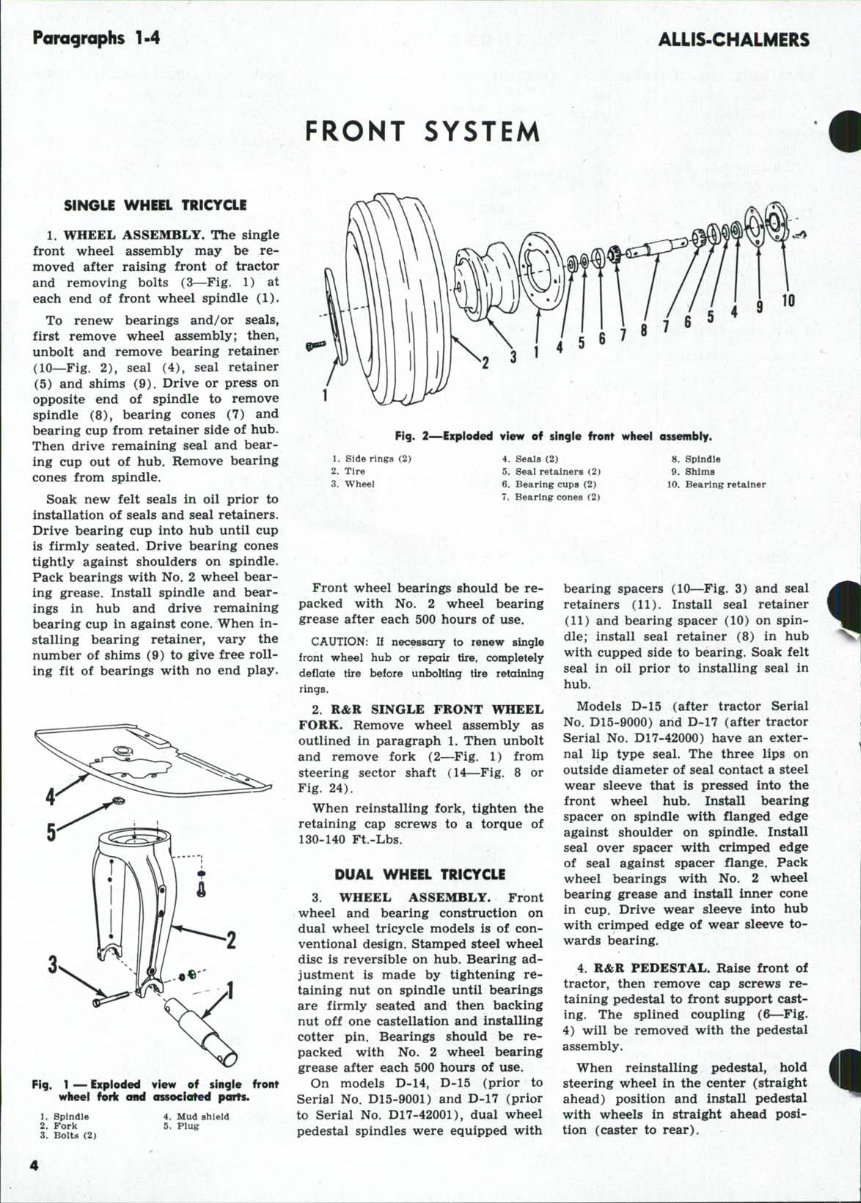
Poragraphs 1-4 ALLIS-CHALMERS FRONT SYSTEM SINGLE WHEEL TRICYCLE L WHEEL ASSEMBLY. The single front wheel assembly may be re- moved after raising front of tractor and removing bolts (3—Fig. 1) at each end of front wheel spindle (1). To renew bearings and/or seals, first remove wheel assembly; then, unbolt and remove bearing retainer (10—Fig. 2), seal (4), seal retainer (5) and shims (9). Drive or press on opposite end of spindle to remove spindle (8), bearing cones (7) and bearing cup from retainer side of hub. Then drive remaining seal and bear- ing cup out of hub. Remove bearing cones from spindle. Soak new felt seals in oil prior to installation of seals and seal retainers. Drive bearing cup into hub until cup is firmly seated. Drive bearing cones tightly against shoulders on spindle. Pack bearings with No. 2 wheel bear- ing grease. Install spindle and bear- ings in hub and drive remaining bearing cup in against cone. When in- stalling bearing retainer, vary the number of shims (9) to give free roll- ing fit of bearings with no end play. 3 Fig. 1 — Exploded view of single front wheel fork ond ossocioted ports. 10 Fig. 2—Exploded view of singie front wheel assembiy. 1. 2. 3. Side rings (2) Tire Wheel 4. 5. 6. 7. Seals (2) Seal retainers (2) Bearing cups (2) Bearing cones (2) 8. Spindle 9. Shims 10. Bearing retainer 1. Spindle 2. Fork 3. Bolts (2) 4. Mud shield 5. Plug Front wheel bearings should be re- packed with No. 2 wheel bearing grease after each 500 hours of use. CAUTION: If necessary to renew single front wheel hub or repair tire, completely deflate tire before unbolting tire retaining rings. 2. R&R SINGLE FRONT WHEEL FORK. Remove wheel assembly as outlined in paragraph 1. Then unbolt and remove fork (2—Fig. 1) from steering sector shaft (14—Fig. 8 or Fig. 24). When reinstalling fork, tighten the retaining cap screws to a torque of 130-140 Ft.-Lbs. DUAL WHEEL TRICYCLE 3. WHEEL ASSEMBLY. Front wheel and bearing construction on dual wheel tricycle models is of con- ventional design. Stamped steel wheel disc is reversible on hub. Bearing ad- justment is made by tightening re- taining nut on spindle until bearings are firmly seated and then backing nut off one castellation and installing cotter pin. Bearings should be re- packed with No. 2 wheel bearing grease after each 500 hours of use. On models D-14, D-15 (prior to Serial No. D15-9001) and D-17 (prior to Serial No. D17-42001), dual wheel pedestal spindles were equipped with bearing spacers (10—Fig. 3) and seal retainers (11). Install seal retainer (11) and bearing spacer (10) on spin- dle; install seal retainer (8) in hub with cupped side to bearing. Soak felt seal in oil prior to installing seal in hub. Models D-15 (after tractor Serial No. D15-9000) and D-17 (after tractor Serial No. D17-42000) have an exter- nal lip type seal. The three lips on outside diameter of seal contact a steel wear sleeve that is pressed into the front wheel hub. Install bearing spacer on spindle with flanged edge against shoulder on spindle. Install seal over spacer with crimped edge of seal against spacer flange. Pack wheel bearings with No. 2 wheel bearing grease and install inner cone in cup. Drive wear sleeve into hub with crimped edge of wear sleeve to- wards bearing. 4. R&R PEDESTAL. Raise front of tractor, then remove cap screws re- taining pedestal to front support cast- ing. The splined coupling (6—Fig. 4) will be removed with the pedestal assembly. When reinstalling pedestal, hold steering wheel in the center (straight ahead) position and install pedestal with wheels in straight ahead posi- tion (caster to rear).
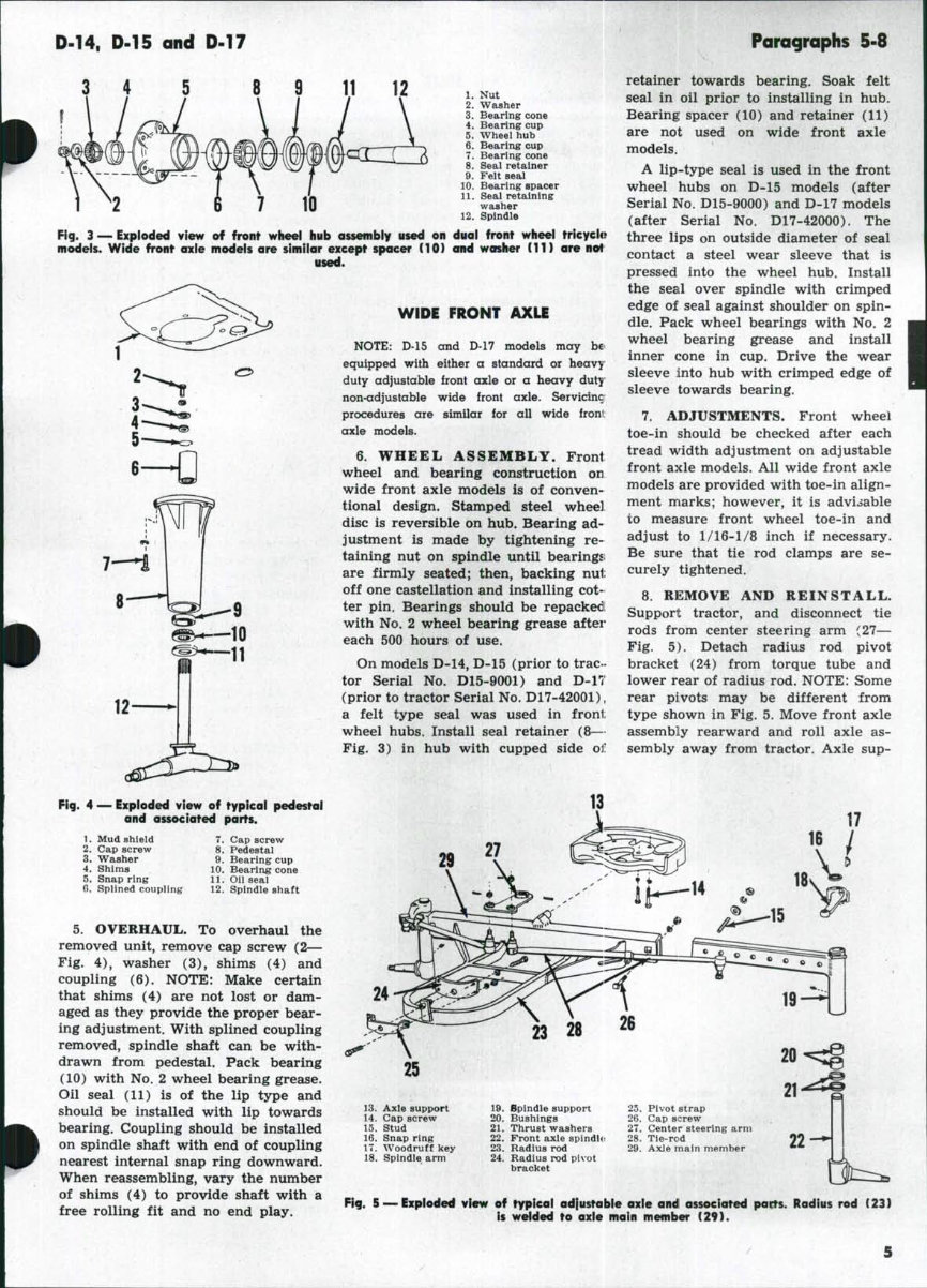
D-14, D-15 and D-17 Paragraphs 5-8 3 4 7 10 1. Nut 2. Washer 3. Bearing cone 4. Bearing cup 5. Wheel hub 6. Bearing cup 7. Bearing cone 8. Seal retainer 9. Felt seal 10. Bearing spacer 11. Seal retaining washer 12. Spindle Fig. 3 — Exploded view of front wheel hub assembly used on dual front wheel tricycle models. Wide front axle models are similor except spacer (10) and washer (11) are nof used. WIDE FRONT AXLE NOTE: D-15 and D-17 models may equipped with either a standard or duty adjustable front axle or a heavy non-adjustable wide front axle. Servicinc procedures are similar for all wide froni: axle models. 6. WHEEL ASSEMBLY. Front wheel and bearing construction on wide front axle models is of conven- tional design. Stamped steel wheel disc is reversible on hub. Bearing ad- justment is made by tightening re- taining nut on spindle until bearingsi are firmly seated; then, backing nut off one castellation and installing cot- ter pin. Bearings should be repackedl with No. 2 wheel bearing grease aftei' each 500 hours of use. On models D-14, D-15 (prior to trac- tor Serial No. D15-9001) and D-17 (prior to tractor Serial No. D17-42001), a felt type seal was used in froni; wheel hubs. Install seal retainer (8— Fig. 3) in hub with cupped side oir. retainer towards bearing. Soak felt seal in oil prior to installing in hub. Bearing spacer (10) and retainer (11) are not used on wide front axle models. A lip-type seal is used in the front wheel hubs on D-15 models (after Serial No. D15-9000) and D-17 models (after Serial No. D17-42000). The three lips on outside diameter of seal contact a steel wear sleeve that is pressed into the wheel hub. Install the seal over spindle with crimped edge of seal against shoulder on spin- dle. Pack wheel bearings with No. 2 wheel bearing grease and install inner cone in cup. Drive the wear sleeve into hub with crimped edge of sleeve towards bearing. 7, ADJUSTMENTS. Front wheel toe-in should be checked after each tread width adjustment on adjustable front axle models. All wide front axle models are provided with toe-in align- ment marks; however, it is advisable to measure front wheel toe-in and adjust to 1/16-1/8 inch if necessary. Be sure that tie rod clamps are se- curely tightened. 8. REMOVE AND REINSTALL. Support tractor, and disconnect tie rods from center steering arm (27— Fig. 5). Detach radius rod pivot bracket (24) from torque tube and lower rear of radius rod. NOTE: Some rear pivots may be different from type shown in Fig. 5. Move front axle assembly rearward and roll axle as- sembly away from tractor. Axle sup- Fig. 4 — Exploded view of typical pedestqt and associated parts. 1. Mud shield 2. Cap screw 3. Washer 4. Shims 5. Snap ring G. Splined coupling 7. Cap screw 8. Pedestal 9. Bearing cup 10. Bearing cone 11. Oil seal 12. Spindle shaft 5. OVERHAUL. To overhaul the removed unit, remove cap screw (2— Fig. 4), washer (3), shims (4) and coupling (6). NOTE: Make certain that shims (4) are not lost or dam- aged as they provide the proper bear- ing adjustment. With splined coupling removed, spindle shaft can be with- drawn from pedestal. Pack bearing (10) with No. 2 wheel bearing grease. Oil seal (11) is of the lip type and should be installed with lip towards bearing. Coupling should be installed on spindle shaft with end of coupling nearest internal snap ring downward. When reassembling, vary the number of shims (4) to provide shaft with a free rolling fit and no end play. 29 25 13. Axle support 14. Cap screw 15. Stud 16. Snap ring 17. Woodruff key 18. Spindle arm 19. 20. 21. 22. 23. Bpindle support Bushings Thrust washers Front axle spindles Radius rod 24. Radius rod pivot bracket 25. Pivot strap 26. Cap screw 27. Center steering arm 28. Tie-rod 29. Axle main member 22 — 5 — Expieded view of rypical ad|iistable axle andl associated pacts. Radius rod (23) is welded to axle main member (29).
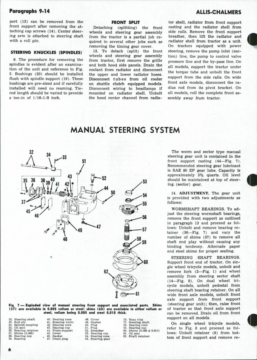
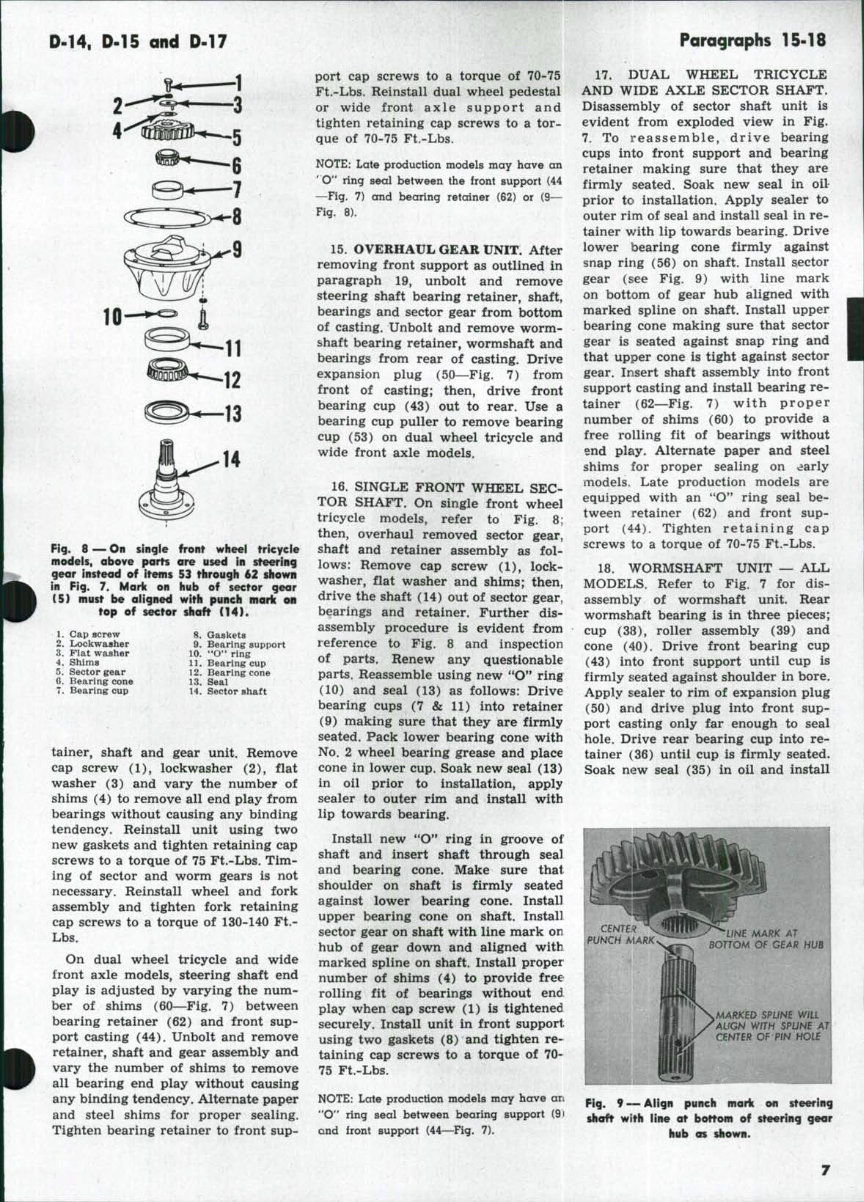
Paragraphs 9-14 ALLIS-CHALMERS port (13) can be removed from the front support after removing the at- taching cap screws (14). Center steer- ing arm is attached to steering shaft with a roll pin. STEERING KNUCKLES (SPINDLES) 9. The procedure for removing the spindles is evident after an examina- tion of the unit and reference to Fig. 5. Bushings (20) should be installed flush with spindle support (19). These bushings are pre-sized and if carefully installed will need no reaming. Tie- rod length should be varied to provide a toe-in of 1/16-1/8 inch. FRONT SPLIT Detaching (splitting) the front wheels and steering gear assembly from the tractor is a partial job re- quired in several other jobs such as removing the timing gear cover. 13. To detach (split) the front wheels and steering gear assembly from tractor, first remove the grille and both hood side panels. Drain the coolant from radiator and disconnect the upper and lower radiator hoses. Disconnect t u b e s from oil cooler on shuttle clutch equipped models. Disconnect wiring to headlamps if mounted on radiator shell. Unbolt the hood center channel from radia- tor shell, radiator from front support casting and the radiator shell from side rails. Remove the front support breather, then lift the radiator and radiator shell from tractor as a unit. On tractors equipped with power steering, remove the pump inlet (suc- tion) line, the pump to control valve pressure line and the by-pass line. On all models, support the tractor under the torque tube and unbolt the front support from the side rails. On wide front axle models, disconnect the ra- dius rod from its pivot bracket. On all models, roll the complete front as- sembly away from tractor. MANUAL STEERING SYSTEM Fig. 7 — Exploded view of moniiol steering front support and ossociated ports. Shims (37) ore avoilobie in 0.005 veiium or steel; shims (60) ore ovoiloble in either velium or steei. veiium being 0.005 and steei 0.010 thicic. .'J2. Steering shaft 33. Roll pin 34. Splined coupling 35. Oil seal 36. Bearing retainer 37. Shims (0.005) 38. Bearing cup 89. Bearing 40. Bearing cone 41. Steering worm 42. Bearing cone 43. Bearing cup 44. Front support 45. Cover 46. Gasket 47. Drain plug 48. Cover 49. Gasket 50. Plug 51. Plug 52. Breather 53. Bearing cup 54. Bearing cone 55. Steering gear 56. Snap ring o7. Steering shaft 58. Bearing cone 59. Bearing cup 60. Shims (0.005 & 0.010) 61. Oil seat 62. Shaft retainer The worm and sector type manual steering gear unit is contained in the front support casting (44—Fig. 7). Recommended steering gear lubricant is SAE 80 EP gear lube. Capacity is approximately 3% quarts. Oil level should be maintained at top of steer- ing, (sector) gear. 14. ADJUSTMENT. The gear unit is provided with two adjustments as follows: WORMSHAFT BEARINGS. To ad- just the steering wormshaft bearings, remove the front support as outlined in paragraph 13 and proceed as fol- lows: Unbolt and remove bearing re- tainer (36—Fig. 7) and vary the number of shims (37) to remove all shaft end play without causing any binding tendency. Alternate paper and steel shims for proper sealing. STEERING SHAFT BEARINGS. Support front end of tractor. On sin- gle wheel tricycle models, unbolt and remove fork (2—Fig. 1) and wheel assembly from steering sector shaft (14—Fig. 8). On dual wheel tri- cycle models, unbolt pedestal from steering shaft bearing retainer. On all wide front axle models, unbolt front axle support from front support (steering gear unit); then, ra^e front of tractor so that front axle support can be removed. Drain oil from front support on all models. On single wheel tricycle models, refer to Fig. 8 and proceed as fol- lows: Unbolt retainer (9) from bot- tom of front support and remove re-
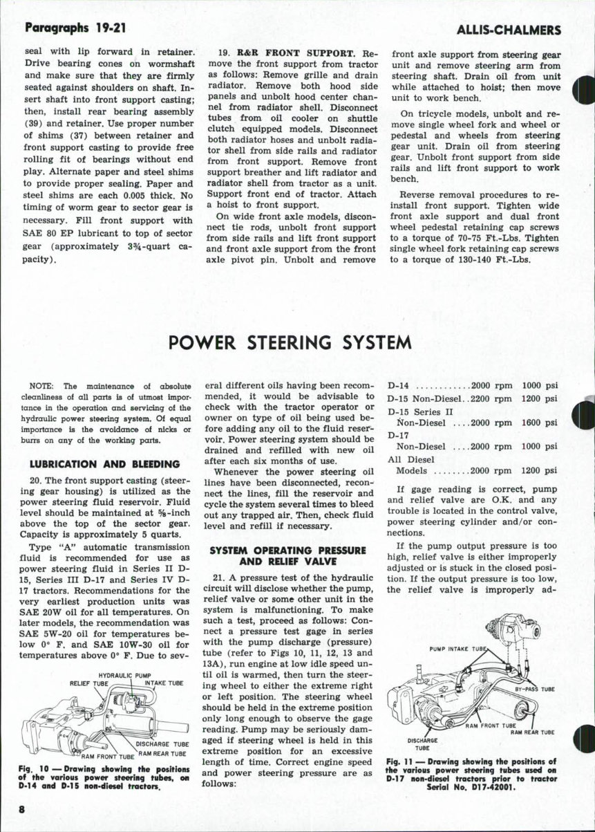
Paragraphs 19-21 seal with lip forward in retainer. Drive bearing cones on wormshaft and make sure that they are firmly seated against shoulders on shaft. In- sert shaft into front support casting; then, install rear bearing assembly (39) and retainer. Use proper number of shims (37) between retainer and front support casting to provide free rolling fit of bearings without end play. Alternate paper and steel shims to provide proper sealing. Paper and steel shims are each 0.005 thick. No timing of worm gear to sector gear is necessary. Fill front support with SAE 80 EP lubricant to top of sector gear (approximately 3%-quart ca- pacity). 19. R&R FRONT SUPPORT. Re- move the front support from tractor as follows: Remove grille and drain radiator. Remove both hood side panels and unbolt hood center chan- nel from radiator shell. Disconnect tubes from oil cooler on shuttle clutch equipped models. Disconnect both radiator hoses and unbolt radia- tor shell from side rails and radiator from front support. Remove front support breather and lift radiator and radiator shell from tractor as a unit. Support front end of tractor. Attach a hoist to front support. On wide front axle models, discon- nect tie rods, unbolt front support from side rails and lift front support and front axle support from the front axle pivot pin. Unbolt and remove ALLIS-CHALMERS front axle support from steering gear unit and remove steering arm from steering shaft. Drain oil from unit while attached to hoist; then move unit to work bench. On tricycle models, unbolt and re- move single wheel fork and wheel or pedestal and wheels from steering gear unit. Drain oil from steering gear. Unbolt front support from side rails and lift front support to work bench. Reverse removal procedures to re- install front support. Tighten wide front axle support and dual front wheel pedestal retaining cap screws to a torque of 70-75 Ft.-Lbs. Tighten single wheel fork retaining cap screws to a torque of 130-140 Ft.-Lbs. POWER STEERING SYSTEM NOTE: The maintenance oi absolute cleanliness oi all parts is of utmost impor- tance in the operation and servicing of the hydraulic power steering system. Of equal importance is the avoidance of nicks or burrs on any of the working parts. LUBRICATION AND BLEEDING 20. The front support casting (steer- ing gear housing) is utilized as the power steering fluid reservoir. Fluid level should be maintained at %-inch above the top of the sector gear. Capacity is approximately 5 quarts. Type '*A" automatic transmission fluid is recommended for use as power steering fluid in Series II D- 15, Series III D-17 and Series IV D- 17 tractors. Recommendations for the very earliest production units was SAE 20W oil for all temperatures. On later models, the recommendation was SAE 5W-20 oil for temperatures be- low 0« F. and SAE lOW-30 oil for temperatures above 0" F. Due to sev- ' HYDRAULIC PUMP RELIEF TUBE „, L^ INTAKE TUBE DISCHARGE TUBE ^ RAM REAR TUBE RAM FRONT TUBE Fig. 10—Drawing showing the positions of rhe various power steering tubes, on D-14 and D-15 non-diesei tractors. eral different oils having been recom- mended, it would be advisable to check with the tractor operator or owner on type of oil being used be- fore adding any oil to the fluid reser- voir. Power steering system should be drained and refilled with new oil after each six months of use. Whenever the power steering oil lines have been disconnected, recon- nect the lines, fill the reservoir and cycle the system several times to bleed out any trapped air. Then, check fluid level and refill if necessary. SYSTEM OPERATING PRESSURE AND RELIEF VALVE 21. A pressure test of the hydraulic circuit will disclose whether the pump, relief valve or some other unit in the system is malfunctioning. To make such a test, proceed as follows: Con- nect a pressure test gage in series with the pump discharge (pressure) tube (refer to Figs 10, 11, 12, 13 and 13A), run engine at low idle speed un- til oil is warmed, then turn the steer- ing wheel to either the extreme right or left position. The steering wheel should be held in the extreme position only long enough to observe the gage reading. Pump may be seriously dam- aged if steering wheel is held in this extreme position for an excessive length of time. Correct engine speed and power steering pressure are as follows: D-14 2000 rpm 1000 psi D-15 Non-Diesel. .2200 rpm 1200 psi D-15 Series II Non-Diesel 2000 rpm 1600 psi D-17 Non-Diesel 2000 rpm 1000 psi All Diesel Models 2000 rpm 1200 psi If gage reading is correct, pump and relief valve are O.K. and any trouble is located in the control valve, power steering cylinder and/or con- nections. If the pump output pressure is too high, relief valve is either improperly adjusted or is stuck in the closed posi- tion. If the output pressure is too low, the relief valve is improperly ad- BY-PASS TUBE RAM FRONT TUBE RAM REAR TUBE Fig. 11 — Drawing showing the positions of the various power steering tubes used on D-17 non-diesei tractors prior to tractor Serial No. D17-42001. 8
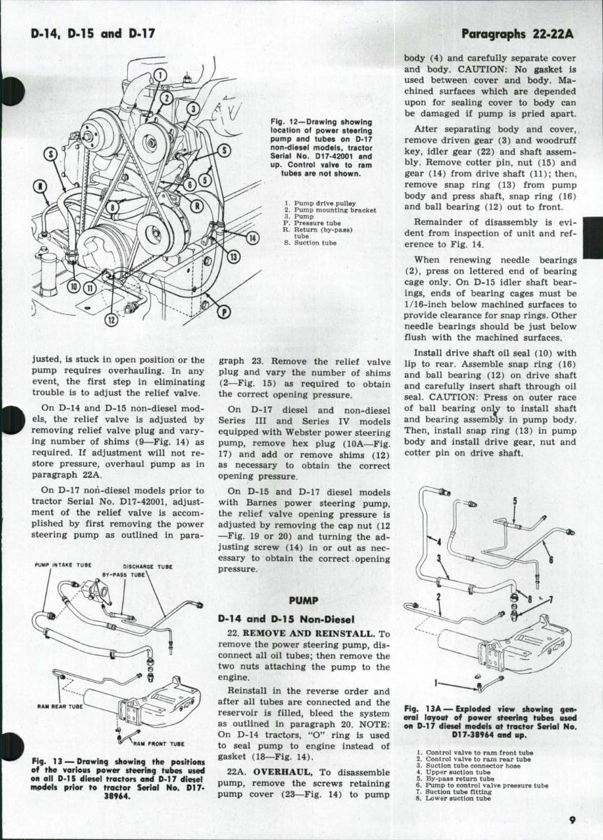
D-14. D.15 and D-17 Paragraphs 22-22A justed, is stuck in open position or the pump requires overhauling. In any event, the first step in eliminating trouble is to adjust the relief valve. On D-14 and D-15 non-diesel mod- els, the relief valve is adjusted by removing relief valve plug and vary- ing number of shims (9—Fig. 14) as required. If adjustment will not re- store pressure, overhaul pump as in paragraph 22A. On D-17 noii-diesel models prior to tractor Serial No. D17-42001, adjust- ment of the relief valve is accom- plished by first removing the power steering pump as outlined in para- PUMP INTAKE TUBE DtSCHARGE TUBE BY-PASS TUBE\ Fig. 12—Drawing showing iocatfon of power steering pump and tubes on D-17 non-diesel modeis, tractor Serial No. D17-42001 and up. Controi vaive to ram tubes are not shown. 1. Pump drtve pulley 2. Pump mounting bracket 3. Pump P. Pressure tube R. Return (by-pass) tube S. Suction tube RAM FRONT TUBE Fig. 13^Drawing showing the positions of the various power steering tubes used on aii D-15 diesel tractors and D-17 diesei models prior to tractor Seriai No. D17- 38964. graph 23. Remove the relief valve plug and vary the number of shims (2—Fig. 15) as required to obtain the correct opening pressure. On D-17 diesel and non-diesel Series III and Series IV models equipped with Webster power steering pump, remove hex plug (lOA—Fig. 17) and add or remove shims (12) as necessary to obtain the correct opening pressure. On D-15 and D-17 diesel models with Barnes power steering pump, the relief valve opening pressure is adjusted by removing the cap nut (12 —Fig. 19 or 20) and turning the ad- justing screw (14) in or out as nec- essary to obtain the correct - opening pressure. PUMP D-14 and D-15 Non-Diesel 22. REMOVE AND REINSTALL. To remove the power steering pump, dis- connect all oil tubes; then remove the two nuts attaching the pump to the engine. Reinstall in the reverse order and after all tubes are connected and the reservoir is filled, bleed the system as outlined in paragraph 20. NOTE: On D-14 tractors, "O" ring is used to seal pump to engine instead of gasket (18—Fig. 14). 22A. OVERHAUL, To disassemble pump, remove the screws retaining pump cover (23—Fig. 14) to pump body (4) and carefully separate cover and body. CAUTION: No gasket is used between cover and body. Ma- chined surfaces which are depended upon for sealing cover to body can be damaged if pump is pried apart. Alter separating body and cover, remove driven gear (3) and woodruff key, idler gear (22) and shaft assem- bly. Remove cotter pin, nut (15) and gear (14) from drive shaft (11); then, remove snap ring (13) from pump body and press shaft, snap ring (16) and ball bearing (12) out to front. Remainder of disassembly is evi- dent from inspection of unit and ref- erence to Fig. 14. When renewing needle bearings (2), press on lettered end of bearing cage only. On D-15 idler shaft bear- ings, ends of bearing cages must be 1/16-inch below machined surfaces to provide clearance for snap rings. Other needle bearings should be just below flush with the machined surfaces. Install drive shaft oil seal (10) with lip to rear. Assemble snap ring (16) and ball bearing (12) on drive shaft and carefully insert shaft through oil seal. CAUTION: Press on outer race of ball bearing only to install shaft and bearing assembly in pump body. Then, install snap ring (13) in pump body and install drive gear, nut and cotter pin on drive shaft. i Fig. 13A — Exploded view showing gen- eral iayout of power steering tubes used on D-17 diesel models at tractor Serial No. Dl 7-38964 and up. 1. Control valve to ram front tube 2. Control valve to ram rear tube 3. Suction tube connector hose 4. Upper suction tube 5. By-pass return tube 6. Pump to control valve pressure tube 7. Suction tube fitting 8. Lower suction tube
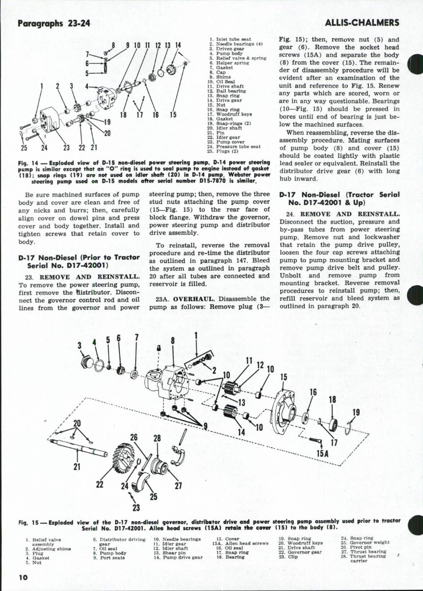
Paragraphs 23-24 ALLIS-CHALMERS 25 24 23 22 21 1. Inlet tube seat 2. Needle bearings (4) 3. Driven geax 4. Pump body 5. Relief valve & spring 6. Helper spring 7. Gaaket 8. Cap 9. Shims 10. Oil Seal 11. Drive shaft 12. Ball bearing ' 13. Snap ring 14. Drive gear 15. Nut 16. Snap ring 17. Woodruff keys 18. Gasket 19. Snap-rings (2) 20. Idler shaft 21. Pin 22. Idler gear 23. Pump cover 24. Pressure tube seat 25. Plugs (2) F{g. 14 — Expioded view of D-15 non-diesel power steering pump. D-14 power steering pump is simiior except that an "O" ring is used to seol pump to engine instead of gosket (18); snap rings (19) are not used on idier shaft (20) in D-14 pump. Webster power steering pump used on D-15 models after seriai number Dl 5-7870 is simiiar. Be sure machined surfaces of pump body and cover are clean and free of any nicks and burrs; then, carefully align cover on dowel pins and press cover and body together. Install and tighten screws that retain cover to body. D-17 Non-I>iesel (Prior to Tractor Serial No. Dl 7-42001) 23. REMOVE AND REINSTALL. To remove the power steering pump, first remove the fiistributor. Discon- nect the governor control rod and oil lines from the governor and power steering pump; then, remove the three stud nuts attaching the pump cover (15—Fig, 15) to the rear face of block flange. Withdraw the governor, power steering pump and distributor drive assembly. ^ To reinstall, reverse the removal procedure and re-time the distributor as outlined in paragraph 147. Bleed the system as outlined in paragraph 20 after all tubes are connected and reservoir is filled. 23A. OVERHAUL. Disassemble the pump as follows: Remove plug (3— Fig. 15); then, remove nut (5) and gear (6). Remove the socket head screws (15A) and separate the body (8) from the cover (15). The remain- der of disassembly procedure will be evident after an examination of the unit and reference to Fig. 15. Renew any parts which are scored, worn or are in any way questionable. Bearings (10—Fig. 15) should be pressed in bores until end of bearing is just be- low the machined surfaces. When reassembling, reverse the dis- assembly procedure. Mating surfaces of pump body (8) and cover (15) should be coated lightly with plastic lead sealer or equivalent. Reinstall the distributor drive gear (6) with long hub inward. D-17 Non-Diesei (Tractor Seriai No. Dl 7-42001 & Up) 24. REMOVE AND REINSTALL. Disconnect the suction, pressure and by-pass tubes from power steering pump. Remove nut and lock washer that retain the pump drive pulley, loosen the four cap screws attaching pump to pump mounting bracket and remove pump drive belt and pulley. Unbolt and remove pump from mounting bracket. Reverse removal procedures to reinstall pump; then, refill reservoir and bleed system as outlined in paragraph 20. Fig, 15 —Exploded view of the D-17 non-diesei governor, distributor drive and power steering pump assembly used prior to tractor Seriai No. Dl7-42001. Alieu head screws (15A) r«foin the cover (15) to the body (8). 1. Relief valve assembly 2. Adjusting shims 3. Plug 4. Gasket 5. Nut 6. Distributor driving gear 7. Oil seal 8. Pump body 9. Port seats 10. Needle bearings 11. Idler gear 12. Idler shaft 13. Shear pin 14. Pump drive gear 15. Cover 15A. Allen head screws 16. Oii seai 17. Snap ring 18. Bearing 19. Snap ring 20. Woodruff keys 21. Drive shaft 22. Governor gear 23. cup 24. Snap ring 25. Governor weight 26. Pivot pin 27. Thrust bearing 28. Thrust bearing -' carrier 10
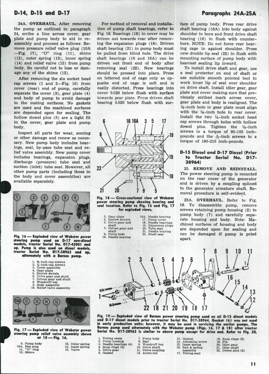
D-14, D-15 and D-17 Paragraphs 24A-25A 24A. OVERHAUL, After removing the pump as outlined in paragraph 24, scribe a line across cover, gear plate and pump body to aid in re- assembly and proceed as follows: Re- move pressure relief valve plug (lOA —Fig. 17), "O" ring (11), shims (12), outer spring (13), inner spring (14) and relief valve (15) from pump body. Be careful not to lose or dam- age any of the shims (12). After removing the six socket head cap screws (1 and 2—Fig. 16) from cover (rear) end of pump, carefully separate the cover (3), gear plate (4) and body of pump to avoid damage to the mating surfaces. No gaskets are used and the machined surfaces are depended upon for sealing. The hollow dowel pins (5) are a tight fit in the cover, gear plate and pump body. Inspect all parts for wear, scoring or other damage and renew as neces- sary. New pump body includes bear- ings, seal, by-pass tube seat and re- lief valve assembly. New pump cover includes bearings, expansion plugs, discharge (pressure) tube seat and suction (inlet) tube seat. However, all other pump parts (including those in the body and cover assemblies) are available separately. Fig. U — Exploded view of Webster power steering pump used on D-17 non-diesel models, tractor Seriai Ho. DI 7-42001 and up. Pump is also used on diesel models, tractor Seriai No. DI 7-38963 and up, olternatefy with a Barnes pump. 1. %-inch cap screws 2. 14-inch cap screws 3. Cover assembly 4. Gear plate 5. Hollow dowels 6. Drive gear and shaft 7. Driven gear and shaft 8. Woodruff key 9. Body assembly 10. Relief valve assenibly Fig. 17 — Exploded view of Webster power steering pump reiief vaive assembiy siiown at 10 —Fig. 16. 9. Pump body lOA. Hex plug 11. "O" ring 12. Shims For method of removal and installa- tion of pump shaft bearings, refer to Fig. 18. Bearings (18) in cover may be driven out towards rear after remov- ing the expansion plugs (19). Driven shaft bearing (21) in pump body must be pulled from blind hole. The drive shaft bearings (16 and 16A) can be driven out front end of body after removing seal (22). New bearings should be pressed into place. Press on lettered end of cage only as op- posite end of cage is soft and is easily distorted. Press bearings into cover 0.020 below flush with surface towards gear plate. Press driven shaft bearing 0.020 below flush with sur- 19 18 21 20 7 9 5 Fig. 18 — Cross-sectional view of Webster power steering pump showing bearing and seai location. Refer to Fig. 16 and Fig. 17 for expioded views. 3. Gear plate 5. Hollow dowela 6. Drive gear and Bhaft 7. Driven gear and shaft 9. Pump body 16. Needle bearing 16A. Needle bearing 17. Pump cover 18. Needle bearings 19. Expansion plugs 20. Tube seat 21. Needle bearing 22. Shaft seal face of pump body. Press rear drive shaft bearing (16A) into body against shoulder in bore and front drive shaft bearing (16) in flush with counter- bore. NOTE: Do not force rear bear- ing cage in against shoulder. Press new double lip seal (22) in flush with mounting surface of pump body with heaviest sealing lip inward. To install drive shaft and gear, use a seal protector on end of shaft or use suitable smooth pointed tool to work inner lip of seal over shoulder on drive shaft. Install idler gear, gear plate and cover making sure that pre- viously scribed mark across cover, gear plate and body is realigned. The ys-inch hole in gear plate must align with the Vs-inch hole in rear cover. Install the two y4-inch socket head cap screws through holes with hollow dowel pins. Tighten the V4-inch screws to a torque of 95-105 inch- pounds and the j^^-inch screws to a torque of 190-210 inch-pounds. 0-15 Diesel and D-17 Diesel (Prior to Tractor Serial No. D17- 38964} 25. REMOVE AND REINSTALL. The power steering pump is mounted on the rear cover of the generator and is driven by a coupling splined to the generator armature shaft. Re- moval procedure is self-evident. 25A. OVERHAUL. Refer to Fig. 19. To disassemble pump, remove screws retaining pump housing (2) to pump body (7) and carefully sepa- rate housing and body. Note: Ma- chined surfaces of housing and body are depended upon for sealing and can be damaged if pump is pried apart. 7 8 9 10 1.1 2 3 4 5 4 3 6 .—-c 22 18 21 20 19 18 17 Fig. 1 9 — Exploded view of Barnes power steering pump used on ail D-1S diesei modeis and D-17 diesel modeis prior to tractor Serial No. D17-38964. Goslcet (6) was not used in early production units; however, it may be used in servicing the earlier pumps. The Barnes pump used alternately with the Webster pump (Figs. 16, 17 & 18) after tractor Serial No. DI 7-28963 is simiiar to above pump except for drive end. Refer to Fig. 20, 13. Outer spring 14. Inner spring 15. Valve 1. Tubing seats 2. Pump housing 3. Needle bearings (4) 4. Snap rings (2) 5. Drive gear 6. Gasket 7. Pump body 8. Seal 9. Woodruff key 10. Drive shaft 11. Drive coupling 12. Acom nut 13. Gasket 14. Adjusting screw 15. Inner spring 16. Ball & spring assembly 17. Tubing stiat 18. Snap rings (2) 19. Pin 20. Idler gear 21. Idler shaft 22. Dowel pins (2) 11
This workshop service manual for the Allis Chalmers D15 series 2 Tractor is available for instant access, eliminating shipping costs and waiting time. The manual provides comprehensive data, instructions, and methodology for performing repair interventions on the vehicle and its components. It includes special notes, important points, service data, precautions, and detailed illustrations, exploded diagrams, drawings, and photos to guide through every service repair procedure.
The manual is designed for both professional mechanics and DIY enthusiasts, offering detailed, comprehensive step-by-step procedures, explanations, and pictorial diagrams from bumper to bumper. It covers adjustment and repair operations, including reference to service tool numbers and wear limits. The manual is printable and can be viewed on any computer, zoomed, and printed for convenience.
It provides general descriptions for accomplishing service and repair work with tested, effective techniques, ensuring reliability. The manual also includes information on construction, function, troubleshooting, servicing specifications, tightening torque, checking and adjusting, disassembling and assembling, and servicing procedures.
To maximize the life of the Allis Chalmers D15 series 2 Tractor, it is essential to follow the maintenance requirements, investigate unusual noises and changes in riding characteristics, use genuine parts, follow procedures carefully, keep complete records of all maintenance and repairs, and use approved lubricants as specified in the manual.
The manual is intended for use by trained technicians in a properly equipped workshop, but it contains enough detail and basic information to make it useful to owners who desire to perform their own basic maintenance and repair work. It also contains information about adjusting work and valuable reference data for adjustment values.
For all maintenance and repair work, accident prevention guidelines must be strictly observed, and a complete set of standard tools, as well as special tools and fixtures, are necessary. The manual outlines procedures for servicing and repairing vehicles using safe, effective methods, along with notes, cautions, and warnings to ensure safety.
It is a quality manual that is 100% complete and intact, with no missing or corrupt pages/sections. The manual is available in .PDF format and is suitable for both professional mechanics and DIY enthusiasts.
File Format: .PDF
Language: English
Printable: Yes
Requirement: Adobe Reader
Compatibility: Windows/ Mac and Linux OS
Recently Viewed
5,521,897Happy Clients
2,594,462eManuals
1,120,453Trusted Sellers
15Years in Business
Price:
Actual Price:
Allis Chalmers D15 series 2 Tractor Workshop Service Manual