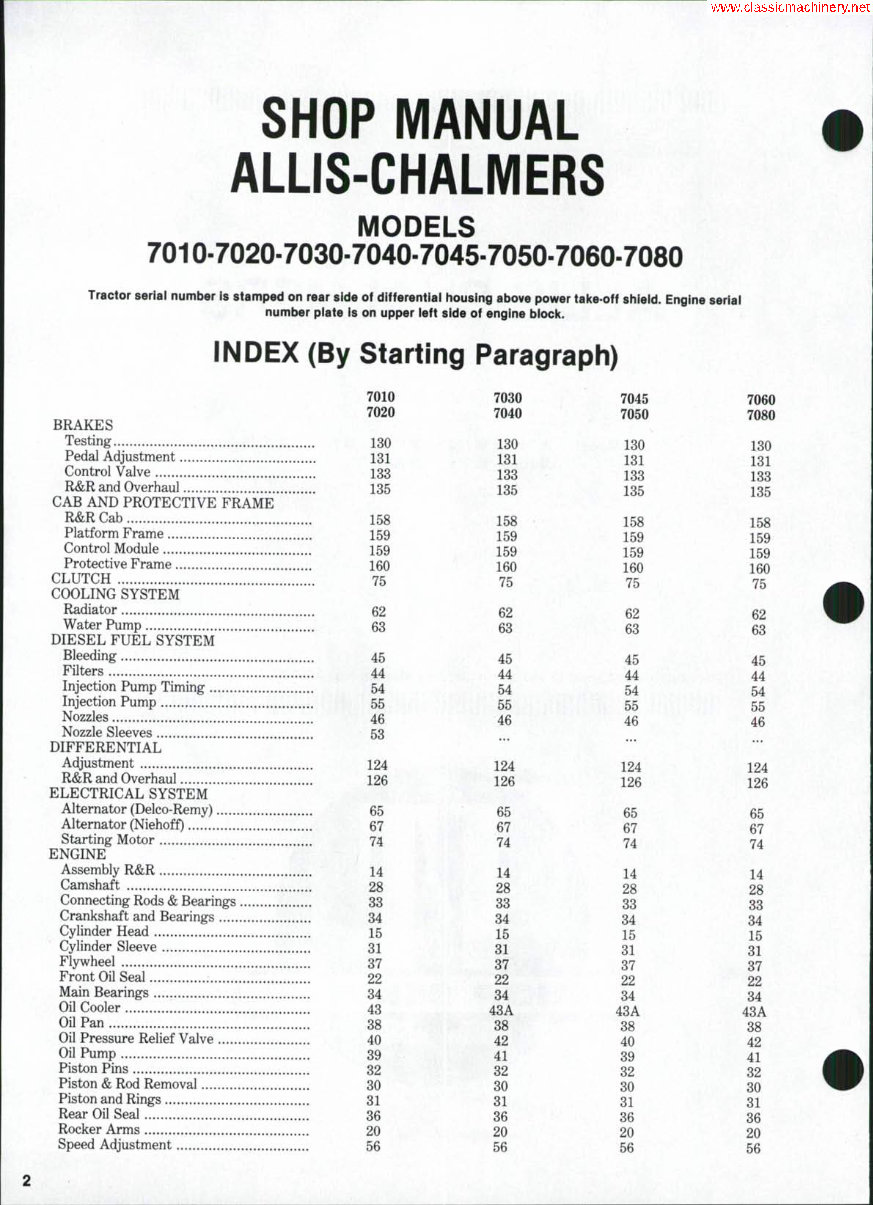
INDEX (Cont.) ENGINE CONT. Timing Gear Cover 22 22 22 22 Timing Gears..... 23 23 23 23 Valves & Seats 16 16 16 16 Valve Guides 17 17 17 17 Valve Lifters 19 19 19 19 Valve Springs 18 18 18 : . 18 Valve Timing 23 23 23 23^ Valve Clearance 21 21 21 21 FINAL GEAR Planetary 129 , 129 129 129 Remove and Reinstall 128 128 128 128 Wheel Axle Shaft 129 129 129 129 FRONT SYSTEM Axle Center Member 5 5 5 5 Axle Extensions 4 4 4 4 Tie Rods 3 3 3 3 Spindles 1 1 1 1 HYDRAULIC LIFT SYSTEM Test and Adjustments 143 143 143 143 High Pressure Checks 148 148 148 148 R&R Pumps 149 149 149 149 Piston Pump Overhaul 150 150 150 150 Gear & Gerotor Pump Overhaul 151 151 151 151 Scavenger Pump Overhaul ... 151A 151A 151A Control Valves 152 152 152 152 Remote Valve 153 153 153 153 Lift Housing & Cylinder 155 155 155 155 INTERCOOLER ... ... 61 61 "POWER-DIRECTOR" Tests and Adjustments 77 77 77 77 Clutch 86 86 86 86 Control Valve 85 85 85 85 Overhaul 87 87 87 87 POWER SHIFT Adjustment 93 93 93 93 Pressure Checks 101 101 101 101 Powershift Valve 106 106 106 106 R&R and Overhaul 114 114 114 114 POWER STEERING SYSTEM Cylinder 12 12 12 12 Control Valve 10 10 10 10 Lubrication & Bleeding 7 7 7 7 Operating Pressure 8 8 8 8 Troubleshooting 6 6 6 6 PTO Clutch Valve 154 154 154 154 Operating Pressure 136 136 136 136 R&R and Overhaul 137 137 137 137 TRANSMISSION (STANDARD) R&R and Overhaul 90 90 90 90 Shifter Assembly 91 91 91 91 TRANSMISSION (RANGE) R&R and Overhaul 121 121 121 121 TURBOCHARGER 57 57 57 57 DUAL DIMENSIONS This service manual provides specifications in both the U.S. Customary and Metric (SI) systems of measurement. The first specification is given in the measuring system perceived by us to be the preferred system when servicing a particular component, while the second specification (given in parenthesis) is the converted measurement. For instance, a specification of "0.011 inch (0.28 mm)" would indicate that we feel the preferred measurement, in this instance, is the U.S. system of measurement and the metric equivalent of 0.011 inch is 0.28 mm.
CONDENSED SERVICE DATA Models 7010-7020-7030-7040 7010 GENERAL Engine Make Own Engine Model 649T Number of Cylinders 6 Bore 3.875 in. (98.43 mm) Stroke 4.250 in. (107.95 mm) Displacement 301 cu. in. (4909 cc) Main Bearings, Number of 7 Cylinder Sleeves Wet Alternator & Starter Make DELCO-REMY* *Some models are equipped with Niehoff. 7020 7030 7040 Own 6491 6 3.875 in. (98.43 mm) 4.250 in. (107.95 mm) 301 cu. in. (4909 cc) 7 Wet DELCO-REMY* Own 3500 MARK II 6 4.250 in. (107.95 mm) 5.000 in. (127.0 mm) 426 cu. in. (6982 cc) 7 Wet DELCO-REMY* Own 3500 MARK II 6 4.250 in. (107.95 mm) 5.000 in. (127.0 mm) 426 cu. in. (6982 cc) 7 Wet DELCO-REMY* TUNE-UP Firing Order 1-5-3-6-2-4 Valve Tappet Gap (Hot) Intake & Exhaust 0.015 in. (0.38 mm) Valve Seat Angle Inlet & Exhaust 30° Injection Timing 18°BTDC Injection Pump Make Timing Mark Location Battery Terminal, Ground NEG. Engine Low Idle Rpm 750-800 Engine High Idle Rpm, No Load 2480-2580 Engine Full Load Rpm 2300 StZES-CAPACITIES-CLEARANCES Crankshaft Main Journal Diameter 2.7465-2.7480 in. - (69.761-69.799 mm) Crankpin Diameter 2.3720-2.3735 in. - (60.248-60.286 mm) Camshaft Journal Diameter, All 2.130-2.131 in.— (54.10-54.13 mm) Piston Pin Diameter 1.2515-1.2517 in. - (31.78-31.79 mm) Valve Stem Diameter, Inlet 0.3715-0.3720 in. - (9.436-9.448 mm) Exhaust 0.3705-0.3710 in. - (9.410-9.423 mm) Main Bearing Diametral Clearance 0.0016-0.0048 in. - (0,04-0.12 mm) Rod Bearing Diametral Clearance 0.0009-0.0039 in. - (0.02-0.10 mm) Piston Skirt Diametral Clearance 0.0045-0.0070 in. - (0.11-0.18 mm) Crankshaft End Play 0.004-0.010 in.— (0.10-0.25 mm) Camshaft Bearings Diametral Clearance 0,002-0.005 in.— (0.05-0.13 mm) 1-5-3-6-2-4 0.015 in. (0.38 mm) 1-5-3-6-2-4 0.015 in. (0.38 mm) 30° 30° 18°BTDC 24°BTDC ROOSA-MASTER - CRANKSHAFT PULLEY - NEG. 750-800 2480-2580 2300 NEG. 700-750 2500-2550 2300 1-5-3-6-2-4 0.015 in. (0.38 mm) 30° 16°BTDC NEG, 700-750 2500-2645 2300 3,2465-3.248 in. (82.461-82.499 mm) - 2,7470-2.7485 in. - (69.773-69,811 mm) —2.130-2.131 in.— (54.10-54,13 mm) - 1.5011-1,5013 in. - (38.127-38.133 mm) - 0.3715-0.3720 in, - (9.436-9,448 mm) - 0.3705-0.3710 in. - (9,410-9.423 mm) 0.0019-0.0051 in. (0.048-0.129 mm) -0,001-0.004 in.- (0.02-0.10 mm) 0.0025-0.0050 in, (0.063-0.127 mm) —0,007-0.013 in.— (0.18-0.33 mm) -0.002-0,006 in.- (0,050-0.15 mm)
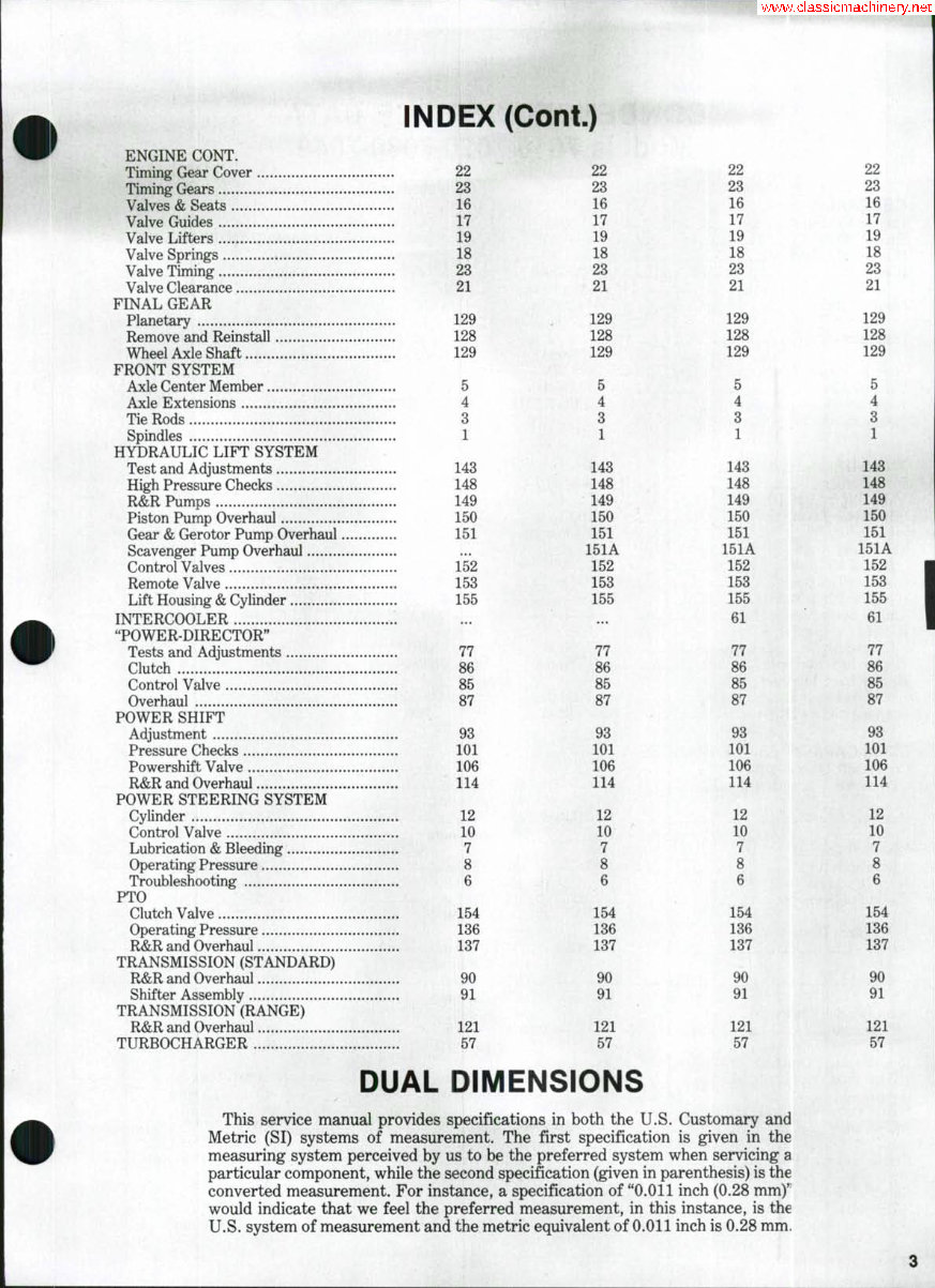
CONDENSED SERVICE DATA (Cont.) 7010 SIZES-CAPACITIES-CLEARANCES (Cont.) Camshaft End Play Cooling System Capacity* 26 qts. (24.5 L) Crankcase Oil* 16 qts. (15.1 L) Transmission* 7.4 gal. (28.0 L) Differential* 16.7 gal. (63.46 L) *Approximate capacity TIGHTENING TORQUES Greneral Recommendations Rod Bearing Cap Screws Cylinder Head Cap Screws Fljrwheel Cap Screws Injection Nozzle Nuts Main Bearing Screws 7020 7030 7040 -0.001-O.Ollin. (0.03-0.28 mm) 26 qts. (24.5 L) 16 qts. (15.1 L) 7.4 gal. (28.0 L) 16.7 gal. (63.46 L) -0.0027-0.0083 in.- (0.068-0.210 mm) 32. qts. 32 qts. (30.2 L) (30.2 L) 19 qts. 19 qts, (17.9 L) (17.9 L) 7.4 gal. 7.4 gal. (28.0 L) (28.0 L) 16.7 gal. 16.7 gal. (63.46 L) (63.46 L) —165.ft.-lbs.- (224.0 N*m) See End of Shop Manual See Paragraph 30— —150 ft.-lbs.- (203.2 N*m) -135 ft.-lbs. (182.9 -40-60 ft.-lbs. (54.2-81.3 N»m)- 135 ft.-lbs.- (183.0 N*m) -170-19C ft.-lbs.— (230.3-257.4 N»m) Models 7045-7050-7060-7080 7045 GENERAL Engine Make Own Engine Model 670T Number of Cylinders 6 Bore 4.250 in. (107.95 mm) Stroke 5.000 in. (127.0 mm) Displacement 426 cu. in. (6982 cc) Main Bearings, Number of 7 Cylinder Sleeves Wet Alternator & Starter Make DELCO-REMY* *Some models are equipped with Niehoff. TUNE-UP Firing Order 1-5-3-6-2-4 Valve Tappet Gap (Hot) Intake & Exhaust 0.015 in. (0.38 mm) Valve Seat Angle Inlet & Exhaust 30° Injection Timing 16°BTDC Injection Pump Make Timing Mark Location Battery Terminal, Ground NEG. Engine Low Idle Rpm 700-750 Engine High Idle Rpm, No Load 2500-2550 Engine Full Load Rpm 2300 SIZES-CAPACITIES-CLEARANCES Crankshaft Main Journal Diameter Crankpin Diameter Camshaft Journal Diameter, All 7050 7060 7080 Own 3700 6 4.250 in. (107.95 mm) 5.000 in. (127.0 mm) 426 cu. in. (6982 cc) 7 Wet DELCO-REMY* 1-5-3-6-2-4 0.015 in. (0.38 mm) Own 3700 6 4.250 in. (107.95 mm) 5.000 in. (127.0 mm) 426 cu. in. (6982 cc) 7 Wet DELCO-REMY* 1-5-3-6-2-4 0.015 in. (0.38 mm) Own 3750 MARK II 6 4.250 in. (107.95 mm) 5.000 in. (127.0 mm) 426 cu. in (6982 cc) 7 Wet DELCO-REMY 1-5-3-6-2-4 0.015 in. (0.38 mm) 30° 30° 26°BTDC 18°BTDC ROOSA-MASTER ~ CRANKSHAFT PULLEY - NEG. NEG. 700-750 700-750 30° 22°BTDC 2500-2550 2300 2500-2645 2300 NEG. 725-775 2800-2850 2550 3.2465-3.248 in. (82.461-82.499 mm) 2.7470-2.7485 in. (69.773-69.811 mm) 2.130-2.131 in. (54.10-54.13 mm)
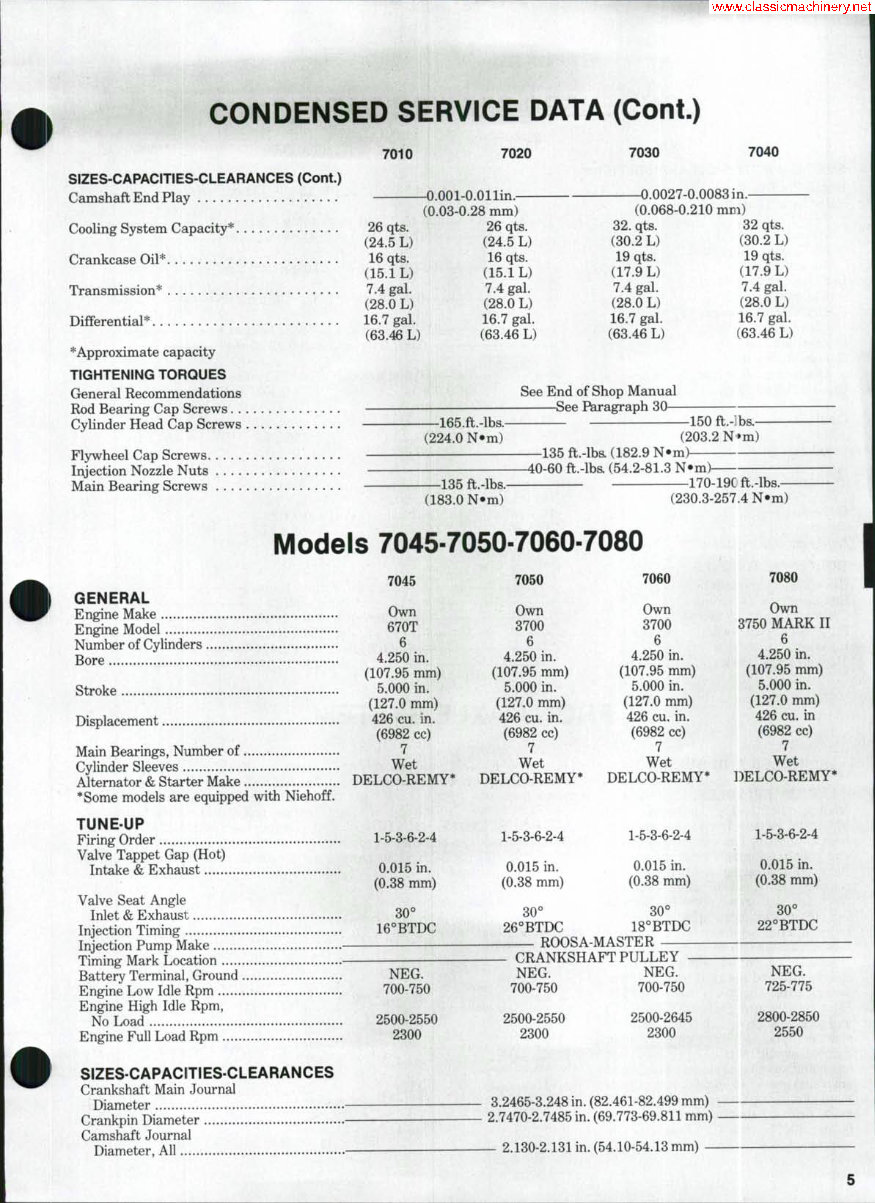
CONDENSED SERVICE DATA (Cont.) 7045 SIZES-CAPACITIES-CLEARANCES (Cont.) Piston Pin Diameter Valve Stem Diameter Inlet Exhaust Main Bearing Diametral Clearance Rod Bearing Diametral Clearance Piston Skirt Diametral Clearance Crankshaft End Play Camshaft Bearings Diametral Clearance Camshaft End Play 0.001-0. (O.O2-O.20 Cooling System Capacity* 32 qts. (30.2 L) Crankcase Oil* 19 qts. (17.9 L) Transmission* 7.4 gal. (28.0 L) Differential* 16.7 gal. (63.46 L) *Approximate capacity : TIGHTENING TORQUES General Recommendations Rod Bearing Cap Screws Cylinder Head Cap Screws Flywheel Cap Screws Injection Nozzle Nuts Main Bearing Screws 7050 7060 7080 1.5011-1.5013 in.(38.127-38.133 mm)- 0.3715-0.3720 in. (9.436-9.448 mm)- 0.3705-0,3710 in (9,410-9.423 mm)- 0.0019-0.0051 in. (0.048-0.129 mm)- -0,001-0.004 in(0.02-0.10 mm)- 0,0025-0.0050 in, (0.063-0.127 mm)- —0.007-0,013 in. (0,18-0.33 m m ) — -0.002-0.006 in.(0.05-0.15 mm)- )08 m. mm) 32 qts. (30.2 L) 19 qts. (17.9 L) 7,4 gal. (28.0 L) 16.7 gal. (63.46 L) 0.0027-0.0083 in. (0.068-0.21( 32 qts. (30.2 L) 19 qts. (17,9 L) 7.4 gal. (28.0 L) 16.7 gal. (63.46 L) ) mm) 36 qts. (34.1 L) 19 qts. (17.9 L) 7.4 gal. (28.0 L) 17.1 gal. (64.98 L) -See End of Shop Manual- See Paragraph 30 -150 ft.-lb& (203.2 N< -135 ft.-lhs. (182.9 N^ m)- m)- —40-60 ft,-lb& (54.2-81.3 N»m) -170-190 ft.-lbs. (230,3-257.4 N*m)- FRONT AXLE SYSTEM SPINDLES AND BUSHINGS 1, R&R SPINDLES. To remove front spindle (15-Fig. 1), support front of tractor, remove front wheel and pro- ceed as follows: Remove snap ring (10) and pull steering arm (9) from spindle. Removal of steering arm will probably cequire it to be cut off using a suitable torch due to extreme press fit. Remove key (12) and withdraw spindle from bot- tom of axle extension (11). Remove thrust washers (16) from spindle. Install two thrust washers (16) on spindle (15) and install it in axle exten- sion (11) from bottom. Install key (12). Heat steering arm (9) to 600^F (315°C) and press it on spindle so maximum shaft end play is 0,030 inch (0.76 mm). Spindle should rotate freely between stops and steering arm must be clear of snap ring groove in spindle. Any adjust- ment of steering arm on spindle must be made prior to steering arm cooling to below 300°F (148°C). Reseating or removal of steering arm after it has cool- ed below 300°F (148'^'C) will probably re- quire it to be cut off with a torch due to extreme press fit, 2. R&R SPINDLE BUSHINGS. Spindle bushings can be renewed after removing spindle as outlined in para- Flg, I-'Exploded view of adlustable front axle assembly, 1. Seal 2. Wear sleeve 3. Bearing assy, (inner) 4. Hub 5. Bearing assy, (outer) 6. Washer 7. Nut 8. Cap 9. Arm 10. Snap ring 11. Axle extension 12. Key 13. Bushing (upper) 14. Bushing (lower) 15. Spindle 16. TTirust washers 17. Washers 18. Pivot pin 19. Axle main member graph 1. Remove bushings (13 and 14-Fig. 1) using a suitable bushing driver or drift punch. New bushings are presized and should not require reaming if carefully installed. Install upper and lower bushings in axle extension (11), us- ing a suitable press or shoulder punch, 10 9 15 16 19 6
SHOP MANUAL Paragraphs 3-5 until they are flush to 0.030 inch (0.76 mm) below end of bore. Reinstall spindle as outlined in paragraph 1. TIE RODS AND TOE-IN 3. Toe-in of front wheels should be 3/32 to 7/16 inch (2.4 to 11.1 mm) measured from OD of tire at spindle height. To adjust toe-in remove nut (6-Fig. 2) and disconnect tie rod end (1) from spindle. Loosen jam nut (2) and turn tie rod end in or out as necessary to correct toe-in. Fig. 2^Expioded ¥lew of tie rod and components. Refer to text 1. Tie rod end 2. Locknut 3. Tube 4. Tie rod end 5. Arm 6. Nuts 7. Seal 8. Seal AXLE EXTENSIONS 4. To renew axle extension (11-Fig. 1), remove spindle as outlined in para- graph 1, then remove tread width ad- justing bolts and withdraw axle exten- sion from main member (19). AXLE CENTER (MAIN)MEMBER AND PIVOT PIN 5. The axle center (main) member is a welded one-piece assembly (19-Fig. 1). The center member pivots on one long pin. The pin pivots in renewable bushings in front support casting. To renew the pivot pin, proceed as follows: Support tractor under torque housing so that no weight is carried on front axle. Then, remove the retaining bolt and drive out pivc»t pin. Then, raise front of tractor until front support is clear of axle and drive bushings out of front support casting with suitable driver. New bushings are presized and should not require reaming if carefully installed. Install pivot pin (18) with one thrust washer (17) at rear. Install enough thrust washers (17) at front to establish an end play of 0.00-0.17 inch (0.0-4.3 mm). To renew axle center (main) member, remove both axle extensions as outlined in paragraph 4, discornect power steer- ing cylinder at both 3nds and remove front axle pivot pin. POWER STEERING SYSTEM All models are equipped with hydro- static power steering system that has no mechanical linkage between steering wheel and front steering cylinder. Refer to Fig. 3 for drawing showing the steer- ing system. There are three pumps located together under the range transmission. Pumps are driven by a shaft from the pto gear train. Pumps are bolted together in one housing but are of dif- ferent type and supply oil te three separate circuits. A brief description of the pumps from front to rear follows. Refer to Fig. 4. Front pump is an axial piston pump which delivers oil to the following: 1. 3-point hitch. 2. Remote control valve. 3. Power take-off valve. 4. Differential lock valve. 5. Brakes control valve. Middle pump is a gear type with a flow divider. Flow divider splits output into priority and secondary flow and supplies oil for the following functions: A. Priority flow: 1. Power steering. 2. Cooling oil in rear axle. 3. Filtering oil in rear axle. B. Secondary flow: 1. Lubricating and cooling oil for brakes. 2. Lubricating and cooling oil for pto cluteh. Rear pump is a gerotor type and is recessed into range transmission hous- ing. It is the only pump that is not visible from the outside of tracter. This pump supplies oil te the following: 1. Power directer cluteh or power shift cluteh. 2. Power director or power shift clutehes, lubrication and cooling. 3. Lubrication, cooling and filtering of standard and range transmissions. The control valve unit (8-Fig. 3) con- tains a rotary metering motor, a com- mutator feed valve sleeve and a selecter valve spool. In event of engine or hydraulic power failure, the metering motor becomes a rotary hand pump to actuate the power steering cylinder when steering wheel LS turned. A check valve within the gear pump housing allows recirculation (f fluid within the control valve and steoring cylinder dur- ing manual operation NOTE: The malnteniince and absolute cleanliness of all parts Is of utmost Impor- tance In the operation iind servicing of the hydraulic power steertr g system. Of equal Importance is the avoidance of nicks or burns on any of the working parts. Do not use cioth shop towels in cieaning internal parts; use only lint-freo shop toweis. Fig. 3-A schematic show- ing components of hydrauiic power steering system. No mechanicai linkage is used between steering wheei and tractor front wheels. 1. Filters 2. Tube (intake) 3. Pump 4. Tube (return) 5. Tube (to inlet hose) 6. Hose (outlet) 7. Hose (inlet) 8. Steering control valve 9. Tube 10. Hose 11. Oil cooler 12. Hose 13. Tube 14. Steering cylinder 15. Hose (valve to cylinder) 16. Hose (valve to cylinder)
Paragraphs 6-8 ALLIS-CHALMERS TROUBLESHOOTING 6. Before attempting to adjust or repair the power steering system, the cause of any malfunction should be located. Refer to the following para- graphs for possible causes of power steering system malfunction: Irregular or "Sticky" Steering. If ir- regular or "sticky" feeling is noted when turning steering wheel with forward' motion of tractor stopped and with engine running at rated speed, or if steering wheel continues to rotate after being turned and released, foreign material in the power steering fluid (transmission oil) is probable cause. Clean or renew all hydraulic system filters. It will be necessary to also drain transmission oil and refill with clean oil. Also check for air leaks in gear pump suction line which will cause pump to cavitate. If trouble is not corrected, the power steering control valve assembly should be removed and serviced; refer to paragraph 10. Steering Cylinder ''Hesitates*'. If steering cylinder appears to pause in travel when steering wheel is being turned steadily, probable cause of trou- ble is air trapped in the power steering cylinder. Bleed cylinder as outlined in paragraph 7. Slow Steering. Slow steering may be caused by low oil flow from pump. Check time required for full stroke travel of power steering cylinder; first, with trac- tor weight on the front wheels; then, with front end of tractor supported by a jack. If time between the two checks varies considerably, overhaul power steering pump as outlined in paragraph 151. Loss of Power. Loss of steering power may be caused by system relief setting being too low. Check and adjust relief valve setting as outlined in paragraph 11. Left, rear fluid filter (9 - Fig. 5) plugg- ed or wrong size. Filter shoiid be 6.10-6.16 inches (154.9456.4 mm) long. Orifice disc (8-Fig. 6) in gear pump flow divider plugged. Remove spool (4) 10 11 12 10 13 Fig, S — Fliter on ieft side of rear housing is fiiter for gear pump. 1. Seal 2. Check valve 3. Head 4. Seal 5. Housing 6. Spring 7. Bar 8. Valve 9. Filter 10. "0" rings 11. Cap 12. Strap 13. Cover from gear pump and clean orifice plate. Relief valve (8 - Fig. 9) in steering con- trol valve stuck open. Steering control valve assembly should be removed and serviced; refer to paragraph 10. System Overheats. Overheating of system may be caused by neutral (by- pass) pressure being too high. If neutral pressure is excessive, check for obstruc- tions in system such as kinked tube, etc. If neutral pressure is erratic, check for binding of control valve shaft, spool and/or sleeve. Too much oil in rear housing sump. Shut off engine and allow tractor to stand for 10 minutes, check oil level through sight glass in rear housing. Drain as necessary. LUBRICATION AND BLEEDING 7. Differential and final drive oil is utilized as the power steering fiuid. The filter, shown in Fig. 5 is located in lower front part of differential housing on left- hand side. This filter is for the gear pump which supplies the power steer- ing, and should be renewed after the first 50 hours and thereafter not to ex- ceed over 1000 hours. The power steer- ing system is usually self-bleeding. With engine running at high idle speed, cycle system through several full strokes of the cylinder. In some cases, it may be necessary to loosen connections at cylinder to bleed trapped air. COMPthlSATOR Fig. $-Expioded view of fiow divider. 1. Plug 2. "0" ring 3. End cap 4. Spool 5. Gear pump housing 6. Test port plug 7. "0" ring 8. Orifice disc 9. Spring 10. Shims 11. End cap 12. "C'ring 13. Plug SYSTEM OPERATING PRESSURE AND RELIEF VALVE 8. Power steering relief pressure can be checked by connecting a Flo-Rater in- to test port of gear pump. Refer to Fig. 4 showing test port location and to Fig. 7 showing Flo-Rater connected. Connect review of the three hydraulic pumps used. Test port (T) is used for diagnosis of gear pump hydraulic system. Fig. 7- View of hydrauiic tester connected for testing power steering system. Refer to text. 8
SHOP MANUAL Paragraphs 9-11 outlet from Flo-Rater to remote outlet on tractor. MAKE SURE REMOTE VALVE LEVER FOR OUTLET THAT IS CONNECTED TO FLO-RATER IS IN FLOAT POSITION. This is to assure sufficient oil to charge the piston pump. Start engine and operate at 1500 rpm. Turn steering wheel to one end of its travel and hold in that position. Turn restrictor valve on Flo-Rater until 1000-1500 psi (6.810.3 MPa) reading is obtained. Operate in this manner until fluid reaches a temperature of 130°-140°F (54.4°-60.0°C). After temperature has been reached, increase engine speed to 2300 rpm and check flow at 1000 psi (6.96 MPa) with steer- ing wheel held at end of travel. Flow should be 5.25 to 5.75 gpm (19.8-21,7 L/min.). Then, reduce engine speed to 1100 rpm at which point flow should not be less than 3.0 gpm (11.3 L/min.) for Model 7010, 7020 and 7045 tractors, or 3.5-4.5 gpm (13.2-17.0 L/min.) for all other models. Set engine speed at 2300 rpm and close restrictor valve to check steering relief valve pressure. This pressure should be 1800-2000 psi (12.4-15.88 MPa) at 2300 rpm. If relief valve pressure is found to be incorrect, the upper end of orbitrol motor will have to be removed to adjust the relief valve. If flow is not as stated, flow divider could be defective or pump may be worn and not producing enough volume. To check pump volume proceed as follows: Remove flow divider cap (3-Fig. 6), spool (4), orifice disc (8) and spring (9). Disconnect priority line to steering valve and plug fitting at flow divider. Disconnect secondary line to dif- ferential lock valve and plug fitting at fiow divider. CAUTION: Make sure restrictor valve on flow-tester is in open position as there is no relief valve protection. 10 11 "R"PORT IConnecl to Rwl endofCyl.) *1N" PORT toFump Line) _ *OUT" PORT (Connect it> F , , ^ Return Un«) I Fig. 8 — View of steering controi valve showing port iocations. Pressure tube from pump con- nects to **IN" port; return tube to sump connects to "OUT* port; tube to rear end of cylinder con- nects to "L" (ieft turn} port; and tube to rod end of cyiinder connects to "ff" (right turn) port. 13 15 16 17 18 19 20 21 22 23 Fig. 9—Exploded view of steering controi assembiy. Centering springs (14) are instaiied in two groups of three springs with arch in each group back-tO'ba'7k. 1. Oil seal 2. Mounting plate 3. Quad ring 4. "0" ring 5. Locator 6. Bearing races 7. Thrust bearing 8. Relief valve plug 9. Spring 10. Guide 11. Spool 12. Control valve body 13. Centering pin 14. Centering springs (6) 15. Sleeve 16. Valve spool 17. Plate 18. Drive shaft 19. Spacer 20. Rotor 21. Ring 22. Cover (cap) 23. Cap screw Start engine, run at 2300 rpm and ad- just restrictor on Flo-Rater until there is a pressure reading of 2000 psi (13.79 MPa). At this time, fiow should be 9 gpm (34.0 L/min.) minimum. If correct pressure and flow are found, but there is still difficulty with the steering, steer- ing valve or steering cylinder could be the trouble. Before removing steering valve, check steering cylinder as follows: Remove both hoses from cylinder and connect cylinder hoses together. At- tempt to rotate steering wheel. If steer- ing wheel will not rotate, steering valve is okay and trouble is in steering cylinder. If steering wheel will rotate, trouble is in steering valve. POWER STEERING PUMP 9. The gear type pump is the center of three pumps under the range transmis- sion where they are driven by a shaft from pto gear train. For service information on all three pumps refer to paragraph 149. CONTROL VALVE 10. REMOVE AND REINSTALL. Remove hood and disconnect the four hoses from control valve. Unbolt and remove control valve assembly from steering shaft housing. Reinstall control valve by reversing removal procedure. Refer to Fig. 8 for proper hose locations. Install new "0" ring seals on hose fittings before connec- ting hoses to control valve and tighten fittings securely. Bleed trapped air from power steering cylinder as outlined in paragraph 7 after assembly is com- pleted. 11. OVERHAUL CONTROL VALVE. After removing control valve as outlined in paragraDh 10, proceed as follows: Clean valve thoroughly and remove paint from po nts of separation with a wire brush. NOTE: A clean work bench is necessary. Also, use only lint-free paper shop towels for cleaning valve parts. If oil leakage past s;eal (1-Fig. 9) is the only difficulty, a new seal can be in- stalled after removing mounting plate (2). Install new quad ring (3) and "0" ring (4) in mounting plate; then reinstall mounting plate and tighten retaining cap screws equally to a torque of 21 ft-lbs. (28.35 N-m). To completely disassemble and over- haul, refer to exploded view in Fig. 9 and proceed as follows: Clamp valve mounting plate in vise with cap end up. Remove retaining cap screws (23). Remove end cap (22), gerotor set (20 and 21), plate (17) and dri\e shaft (18) from valve body as a unit. Remove valve from vise, place a clean wood block in vise throat and set valve assembly on block with mounting plate (^:) end up. Lightly clamp vise against port face of valve body and remove mounting plate retain- ing screws. Hold spoc'l assembly down against wood block while removing mounting plate. Remove valve body from vise and place on work bench with port face down. Caref illy remove spool and sleeve assembly (15 and 16) from 14-hole end of valve body. Using a screwdriver, remove relief valve plug (8) from housing; then, renove spool, guide and spring. Remove centering p n (13) from spool and sleeve assembly, hold sleeve and 9
Paragraphs 12-14 ALLIS-CHALMERS 1 2 3 4 5 6 7 9 10 11 12 13 push spool, (splined end first) out of sleeve. Remove the six centering springs (14) from slot in spool. Separate end cap and plate from gerotor set and remove drive shaft, rotor and spacer. Inspect all moving parts for scoring. Slightly scored parts can be cleaned by hand, rubbing with 400 grit abrasive paper. To recondition gerotor section surfaces, place a sheet of 600 grit paper on plate glass, lapping plate or other ab- solutely flat surface and remove sharp particles from paper with a fiat piece of scrap steel. Stroke each surface of the gerotor section over the abrasive paper; any small bright areas indicate burrs that must be removed. Polish each part, rinse in clean solvent and air dry; keep these parts absolutely clean for reassembly. Renew all parts that are excessively worn, scored or otherwise damaged. In- stall new seal kit when reassembling. To reassemble valve, proceed as follows: Install relief valve guide on spool and install in relief valve hole. Then, install spring and plug with new "0" ring. Turn plug in until it is at least flush with housing surface. The exact relief valve setting should be checked on a test stand after valve is assembled. Lubricate valve spool and carefully in- sert spool in valve sleeve using a twisting motion. Be sure that spring slots in spool and sleeve are at same end of assembly. Stand assembly on end with spring slots up and aligned. Assem- ble the springs in two groups with ex- Fig. 10-Exploded view of power steering cylinder. 1. Swivel 2. Cylinder rod 3. Snap ring 4. Retainer 5. Wiper 6. Seal 7. Head 8. Back-up ring 9. "0" ring 10. Piston 11. Piston seal 12. "0" ring 13. Locknut 14. Cylinder tended edges of springs down. Place the two groups of springs back-to-back (ar- ched sections together) and install spr- ings into spring slot in sleeve and spool in this position. Use a small screwdriver to guide springs through slots in op- posite side of assembly. Center springs in sleeve with edges flush with upper surface of sleeve. Insert centering pin (13) through spool and sleeve assembly so that both ends of pin are below fiush with outside of sleeve (15). On some models, nylon plugs are located at ends of centering pin to prevent pin from con- tacting inside diameter of valve body. Carefully insert spool and sleeve assembly, splined end first, in 14-hole end of valve body (12). Set valve body on clean surface with 14-hole end down. Install locator bushing (5) in valve bore with chamfered side up. Install thrust bearing assembly (6 and 7) over valve spool (16). Install new quad ring (3) and "0" ring (4) in mounting plate; lubricate seal and install mounting plate over valve spool and locator bushing. Tighten mounting plate retaining screws evenly to a torque of 21 ft.-lbs. (28.35 N-m). Clamp mounting plate in a vise with 14-hole end of valve body up. Place plate (17) and gerotor outer ring (21) on valve body so bolt holes align. Insert drive shaft (18) in gerotor inner rotor so slot in shaft is aligned with valleys in rotor and push shaft through rotor so that about V2 of the splines protrude. Holding shaft and rotor in this position, insert them in valve housing so notch in shaft engages centering pin in valve sleeve and spool. Install spacer (19) at end of drive shaft. If spacer does not drop down flush with rotor, shaft is not properly engaged with centering pin. Install end cap and tighten retaining screws equally to a tor- que of 20 ft.-lbs. (27.0 N-m). If a source of hydraulic power for testing is available, relief valve may be checked as follows: Refer to Fig. 8 and plug "R" and "L" ports. Connect a pressure gage in pressure line from pump and to "IN" port. Connect a line from "OUT" port to sump. Support valve in a vise and turn shaft until relief valve opens. Relief valve should open at 1750-1800 psi (11.44-12.43 MPa). If relief pressure is incorrect, remove end plate (2-Fig. 9) and adjust relief valve until correct reading is obtained. If no bench testing is available then adjust as outlined in paragraph 8. POWER STEERING CYLINDER 12. R&R AND OVERHAUL. Thor- oughly clean cylinder and hose fitting to avoid entry of dirt when lines are dis- connected. After hoses are disconnected remove bolts at each end of cylinder and remove cylinder. Work cylinder piston each way to end of stroke to expel oil from cylinder. 13. With cylinder removed as outlined in paragraph 12, refer to Fig. 10 and proceed as follows: Remove retaining ring (3); then push head toward piston end of cylinder and remove snap ring (4). Slide rod, piston and head out of cylinder tube. Remove nut (13), piston (10) and head (7) from rod. Inspect inside of cylinder tube and rod assembly for excess scratching, scoring or pitting. Inspect seals for nicks and cuts. Reassembly is reverse of disassembly, making sure that back-up washer (8) goes to rod end of cylinder and head (7) is installed with tapered end toward piston end of rod. Torque locking nut (13) to 220-250 ft.-lbs. (297-337.5 N-m). ENGINE AND COMPONENTS Model 7010 tractor uses the 649T engine while Model 7020 tractor uses the 6491 engine. Both engines are turbo- charged with the 6491 engine also being intercooled. Models 7030 and 7040 use the 3700 engine with turbocharger and inter- cooler. Model 7045 tractors use the turbo- charged 670T engine. Models 7050 and 7060 use the 3700 engine with turbocharger and inter- cooler. Model 7080 tractor is equipped with the 3750 engine with turbocharger, in- tercooling and counterbalanced crank- shaft. R&R ENGINE ASSEMBLY 14. Removal of engine is best ac- complished by removing radiator, front support, front axle and wheels assem- bly. Then, unbolt and remove engine and side rails from transmission housing as follows: Drain cooling system, disconnect bat- tery cables and remove right and left hood assemblies. Remove panel at front of console, and remove the top hood assembly. Disconnect radiator hoses and air cleaner inlet hose. Identify and dis- connect power steering lines, power 10
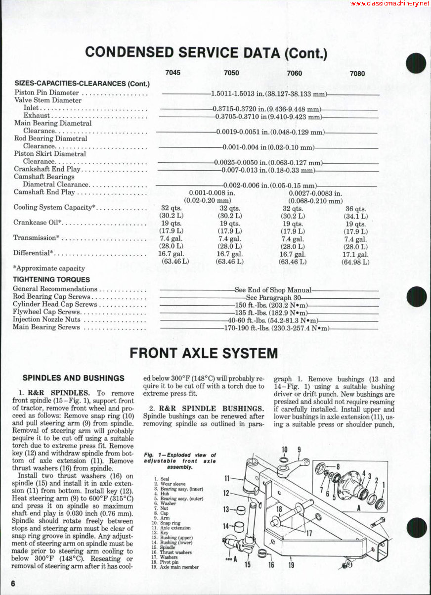
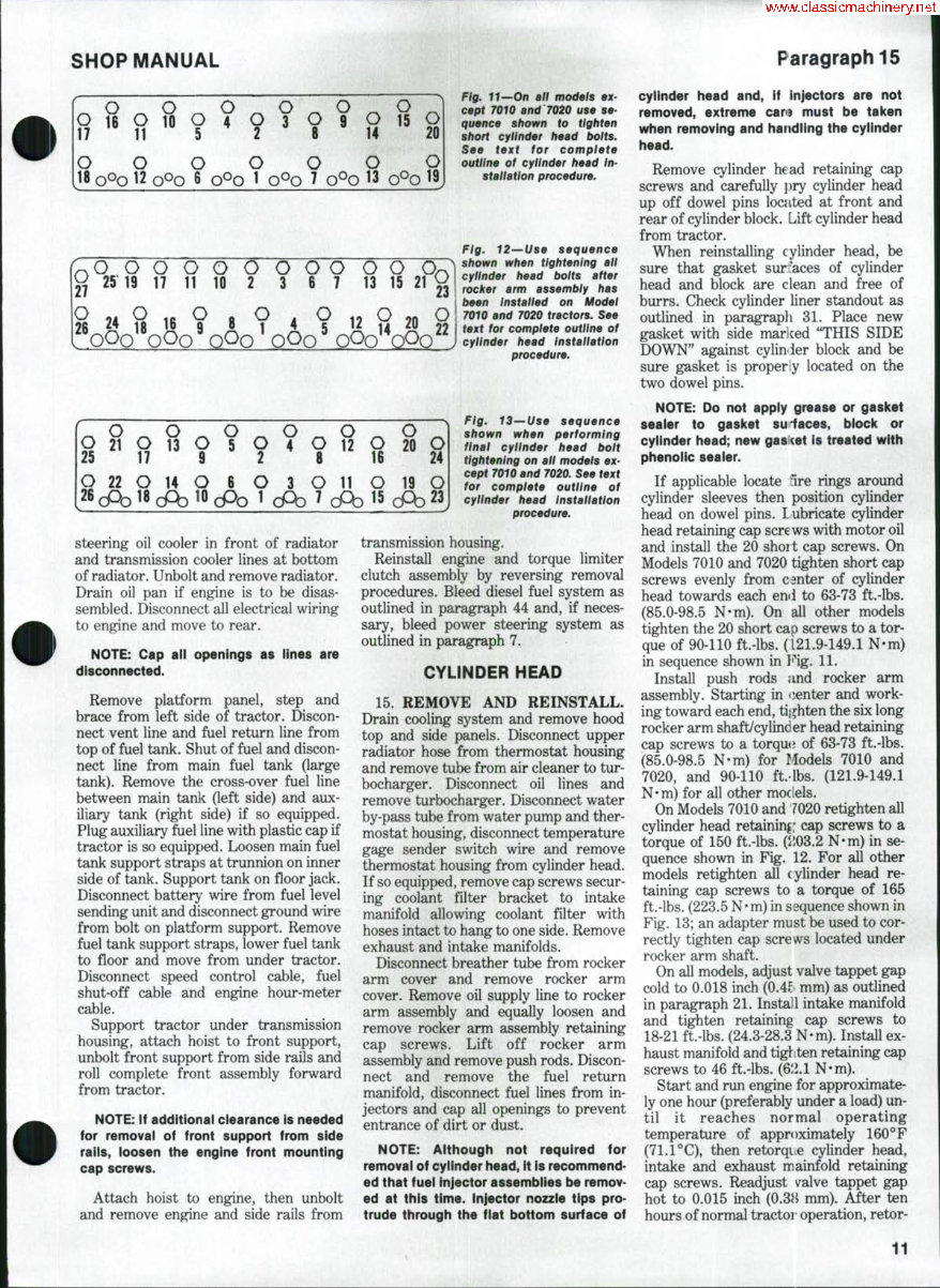
SHOP MANUAL Paragraph 15 U O O O Q <J 18 QQQ 12 QOQ 6 QOQ 1 QOQ 7 QOQ 13 ^O O O O O O O O O O O C ^ 25 19 17 11 10 2 3 6 7 13 15 21 O 26 O IB 16 Q 0 1 4 R IOQQ OOO^QOO^OOQ'* 12 20 23 O 22 o 25 O o 21 22 A: O 17 O )18( o 13 14 :AD O 9 O 10 o 5 6 cPo o 2 O 1 o 4 3 CPD O 8 O 7 O 12 11 CPD O 16 O 15 o 20 19 cPb O 24 O 23 J steering oil cooler in front of radiator and transmission cooler lines at bottom of radiator. Unbolt and remove radiator. Drain oil pan if engine is to be disas- sembled. Disconnect all electrical wiring to engine and move to rear. NOTE: Cap all openings as lines are disconnected. Remove platform panel, step and brace from left side of tractor. Discon- nect vent line and fuel return line from top of fuel tank. Shut of fuel and discon- nect line from main fuel tank (large tank). Remove the cross-over fuel line between main tank (left side) and aux- iliary tank (right side) if so equipped. Plug auxiliary fuel line with plastic cap if tractor is so equipped. Loosen main fuel tank support straps at trunnion on inner side of tank. Support tank on floor jack. Disconnect battery wire from fuel level sending unit and disconnect ground wire from bolt on platform support. Remove fuel tank support straps, lower fuel tank to floor and move from under tractor. Disconnect speed control cable, fuel shut-off cable and engine hour-meter cable. Support tractor under transmission housing, attach hoist to front support, unbolt front support from side rails and roll complete front assembly forward from tractor. NOTE: If additional clearance is needed for removal of front support from side raiis, ioosen the engine front mounting cap screws. Attach hoist to engine, then unbolt and remove engine and side rails from Fig. 11—On all models ex- cept 70i0 and'7020 use se- quence shown to tighten short cylinder head bolts. See text for complete outline of cylinder head In- stallation procedure. Fig. 12—Use sequence shown when tightening all cylinder head bolts after rocker arm assembly has been Installed on Model 7010 and 7020 tractors. See text for complete outline of cylinder head Installation procedure. Fig. 13—Use sequence shown when performing final cylinder head bolt tightening on all models ex- cept 7010 and 7020. See text for complete outline of cylinder head Instaliation procedure. transmission housing. Reinstall engine and torque limiter clutch assembly by reversing removal procedures. Bleed diesel fuel system as outlined in paragraph 44 and, if neces- sary, bleed power steering system as outlined in paragraph 7. CYLINDER HEAD 15. REMOVE AND REINSTALL. Drain cooling system and remove hood top and side panels. Disconnect upper radiator hose from thermostat housing and remove tube from air cleaner to tur- bocharger. Disconnect oil lines and remove turbocharger. Disconnect water by-pass tube from water pump and ther- mostat housing, disconnect temperature gage sender switch wire and remove thermostat housing from cylinder head. If so equipped, remove cap screws secur- ing coolant filter bracket to intake manifold allowing coolant filter with hoses intact to hang to one side. Remove exhaust and intake manifolds. Disconnect breather tube from rocker arm cover and remove rocker arm cover. Remove oil supply line to rocker arm assembly and equally loosen and remove rocker arm assembly retaining cap screws. Lift off rocker arm assembly and remove push rods. Discon- nect and remove the fuel return manifold, disconnect fuel lines from in- jectors and cap all openings to prevent entrance of dirt or dust. NOTE: Although not required for removai of cyiinder head, it is recommend- ed that f uei tnjector assembiies be remov- ed at this time. Injector nozzie tips pro- trude through the fiat bottom surface of cylinder head and, if injectors are not removed, extreme can) must be taken when removing and handling the cyiinder head. Remove cylinder head retaining cap screws and carefully })ry cylinder head up off dowel pins located at front and rear of cylinder block. Lift cylinder head from tractor. When reinstalling cylinder head, be sure that gasket sur'aces of cylinder head and block are clean and free of burrs. Check cylinder liner standout as outlined in paragraph 31. Place new gasket with side marlced "THIS SIDE DOWN" against cylinder block and be sure gasket is properly located on the two dowel pins. NOTE: Do not apply grease or gasket seaier to gasket su laces, biock or cyiinder head; new gasKet is treated with phenolic sealer. If applicable locate ire rings around cylinder sleeves then position cylinder head on dowel pins. Lubricate cylinder head retaining cap screws with motor oil and install the 20 short cap screws. On Models 7010 and 7020 tighten short cap screws evenly from center of cylinder head towards each end to 63-73 ft.-lbs. (85.0-98.5 N'm). On all other models tighten the 20 short cap screws to a tor- que of 90-110 ft-lbs. (L21.9449.1 N-m) in sequence shown in Fig. 11. Install push rods and rocker arm assembly. Starting in center and work- ing toward each end, tighten the six long rocker arm shaft/cylinder head retaining cap screws to a torqu<; of 63-73 ft.-lbs, (85.0-98.5 N-m) for Models 7010 and 7020, and 90-110 ft.-lbs. (121.9-149.1 N'm) for all other models. On Models 7010 and 7020 retighten all cylinder head retaining; cap screws to a torque of 150 ft.-lbs. ($103.2 N-m) in se- quence shown in Fig. 12. For all other models retighten all (ylinder head re- taining cap screws to a torque of 165 ft.-lbs. (223.5 N-m) in sequence shown in Fig. 13; an adapter must be used to cor- rectly tighten cap screws located under rocker arm shaft. On all models, adjust valve tappet gap cold to 0.018 inch (OAt mm) as outlined in paragraph 21. Install intake manifold and tighten retaining cap screws to 18-21 ft.-lbs. (24.3-28.3 N-m). Install ex- haust manifold and tighten retaining cap screws to 46 ft.-lbs. (&.1.1 N-m). Start and run engine for approximate- ly one hour (preferably under a load) un- til it reaches normal operating temperature of approximately 160°F (71.1°C), then retorqie cylinder head, intake and exhaust mainfold retaining cap screws. Readjust v^alve tappet gap hot to 0.015 inch (0.38 mm). After ten hours of normal tractor operation, retor- 11
The repair manual for the Allis Chalmers Model 7080 Tractor is a comprehensive guide designed for professional technicians and do-it-yourself mechanics. It provides essential information for maintaining and repairing the vehicle or engine. The manual covers a wide range of topics including engine removal, wiring diagrams, lubrication points, periodic maintenance, tune-up procedures, disassembly, reassembly, fuel and lubrication systems, electrical system, chassis, suspension, servicing information, tools, and detailed specifications.
It is available in English language and can be delivered instantly in a printable PDF format. The manual is compatible with all versions of Windows and Mac operating systems. It offers step-by-step repair procedures, critical specifications, illustrations, maintenance, cleaning, and reinstalling procedures. Whether obtained as a paper manual or a digital version, it provides the same features and can be accessed immediately for quick problem resolution.
This manual is suitable for individuals with basic knowledge in electrical and mechanical concepts. However, it is advised that those without such knowledge should avoid complex repairs to prevent safety risks. The manual serves as a valuable reference, guiding users through fundamental repair and maintenance processes, enabling them to make informed decisions about their Allis Chalmers Model 7080 Tractor.
Key topics covered in the manual include engine servicing, fuel system service, gearbox, exhaust system, suspension, clutch removal and installation, transmission, cooling system, factory maintenance schedules, electrics, brake servicing procedures, U-joint and CV joint service procedures, timing chain service, exhaust service, and more.
Recently Viewed
5,521,897Happy Clients
2,594,462eManuals
1,120,453Trusted Sellers
15Years in Business
Price:
Actual Price:
Allis Chalmers Model 7080 Tractor Repair Service Manual