

Allis Chalmers Model 616 620 720 Tractor service repair manu
What's Included?
Fast Download Speeds
Online & Offline Access
Access PDF Contents & Bookmarks
Full Search Facility
Print one or all pages of your manual
:.:.:.
:.::.:
.:.:
:::
...
::::::::"'1::::1:1:::,::::1:: ••
This manual covers the following equipment:
Mfg. No.
1690073
1690231
1690288
2020185
2020303
2020304
Description
Model 720 Tractor (Allis Chalmers)
Model 720 Tractor (Allis Chalmers)
Model 720 Tractor (Allis Chalmers)
Model 616 Tractor (Allis Chalmers)
Model 620 Tractor (Allis Chalmers)
Model 620 Tractor (Allis Chalmers)
Repair Manual
Allis Chalmers Model 616, 620, & 720 Tractors
(NOTE: This reprint contains all of the previous Volume 1 & Volume 2 in this one book.)
TP 500-050~-Ol-PM-SA

Thi!S Pa.g~ i!S Bla.nk
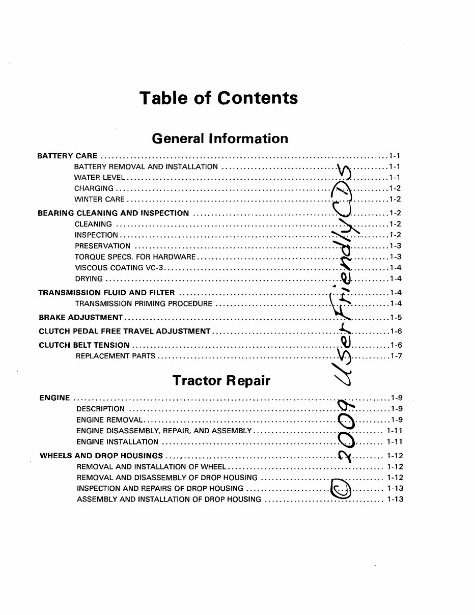
Table of Contents
General Information
BATTERY CARE ............................................................................... 1-1
BATIERY REMOVAL AND INSTALLATION ........ • .................... •..• ............. 1-1
WATER LEVEL ......... •.•..•• .... • ....... •• .... •• .... • ......... • ..................... 1-1
CHARGING ................................ ~ •..• ......... • .......................... •. 1-2
WINTER CARE .................................... • .... •• .......................... •.. 1-2
BEARING CLEANING AND INSPECTION ...................................................... 1-2
CLEANING ................... •. 0 ••••••••••••••••••••••••• 0.0 ••• 0 0 •••••••• 0 •••••••••• 0 1-2
INSPECTION .............. • ......... • 0 ••••••••• 0 ••• '0' •••• 0 0 ••••••••••••••••••••••• 0 ••• 1-2
PRESERVATION ............ •..• ..... ••.••• ..... ••. 0 •• 0 ••• 00 ••••••••••• 0 •••• 0 ••••••••• 1-3
TORQUE SPECS. FOR HARDWARE ..••.•..• 0 • 0 ••••••••••••••••••••••••••••••••••••••••• 1-3
VISCOUS COATING VC-3 .... 0 •••••••••••••••••••• 0 •••••••••••••••••••••••••••••••••••• 1-4
DRYING ............... •.•..• 0 •••• '0' •••••••• 0 •••••••••••••••••••••••••••••••••••••••• 1-4
TRANSMISSION FLUID AND FILTER .......................................................... 1-4
TRANSMISSION PRIMING PROCEDURE .•.•..• ..... •...•.••...• .... • ................ •.• 1-4
BRAKE ADJUSTMENT . ... : .................................................................... 1 -5
CLUTCH PEDAL FREE TRAVEL ADJUSTMENT . ................................................ 1-6
CLUTCH BELT TENSION ... .................................... 0 ••••••••••••••••••••••••••••••• 1-6
REPLACEMENT PARTS ....... 0 ••••••••••••••••••••••••• 0 •••••••••••••••••••••••••••••• 1-7
Tractor Repair
ENGINE .................................................................... o •••••••••••••••••• 1-9
DESCRIPTION ..... •• ......... • ...... ••..• ......... ••• .................. •.. 0 • 0 •• 0 ••••• 1-9
ENGINE REMOVAL • .............. •..•••.•. '0' 0 ••••••••••••••••••• 0000.00 •••••••••••••• 1-9
ENGINE DISASSEMBLY, REPAIR, AND ASSEMBLY. 0 0 ••••••••••••••••• 0 •••••••••••• 0 •• 1-11
ENGIN E INSTALLATION ............... • .... • ..... • ..... •. 0 • • • • • • • • • • • • • • • • • • • • • • • • •• 1-11
WHEELS AND DROP HOUSINGS . ......... 0 •••••••••••••••••••••• 0 ••• 0 ....................... 1-12
REMOVAL AND INSTALLATION OF WHEEL • ......... •.• .... ••..• .... •...• ..... • ...... 1-12
REMOVAL AND DISASSEMBLY OF DROP HOUSING .•..• ........ •...• .... •...•... 0 ••• 1-12
INSPECTION AND REPAIRS OF DROP HOUSING •••• .... • 0 •••••••••••••• 0 ••••••••••••• 1-13
ASSEMBLY AND INSTALLATION OF DROP HOUSING .... •.•...• o •••••••••••••••• 0.0 •• 1-13
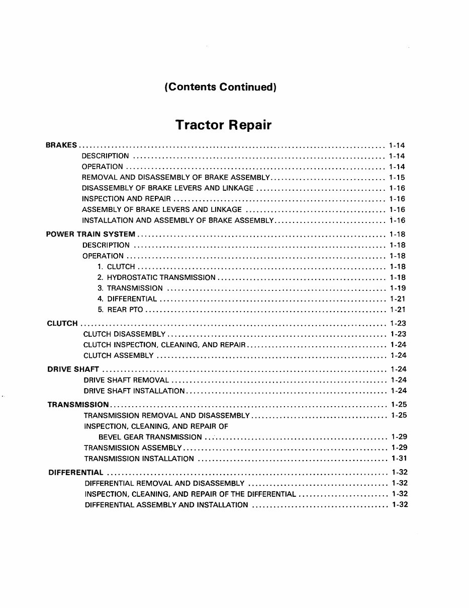
(Contents Continued)
Tractor Repair
BRAKES. . . . . . . . . . . . . . . . . . . . . . . . . . . . . . . . . . . . . . . . . . . . . . . . . . . . . . . . . . . . . . . . . . . . . . . . . . . . . . . . . . . .. 1-14
DESCRIPTION .................. ••..• ..... •..• ........... • .............. • .......... • 1-14
OPERATION ....... •...• ...... •.•...•...•••••• .......... •• ............. •• ...... •.•.. 1-14
REMOVAL AND DISASSEMBLY OF BRAKE ASSEMBLY •.•..••..• ......... • .... • ....... 1-15
DISASSEMBLY OF BRAKE LEVERS AND LINKAGE ......... •.•.• .......... • ........... 1-16
INSPECTION AND REPAIR ...• ....... •.••••.•.•• .......... •.• ..... • ..... •••...•••...• 1-16
ASSEMBLY OF BRAKE LEVERS AND LINKAGE ..• ........... • ..... •.•..•••.•.•.•••.•• 1-16
INSTALLATION AND ASSEMBLY OF BRAKE ASSEMBLy ...... • ..... •.••.•• .... •• ...... 1-16
POWER TRAIN SYSTEM .. ............................ _ ....................................... 1-18
DESCRIPTION .• ..... • .... ••...•...• .... • ...... •...• ...... • ........ •.• .... •• ...... •. 1-18
OPERATION •.. . . . . . • . . . . . . . . . . . . . . . . . . • . . . . . . . • . • • • . • . . . . • . . . • • • • • • . . . . . . • . . . . . . . .. 1-18
1. CLUTCH .. . . . . . . . . . . . . . • . . • • • • . . . . . . . . . . . . • • • • . . • . . . • . • • • • . . • . . . . . . . • . . . . . • •. 1-18
2. HYDROSTATIC TRANSMISSION. . . . . . . . . . . • . • . • . . • . . • . • • • • . . . . . . . . . • . . . . . . . • .. 1-18
3. TRANSMISSION ...... •..•.• ............... •.•••••••..••• ........ •..•••...•.. 1-19
4. DI FFERENTIAL . • • . . . • • • . . • • . . • . • . • • • • • • • . . . . • • • • • • • . . • • . • . . . • . . . • . • • . . • . . . • .• 1-21
5. REAR PTO ............... •...•••..•••.•• ....... •.••.••• ..... ••..•••...••••.•• 1-21
CLUTCH . . . . . . . . . . . . . . . . . . . . . . . . . . . . . . . . . . . . . . . . . . . . . . . . . . . . . . . . . . . . . . . . . . . . . . . . . . . . . . . . . . . .. 1-23
CLUTCH DISASSEMBLY ................ •• .... •.•..• ........ • ..... ••••••...•.• ....... 1-23
CLUTCH INSPECTION, CLEANING, AND REPAIR .... •••..• .... • .... • .... • .... • ....... •. 1-24
CLUTCH ASSEMBLY ..•.••.•.••..••...•...• ........ •••..•.•...••• ......... •• ...... •. 1-24
DRIVE SHAFT ............................................................................... 1-24
DRIVE SHAFT REMOVAL. • • . • • . • . • . . • • • . . • . • . • • . . . . . . . . . • • . • • • . . . . . . . . . . . • . . . . • . • • .• 1-24
DRIVE SHAFT INSTALLATION •..• ....... •.•••.• ............. ••• ..... •...•••...••••.•. 1-24
TRANSMISSION . ............................................................................ 1-25
TRANSMISSION REMOVAL AND DISASSEMBLY .... •• .... • ..... ••••••••..••..•..•..•. 1-25
INSPECTION, CLEANING, AND REPAIR OF
BEVEL GEAR TRANSMISSION •• .- ................................................ 1-29
TRANSMISSION ASSEMBLY •••.••• .... • .... ••.• ....... •.•••.••••...• .... •••..•••.••. 1-29
TRANSMISSION INSTALLATION ..... •.••••.•.•• ....... •...•.•• .... ••••.••••.•••••..• 1-31
DIFFERENTIAL .............................................................................. 1-32
DIFFERENTIAL REMOVAL AND DISASSEMBLY ...••••••••..••.•••••• .... •.•••.• ..... • 1-32
INSPECTION, CLEANING, AND REPAIR OF THE DIFFERENTIAL •••••••...•.•.••.•••.•••. 1-32
DIFFERENTIAL ASSEMBLY AND INSTALLATION •.•••••••.•••••••...•.•.•.••..•••••••• 1-32
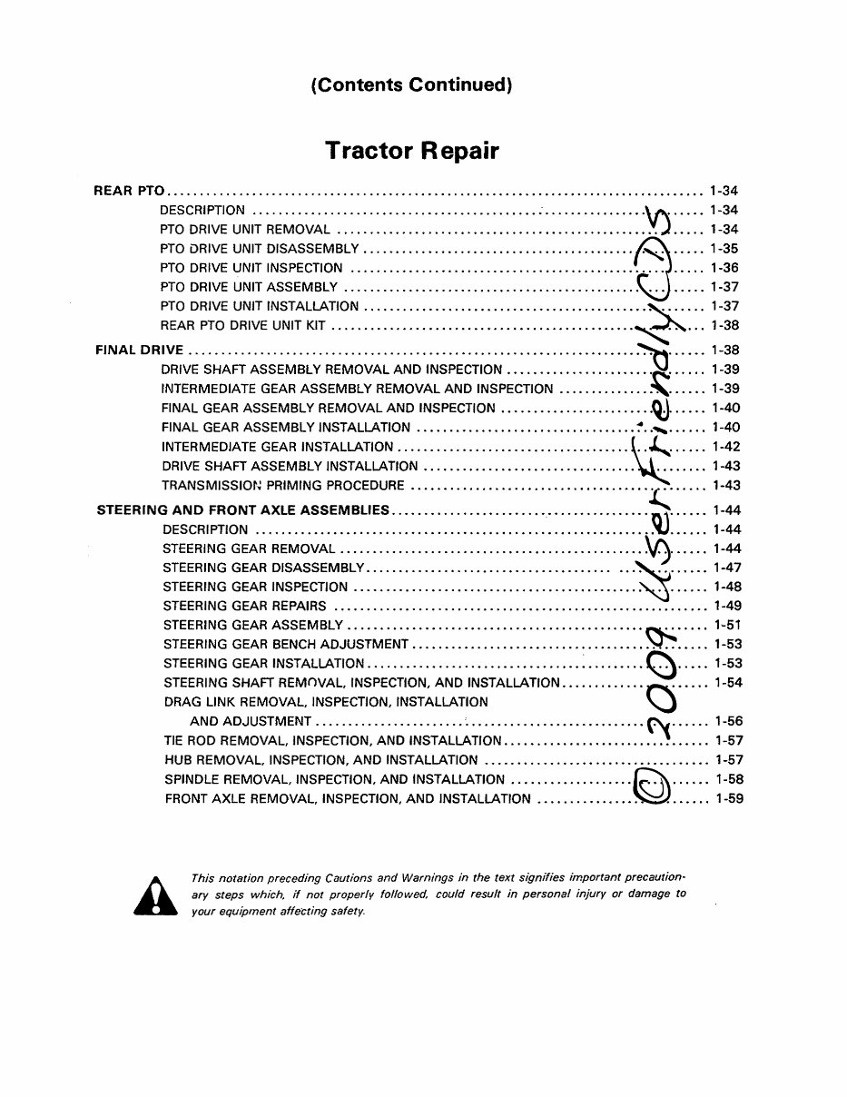
(Contents Continued)
Tractor Repair
REAR PTO .............. .. " ................................................................. 1-34
DESCRIPTION .................... • ...... •••••• ......... ••• -.......... ••.•• .... •.•..• 1-34
PTO DRIVE UNIT REMOVAL • ........ •..• ........ •••••.••...••• ...... •..•••...••••... 1-34
PTa DRIVE UNIT DISASSEMBLY. . . . • . . . . . • • • . . . . . . . . . . . • . • . . . . . . • . • . . . • . . • . • . . • . . . •• 1-35
PTO DRIVE UNIT INSPECTION ....... ••••...• .... ••.••••..•..•..• ....... ••••...•.•... 1-36
PTa DRIVE UNIT ASSEMBLY .... ••.• ...... •..•• ....... •• ............ •• ...... ••.•••.. 1-37
PTO DRIVE UNIT INSTALLATION ...... • ..... •• ..... • ..... ••• ..... ••• ..... ••.•..•.•.•• 1-37
REAR PTO DRIVE UNIT KIT .•.•• ...... •••••..••..•.••••••...••• ...... •..•..•.••.• .... 1-38
FINAL DRIVE . ............................................................................... 1-38
DRIVE SHAFT ASSEMBLY REMOVAL AND INSPECTION. • • . • • • • • • • . . . . . . . . • • • . . • • • • . .. 1-39
INTERMEDIATE GEAR ASSEMBLY REMOVAL AND INSPECTION ...••.•...•.•.•.•.•.•.• 1-39
FINAL GEAR ASSEMBLY REMOVAL AND INSPECTION •••.••••••.•••..•...••.• .... •.•• 1-40
FINAL GEAR ASSEMBLY INSTALLATION •.••..••••••.•.••...••• ..... •• ..... •..•.• .... 1-40
INTERMEDIATE GEAR INSTALLATION • .... •.•..• ..... ••..•• ...... ••••.••.••.•••...••• 1-42
DRIVE SHAFT ASSEM BLY INSTALLATION • ...... •••••••••..•••••• .... • .... •.•.••.•.•• 1-43
TRANSMISSION PRIMING PROCEDURE .•••••.••.• .... •..•..• .... •..••...•••..••• .... 1-43
STEERING AND FRONT AXLE ASSEMBLIES . ................................................ 1-44
DESCRIPTION ..... •.•.•..•••• ..... •.•••••.•••••••• .... • ....... •...••..••••..•.••.•. 1-44
STEERING GEAR REMOVAL ..... •..• ...... •••.• ..... ••..•••...•.•..•...•.•.•• .... ••• 1-44
STEERING GEAR DISASSEMBLY. . . . . . • • • • • . . . . . . • • • . • • • • . . . • • • • • • • • .• • .••.• .... •.•• 1-47
STEERING GEAR INSPECTION .••••.•..•..•••.•••••...••.• .... ••• .... •..•..•..••••... 1-48
STEERING GEAR REPAIRS ..•...• .... •.•...••...• .... ••.•••• .... •••.•.•..•••.•.•.••• 1-49
STEERING GEAR ASSEMBLy ••.•.•.•••••••...••••••••.••..•••••.••..•••.•••..••..••. 1-51
STEERING GEAR BENCH ADJUSTMENT ...•••••• ......... •• ......... ••...•.• .... ••... 1-53
STEE RI NG GEAR INST ALLATfON . . . . . . . • . • • . . • . . . • . . . • • . • . • • . . . • • • • • . . • . . . • . • • • . . . • •• 1-53
STEERING SHAFT REMOVAL, rNSPECTION, AND INSTALLATION .•• .... ••.••••..••••..• 1-54
DRAG LINK REMOVAL, INSPECTION, INSTALLATION
AND ADJUSTMENT •.•..• ....... ••.•.•...• ' ..•••••.••..•••••••••.•••.••••••...••. 1-56
TIE ROD REMOVAL, INSPECTION, AND INSTALLATION •..••...•.• .... •••.••.•..••••..• 1-57
HUB REMOVAL, INSPECTION, AND INSTALLATION •••••••..••.•••••..•.•..•.• ..... ••. 1-57
SPINDLE REMOVAL, INSPECTION, AND INSTALLATION .••...•••••.••..•..•••• ..... ••• 1-58
FRONT AXLE REMOVAL, INSPECTION, AND INSTALLATION •• ........ •..••.••..•••.•.. 1-59
This notation preceding Cautions and Warnings in the text signifies important precaution-
ary steps which. if not properly followed could result in personal injury or damage to
your equipment affe'Cting safety.
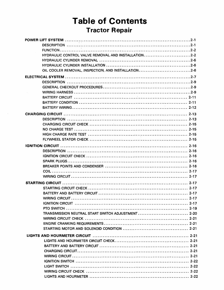
Table of Contents
Tractor Repair
POWER LIFT SYSTEM . ........................................................................ 2-1
DESCRIPTION .•••.• ...... •.• ..... •..• ........ • ......... •• ............ •.••.•.•.•.••... 2-1
FUNCTION .••..•.••... ~ ..•.•..•...• ..... •••...•..• ...... ••..•..•.• .... ••••••••.••••..• 2-2
HYDRAULIC CONTROL VALVE REMOVAL AND INSTALLATION ••••...••..• ...... ••...••.. 2-2
HYDRAULIC CYLINDER REMOVAL .• ...... ••..••.•• ...... •••.••••.•••.•••..• ...... ••... 2-6
HYDRAULIC CYLINDER INSTALLATION •...••.•••.•••••...••.••••..••••••...•..•••.• .... 2-6
OIL COOLER REMOVAL, INSPECTION, AND INSTALLATION •.•••••••••••••• ...... •.••.••• 2-6
ELECTRICAL SYSTEM . ........................................................................ 2-7
DESCRI PTION .• .... • 0 ••••••••••••••••••••••••••••••••••••••••••••••••••••••••••••••••• 2-9
GENERAL CHECKOUT PROCEDURES •••••.•.•••••.••••••••••...•..• ...... ••.•.•• .... •.. 2-9
WIRING HARNESS ........ •• .... •••.••••...••••••...••••••• ............ ••.•••••..•••.. 2-9
BA TIERY CIRCUIT ••.•...•••..•.•••••.•••..•••••••.•.•• ' ••••.•.• ....... ••••.••••...•• 2-11
BATIERY CONDITION .•.•••••.•.••.••••••.••..••• .... ••••••.•••..•..•.••••••.• ...... 2-11
BA TIERY WI RING •••..••.••••••.•...••••••••.••• .... ••.••••••.•...•.•.• '. • • • • • • . . . • •• 2-12
CHARGING CIRCUIT ........................................................................ 2-13
DESCRI PTION .•.•••.•••••.••••••...•.•.•••.•.••••...•..•..•••••••••••••..•..•••.••. 2-13
CHARGING CIRCUIT CHECK •.•.•..••• .... ' ••.•••.•••••.•..•.•••••••••••••.••.•.••.••. 2-15
NO CHARGE TEST ...••.• .... ••.••••..•..••.•••••••••••..••••••••••••.••••..••••.••. 2-15
HIG H CHARGE RATE TEST .•...•.•.••.••.•••••••••••••..•••••••.•••.•••.•••...••.•.. 2-15
FLYWHEEL STATOR CHECK . . . . . • • • • • • • • . • . • . • • • • • • • • • • . . • • • • • . . . • . . • • . • • • • • • . • . • . •. 2-15
IGNITION CIRCUIT .......................................................................... 2-16
DESCRIPTION ..••.• .... •••••.•.••..••••...••••••..•••••••••..•.•• ..... •••••••••••.. 2-16
IGNITION CIRCUIT CHECK .•••.•..•..•••••...•••••..••••••••••.•..• .... ••••••.•...••• 2-16
SPARK PLUGS .••••••..•••••.••...••..•.•••..••• ..... ••.••.••.••..•••••..••••••...•• 2-16
BREAKER POINTS AND CONDENSER .......................... ',' ..•••••..••..••..••• 2-16
COIL . • • • • . . . • • • . . • • • • • • • . . • . . . • . • • . . . . • • • • . . . • • . • . • • . • . • • • • • • • • • . • • • . • • . . • • . . • . . . •. 2-17
WIRING CIRCUIT .... ••••••...•.••••••...•••.•.•••••.•...•.•.••••••.•.••..•• .... •.•.. 2-17
STARTI NG CI RCUIT . . . . . . . . . . . . . . . . . . . . . . . . . . . . . . . . . . . . . . . . . . . . . . . . . . . . . . . . . . . . . . . . . . . . . . . .. 2-17
STARTING CI RCUIT CHECK. . • • . . • • • • • • • • . . . • • . . • • • • • • • . • • • • • • • • • • • • • • • . • • • • . • . • • • • •. 2-17
BATIERY AND BATIERY CiRCUiT ••..••••..••••..•••••••..••••••.••...•.••••••.••.•.. 2-17
WIRI NG CIRCUIT. • • • . . • . • • . • • . • . • . . . • • • • • . • • • • • • • • • • • • • • . • • • • • • • • • . . . • . • • • • • • . • . • . .. 2-17
IGNITION CI RCUIT •••.•.•••••••..•..•••••...••••••••••.••••..•...••..•.••••••••.••.. 2-17
PTO SWITCH ..•.••..•••.. " •.•• .... •.••••.. " •.••••.•.•••••• .......... ••••.•••.•.•.•• 2-19
TRANSMISSION NEUTRAL START SWITCH ADJUSTMENT ••••..••..•.•..••..•••.•••.•• 2-20
WIRING CIRCUIT CHECK •• "0 ••• " ••••• "" •••••••••••••••••••••••••••••••••••••••••••••• 2-21
ENGINE CRANKING REQUIREMENTS •...•..•.•••••••...•.••..••••..••••.•..••..•••••• 2-21
STARTING MOTOR AND SOLENOID CONDITION •••••••.•.••.•••••••••••.•••••..•••••. 2-21
LIGHTS AND HOURMETER CiRCUiT .................................................. ...... 2-21
LIGHTS AND HOURMETER CIRCUIT CHECK ..•••••.••..••.•••••••••••••••••••.••••••.. 2-21
BATIERY AND BATIERY CiRCUiT .•••..•.• .... ••• ..... ••..•••••...•..•••••••••.•••... 2-21
CHARGING CIRCUiT.. . . • . . • • • . . • • • • . . . • . . • • . . . • • . . . . . • • • • • • • • • . . . • . . . • • . . . • • • • • • • • •• 2-21
WIRING CIRCUIT .•• ....... •••...••••...••••..••• ...... •• ......... •.•.••.•.•.•.•...•• 2-21
IGNITION SWITCH •••.••...•..•••••••..•.••...•• ...... •.••..•.. " .................... 2-22
LIGHT SWITCH .•••••.••••••.••.•...•.••.••.•.•..•••..•.•...•.•.•.•••••••.•...•..••. 2-22
WIRING CIRCUIT CHECK •••••••..•..••••..•.• .... •••..•.•..••.••..•••••••••...••.••. 2-22
LIGHTS AND HOURMETER ••••• ..... •.••..•••••.•••••••••..••.•••.•••••••••••.•••••• 2-22
(Contents Continued)
Tractor Repair
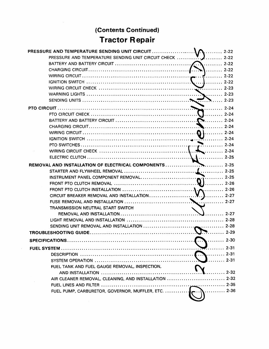
PRESSURE AND TEMPERATURE SENDING UNIT CiRCUiT ....... • ........................... 2-22
PRESSURE AND TEMPERATURE SENDING UNIT CIRCUIT CHECK .... •••• ....... •.•.•.. 2-22
BATTERY AND BATTERY CiRCUiT ••• ....... •..••.••...• ..... •..•...•.••...•...••••... 2-22
CHARGING CiRCUiT ...•...•..•.•.• ....... ••••...••• ........ ••.•• .... ••...• .......... 2-22
WIRING CIRCUIT .... • .... •.•..•.• ........ ••• ..... • ...... •..••..•.• .... ••••...•.• .... 2-22
IGNITION SWITCH ............. •.• ......... • ..... •••.••• ...... • ......... •• ..... • .... 2-22
WIRING CIRCUIT CHECK ........ • ....... •.•• ..... ••••••.• ...... • ........ ••.••..• .... 2-23
WARNING LIGHTS ............ •..•...•• .............. ••••..• .......... •..•.•• ....... 2-23
SENDING UNITS ......... • .......... ••••• ..... ••..•.•...•• .............. •...• ..... •• 2-23
PTO CIRCUIT ................................. • .................... • ........ •.• .............. 2-24
PTO CI RCUIT CHECK . . . . . . . . • • . . . . . • . • . • . • . . . • . . • . . . . . . . . . • • . . . . . • • • • • . • . . • . • . • . • • .. 2-24
BATTERY AND BATTERY CiRCUiT ••.•.•...••.••..••...• ..... ••...••.•• ......... •.•... 2-24
CHARGING CIRCUIT ...• ..... ••..•..• ..... •••• .... • ......... •..••.••...•• ..... •• ..... 2-24
WIRING CIRCUIT • ...... ••..•..•.•.•• ...... ••• .... •.•.• ...... •••••.•.••.•.• .... •.•... 2-24
IGNITION SWITCH .... • ..... •..•.•••..• .... •• ..... ••••..•..•••••..•.• .... • ..... • .... 2-24
PTO SWITCHES ...• ...... •..•.•.•• .... •..• ........ •••••••...•.••..• .... ••• ..... • .... 2-24
WIRING CIRCUIT CHECK ...... ••••..•.•.• ...... •..••••••••..•••...•.•.•.••..•.•••... 2-24
ELE-CTRIC CLUTCH ..• .......... • .... •.•.• ...... •..•.••••••.•• ......... •.••.•.•.• .... 2-25
REMOVAL AND INSTALLATION OF ELECTRICAL COMPONENTS .•..• ............ • .......... 2-25
STARTER AND FLYWHEEL REMOVAL ......................................... - ••. ° 0 ••• 2-25
INSTRUMENT PANEL COMPONENT REMOVAL. .•.• ..... ••.••• .... • ..... •..•.••..•.••. 2-25
FRONT PTO CLUTCH REMOVAL ..................................................... 2-26
FRONT PTO CLUTCH INSTALLATION ................................................. 2-26
CIRCUIT BREAKER REMOVAL AND INSTALLATION .................................... 2-27
FUSE REMOVAL AND INSTALLATION ................................................ 2-27
TRANSMISSION NEUTRAL START SWITCH
REMOVAL AND INSTALLATION •• ..... •••• .... • ...... •.••...•••.• ........ ••..•.•. 2-27
LIGHT REMOVAL AND INSTALLATION ............................................... 2-28
SENDING UNIT REMOVAL AND INSTALLATION .... •.•...•...•••••••..•..•.•...•.••••. 2-28
TROUBLESHOOTING GUIDE ......................... •••..••• ............... • ........... • .... 2-29
SPECIFICATIONS ........................... • ..... • ...... ••• ........... ••..••...• ............ 2-30
FUEL SYSTEM ......................... • ....... •...•...•.• ....... • ...... •.• ...... • ........... 2-31
DESCRIPTION ...••.•...•••••••• .... ••• .... •.• .... ••••..•..•.•.••.••..•.••..•..••••. 2-31
SYSTEM OPERATION ...• .... ••.•..••.••• .... •.•...•••••..••.••• ...... •.•..• .... ••.. 2-31
FUEL TANK AND FUEL GAUGE REMOVAL, INSPECTION,
AND INSTALLATION .... •.•..•••..•.•..••.••...•...••..••.•.•..•.•••..•••..• .... 2-32
AIR CLEANER REMOVAL, CLEANING, AND INSTALLATION •• .... ••• ..... •••.• ......... 2-32
FUEL LINES AND FILTER ............... •••.•• .... ••...•..•..••.•..•• .......... • ..... 2-35
FUEL PUMP, CARBURETOR, GOVERNOR, MUFFLER, ETC .••.•• ........ •• .... •..•.•.•.. 2-36
(Contents Continued)
Tractor Repair
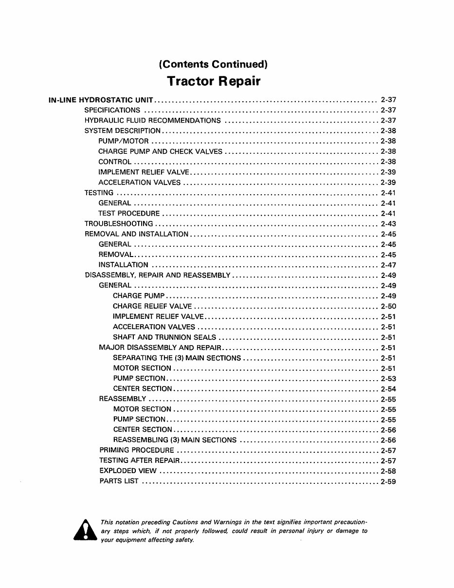
IN-LINE HYDROSTATIC UNIT . ............................................................... 2-37
SPECIFICATIONS ..•••.•.•• .... ••• ...... •...••••..••••••..•.•••..•.•...•.•.•...• .... 2-37
HYDRAULIC FLUID RECOMMENDATIONS •••.••.•.•.• .... ••.•••.••••.••.• ............ 2-37
SYSTEM DESCRIPTION •..•.•...••• ........ •••.••..•••.••••• .... ••..•..••••••.••• .... 2-38
PUMP IMOTOR •.•.• ..... ••...••••.••••••.•.•.•.•..• .... ••.•..••• ....... ••• ..... 2-38
CHARGE PUMP AND CHECK VALVES ............................................ 2-38
CONTROL ..•.••.•••.•...••.•.••••••••.••.••••••• ......... ••••••••••••...• ...... 2-38
IMPLEMENT RELIEF VALVE .•••.• .... •.••••..••••••• .... •••••••••..••••.•.• ...... 2-39
ACCELERATION VALVES ..•• .... • .... ••••••••••.• ..... ••••.•..•..••••..••.• ..... 2-39
TESTING ...... •..•.••• ...... •...•...• ...... ••.••.•••..•.••...•..•••.•.•••..•..•••.. 2-41
GENERAL .... •••..•.••••.•..•••.•.••••••...••...•••••••.••.•••••••••.••.••..••. 2-41
TEST PROCEDURE •.••..••..••..••..•.•••••••••••..•...••..••.••..••.•...••.•..• 2-41
TROUBLESHOOTING ...••••••.•.••••.•••••.•••.••••..•••••.••...•.••.•.••..•.•••.•.• 2-43
REMOVAL AND INSTALLATION ••••..••..••.••.•••...•.•..•..•.•..•.••.•••••.•.•.•... 2-45
GENERAL ..•...•..••••.•••••.••.•.••.•••...•••••••••••..••.•••••..•...•.•..•..• 2-45
REMOVAL .•...••••••.•.••.•••.•..•...•...•••...•••..••.•••.•.••..•••••••.••••.. 2-45
INSTALLATION .... •••••.••..•••.••••••••..•••••••••••.•••••••••••.••.•.•.••••.. 2-47
DISASSEMBLY, REPAIR AND REASSEMBLy .••••.••...•..•••...•.•••.•.•••••••..•..•• 2-49
GENERAL •.•••..•••••••••...•••.•••••••••.•••.••••••••...•.•••••• .... ••••.•.••. 2-49
CHARGE PUMP ...• .... •.•...••••.•••••••.•••••.•••••.••..••••••.•..•••.•.•• 2-49
CHARGE RELIEF VALVE ...••.•••••••••..••••.••••••••••••••••.••..•.•..•.••• 2-50
IMPLEMENT RELIEF VALVE •..•••••.•••••.•• .... ••• .... •.•.•..••••••••.•••.•. 2-51
ACCELERATION VALVES .•••.••••••.•.••••••••••.••...•••••.••.•..•••..•••.. 2-51
SHAFT AND TRUNNION SEALS ...••.•••..•..•..•.••.•.•.••••.•.•.••. '" ...•• 2-51
MAJOR DISASSEMBLY AND REPAIR ............................................. 2-51
SEPARATING THE (3) MAIN SECTIONS ••.••••...• ...... ••..•.•••••••.•••••.•• 2-51
MOTOR SECTION .•••••.••••.••.•••.•..•••••.•••••.•.•••••••...•...•..•••••. 2-51
PUMP SECTION .•.•...•••••••• .... •.•••.•••••••••••.•..•••••••.•••.•.••..•.. 2-53
CENTER SECTION ••••••..•••••••••••••••••.•.•.••••.••••••.••.••..••.•••••.• 2-54
REASSEMBLY •••..•..•...••••..•...•..••••.•.•••••••...•.•••.•.••.•.•.••.•.•••. 2-55
MOTOR SECTION ••••.•.•.••.•••••••••••••.•.•••••••.••••••.•••...•.•.•••••• 2-55
PUMP SECTION .•.•..••.••..•...•••••••••.•••..••••• ' •.•••.••.••.••••.••.•••• 2-55
CENTER SECTION ..•.••..••••••••••• ..... ••••••.•••••••••••.••.•••.•••.•.•.• 2-56
REASSEMBLING (3) MAIN SECTIONS ••••.••• ..... •.•.••••.•.••.••••••.•••... 2-56
PRIMING PROCEDURE •••••..••••.•••••••.•••••••••••••.••••••••••.••.•••.•••... 2-57
TESTING AFTER REPAIR .... ••••..•••.•••..••••••.• ...... ••••••..••••••••••.•.••.• 2-57
EXPLODED VIEW ••••••••••..•••••••••••••.•••••••••.••••••••••••••.•••••.••••.• 2-58
PARTS LIST ••••••..••..••••••..•.•.•••..•••..•.•..•...••••••.•.•••••••••.••..•. 2-59
A
This notation preceding Cautions and Warnings in the text sigmlies important precaution-
ary steps which if not properly followed, could result in personal injurv or damage to
your equipment affecting safety.
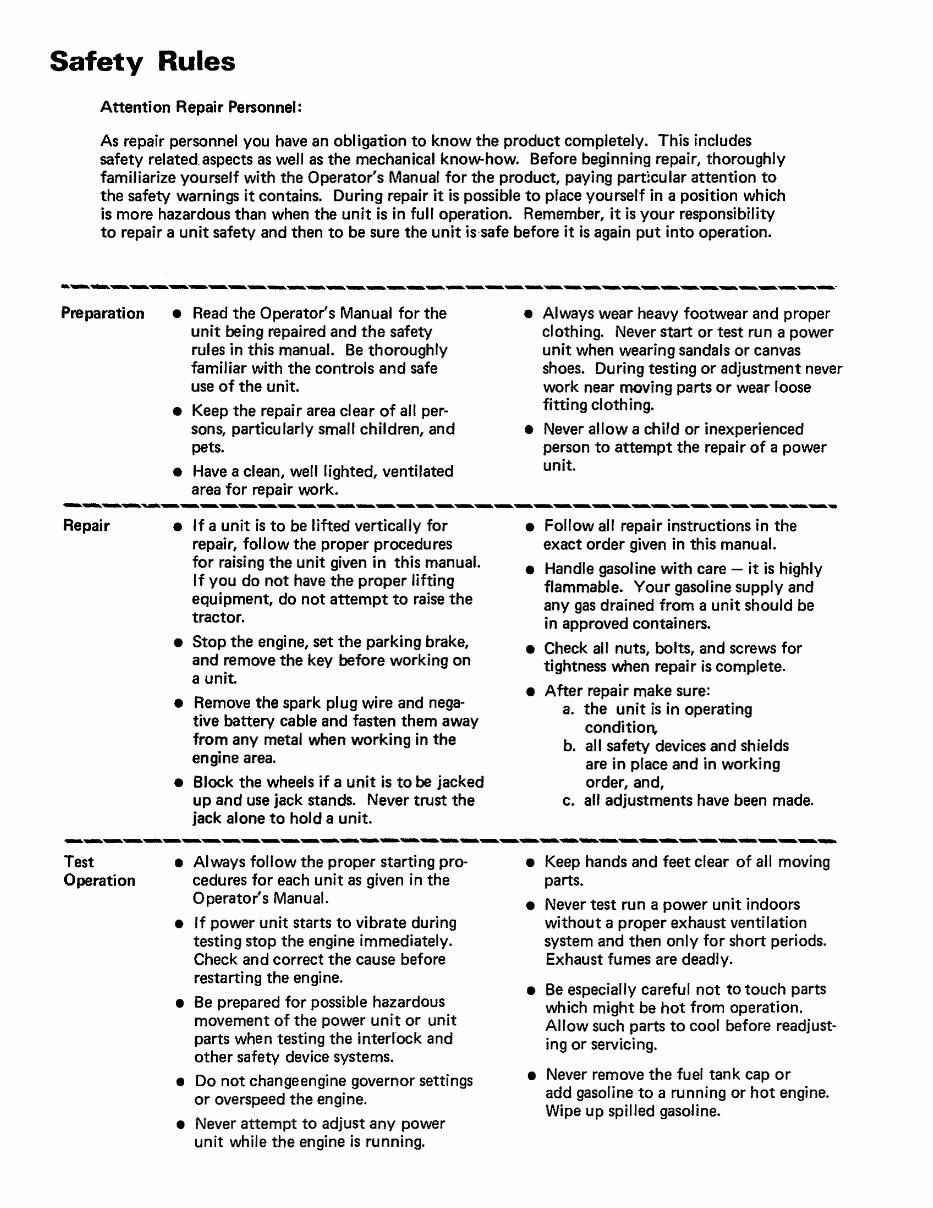
Safety Rules
Attention Repair Personnel:
As repair personnel you have an obligation to know the product completely. This includes
safety related. aspects as well as the mechanical know-how. Before beginning repair, thoroughly
familiarize yourself with the Operator's Manual for the product, paying part:cular attention to
the safety warnings it contains. During repair it is possible to place yourself in a position which
is more hazardous than when the unit is in full operation. Remember, it is your responsibility
to repair a unit safety and then to be sure the unit is·safe before it is again put into operation.
Preparation • Read the Operator's Manual for the
Repair
unit being repaired and the safety
rules in this manual. Be thoroughry
familiar with the controls and safe
use of the unit.
• Keep the repair area clear of alt per-
sons, particu tarly small children, and
pets.
• Have a clean, well lighted, ventilated
area for repair work.
• If a unit is to be lifted vertically for
repai r, follow the proper procedu res
for raising the unit given in this manual.
If you do not have the proper lifting
equipment, do not attempt to raise the
tractor.
• Stop the engine, set the parking brake,
and remove the key before working on
a unit.
• Remove the spark plug wire and nega-
tive battery ca ble and fasten them away
from any metal when working in the
engine area.
• Block the wheels if a unit is. to be jacked
up and use jack stands. Never trust the
jack alone to hold a unit.
• Always wear heavy footwear and proper
clothing. Never start or test run a power
unit when wearing sandals or canvas
shoes. During testing or adjustment never
work near moving parts or wear loose
fitting clothing.
• Never allow a child or inexperienced
person to attempt the repair of a power
unit.
• Follow all repair instructions in the
exact order given in this manual.
• Handle gasoline with care - it is highly
flammable. Your gasoline supply and
any gas drained from a unit should be
in approved containers.
• Check all nuts, bolts, and screws for
tightness when repai r is complete.
• After repair make sure:
a. the unit is in operating
condition,
b. all safety devices and shields
are in place and in working
order, and,
c. aU adjustments have been made.
---------------------------------------
Test
Operation
• Always follow the proper starting pro-
cedures for each unit as given in the
Operator's Manual.
• If power unit starts to vibrate during
testing stop the engine immediately.
Check and correct the cause before
restarting the engine.
• Be prepared for possible hazardous
movement of the power unit or unit
parts when testing the interl'ock and
other safety device systems.
• Do not changeengine governor settings
or overspeed the engine.
• Never attempt to adjust any power
unit while the engine is running.
• Keep hands and feet clear of alJ moving
parts.
• Never test run a power unit indoors
without a proper exhaust ventilation
system and then only for short periods.
Exhaust fumes are deadly.
• Be especially careful not to touch parts
which might be hot from operation.
Allow such parts to cool before readjust-
ing or servicing.
• Never remove the fuel tan k cap or
add gasoline to a running or hot engine.
Wipe up spilled gasoline.
Battery Care
General Information
BATTERY CARE
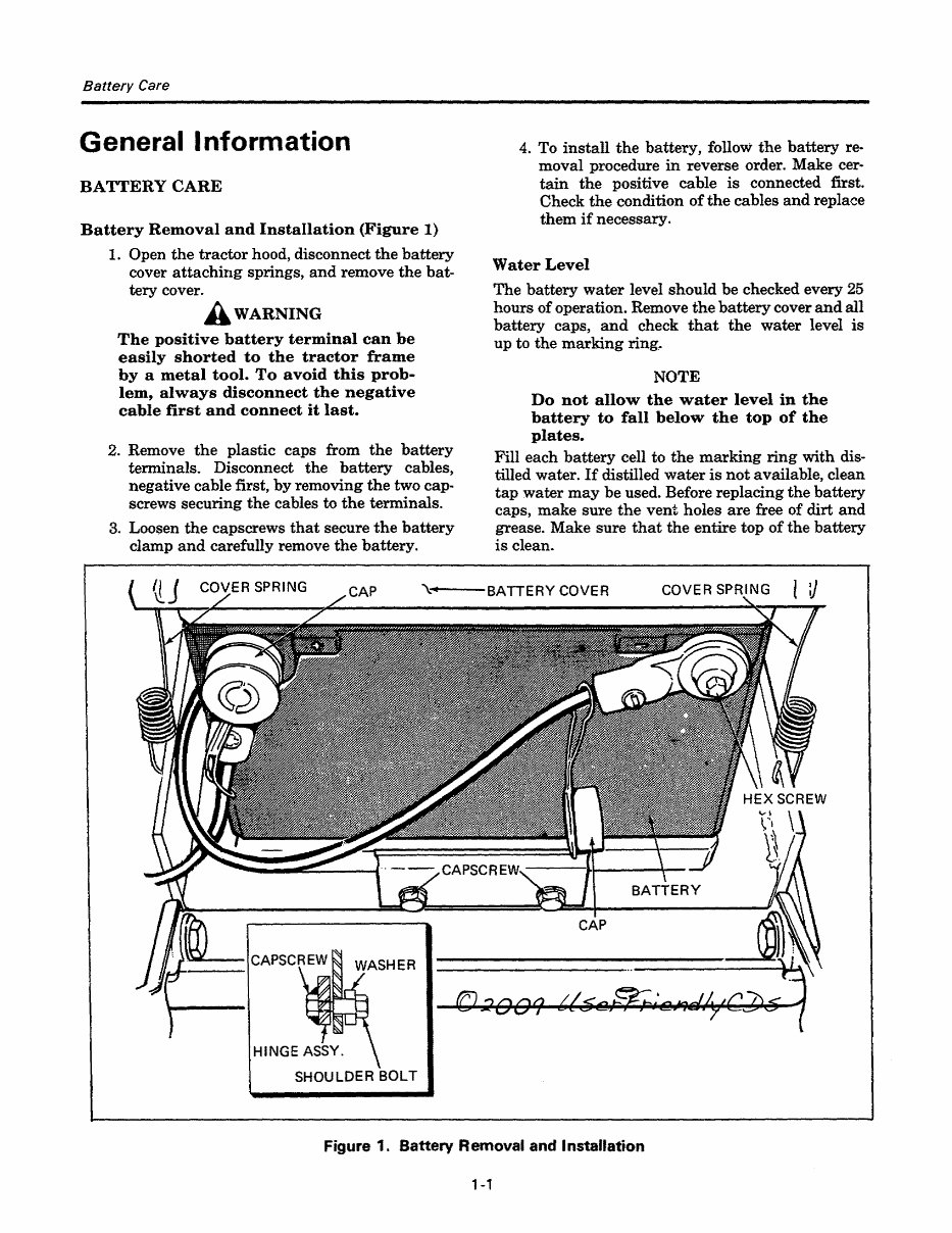
Battery Removal and Installation (Figure 1)
1. Open the tractor hood, disconnect the battery
cover attaching springs, and remove the bat-
tery cover.
A WARNING
The positive battery terminal can be
easily shorted to the tractor frame
by a metal tool. To avoid this prob-
lem, always disconnect the negative
cable first and connect it last.
2. Remove the plastic caps from the battery
terminals. Disconnect the battery cables,
negative cable first, by removing the two cap-
screws securing the cables to the terminals.
3. Loosen the capscrews that secure the battery
clamp and carefully remove the battery.
4. To install the hattery, follow the battery re-
moval procedure in reverse order. Make cer-
tain the positive cable is connected first.
Check the condition of the cables and replace
them if necessary.
Water Level
The battery water level should be checked every 25
hours of operation. Remove the battery cover and all
battery caps, and check that the water level is
up to the marking ring.
NOTE
Do not allow the water level in the
battery to fall below the top of the
plates.
Fill each battery cell to the marking ring with dis-
tilled water. If distilled water is not available, clean
tap water may be used. Before replacing the battery
caps, make sure the vent holes are free of dirt and
grease. Make sure that the entire top of the battery
is clean.
,\:+4 --BATTERY COVER
HINGE ASSY.
SHOULDER BOLT
Figure 1. Battery Removal and Installation
1-1
You're Reading a Preview
What's Included?
Fast Download Speeds
Online & Offline Access
Access PDF Contents & Bookmarks
Full Search Facility
Print one or all pages of your manual
$31.99
Viewed 86 Times Today


Secure transaction
What's Included?
Fast Download Speeds
Online & Offline Access
Access PDF Contents & Bookmarks
Full Search Facility
Print one or all pages of your manual
$31.99
This is an automotive service repair manual in PDF format.
- Contains all the necessary instructions for any vehicle repair
- Used by technicians and mechanics
- Accurate, clear, and concise text with detailed illustrations
- Comprehensive diagrams, in-depth illustrations, and manufacturer's specifications included


