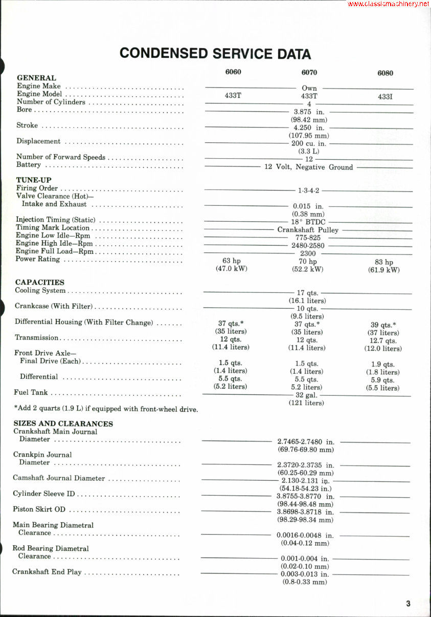
CONDENSED SERVICE DATA GENERAL Engine Make Engine Model Number of Cylinders Bore Stroke Displacement Number of Forward Speeds Battery TUNE-UP Firing Order Valve Clearance (Hot)— Intake and Exhaust Injection Timing (Static) Timing Mark Location Engine Low Idle—Rpm Engine High Idle—Rpm Engine Full Load—Rpm Power Rating CAPACITIES Cooling System Crankcase (With Filter) Differential Housing (With Filter Change) Transmission Front Drive Axle- Final Drive (Each) Differential Fuel Tank *Add 2 quarts (1,9 L) if equipped with front-wheel drive. SIZES AND CLEARANCES Crankshaft Main Journal Diameter Crankpin Journal Diameter Camshaft Journal Diameter Cylinder Sleeve ID Piston Skirt OD Main Bearing Diametral Clearance Rod Bearing Diametral Clearance Crankshaft End Play 6060 433T 6070 Own 433T - 4 - 6080 4331 - 3.875 in. - (98.42 mm) - 4.250 in. - (107,95 mm) - 200 cu. in. - (3.3 L) 12 12 Volt, Negative Ground 63 hp (47.0 kW) 37 qts.* (35 liters) 12 qts. (11.4 liters) 1.5 qts. (1.4 liters) 5.5 qts. (5.2 liters) 1-3-4-2 0.015 in. (0.38 mm) 18° BTDC Crankshaft Pulley 775-825 2480-2580 2300 70 hp (52.2 kW) — 17 qts. — (16.1 liters) — 10 qts. — (9.5 liters) 37 qts.* (35 liters) 12 qts. (11.4 liters) 1.5 qts. (1.4 liters) 5.5 qts. 5.2 liters) — 32 gal. — (121 liters) 2.7465-2.7480 in. (69.76-69.80 mm) 2.3720-2.3735 in. (60.25-60.29 mm) - 2.130-2.131 i^. - (54.18-54.23 in.) 3.8755-3.8770 in. (98.44-98.48 mm) 3.8698-3.8718 in. (98.29-98.34 mm) 0.0016-0.0048 in. (0.04-0.12 mm) 0.001-0.004 in. (0.02-0.10 mm) 0.003-0.013 in. (0.8-0.33 mm) 83 hp (61.9 kW) 39 qts.* (37 liters) 12.7 qts. (12.0 liters) 1.9 qts. (1.8 liters) 5.9 qts. (5.5 liters)
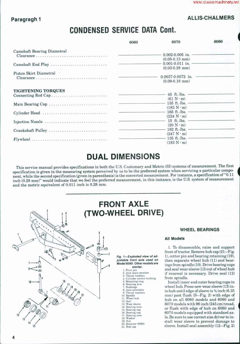
Paragragh 1 ALLIS-CHALMERS CONDENSED SERVICE DATA Cont. 6060 Camshaft Bearing Diametral Clearance Camshaft End Play Piston Skirt Diametral • Clearance TIGHTENING TORQUES Connecting Rod Cap Main Bearing Cap . . . Cylinder Head Injection Nozzle Crankshaft Pulley Flywheel 6070 - 0.002-0.005 in. - (0.05-0.13 mm) - 0.001-0.011 in. - (0.03-0.28 mm) 0.0037-0.0072 in, (0.09-0.18 mm) 6080 45 ft.-lhs. (61 N • m) 135 ft.-lbs. (183 N • m) 165 ft.-lbs. (224 N • m) 15 ft.-lbs. (20 N • m) • 182 ft.-lbs. (247 N • m) - 135 ft.-lbs. (183 N • m) DUAL DIMENSIONS This service manual provides specifications in both the U.S. Customary and Metric (SI) systems of measurement. The first J specification is given in the measuring system perceived by us to be the preferred system when servicing a particular compo- 1 nent, while the second specification (given in parenthesis) is the converted measurement. For instance, a specification of "0.11 ^ inch (0.28 mm)" would indicate that we feel the preferred measurement, in this instance, is the US. system of measurement and the metric equivalent of 0.011 inch is 0.28 mm. FRONT AXLE (TWO-WHEEL DRIVE) Fig. 1—Exploded view of ad- justabie front axle used on Model 6080. Other models are simiiar. 1. Pivot pin 2. Axle main member 3. Thrust washers 4. Cylinder anchor bushing 5. Retaining ring 6. Steering arm 7. Bushings 8. Axle extension 9. Thrust washers 10. Spindle 11. Wheel hub 12. Seal 13. Wear sleeve 14. Bearing 15. Bearing 16. Bearing 17. Bearing 18. Washer 19. Nut 20. Retainer (6080) 21. Huh cap WHEEL BEARINGS All Models 1. Ib disassemble, raise and support front of tractor. Remove hub cap (21—Fig. 1), cotter pin and bearing retaining (19), then separate wheel hub (11) and bear- ings from spindle (10). Drive bearing cups and seal wear sleeve (13) out of wheel hub if renewal is necessary. Drive seal (12) from spindle. Install inner and outer bearing cups in wheel hub. Press new wear sleeve (13) in- to hub until edge of sleeve is V^ inch (6.35 mm) past flush (S—Fig. 2) with edge of hub on all 6080 models and 6060 and 6070 models with 96 inch (245 cm) tread, or flush with edge of hub on 6060 and 6070 models equipped with standard ax- le. Be sure to use correct size driver to in- stall wear sleeve to prevent damage to sleeve. Install seal assembly (12—Fig. 2)
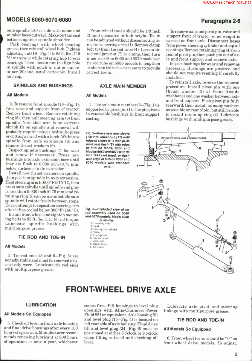
MODELS 6060-6070-6080 Paragraphs 2-6 onto spindle (10) so side with name and number faces outward. Make certain seal bottoms against spindle shoulder. Pack bearings with wheel bearing grease, then reinstall wheel hub. Tighten adjusting nut (19-Fig. 1) to 85 ft.-lb& (115 N ' m) torque while rotating hub to seat bearings. Then, loosen nut to align hole in spindle with notch in nut or nut re- tainer (20) and install cotter pin. Install hub cap. SPINDLES AND BUSHINGS All Models 2. Tb remove front spindle (10—Fig. 1), first raise and support front of tractor. Remove front wheel. Remove retaining ring (5), then pull steering arm (6) from spindle. Note that arm is an extreme shrink fit on spindle and removal will probably require using a hydraulic press or cutting arm off with a torch. Withdraw spindle from axle extension (8) and remove thrust washers (9). Inspect spindle bushings (7) for wear and renew if necessary. Press new bushings into axle extension bore until they are flush to 0.030 inch (0.75 mm) below surface of axle extension. Install new thrust washers on spindle, then position spindle in axle extension. Heat steering arm to 600 °F (315 °C), then press onto spindle until spindle end play is less than 0.030 inch (0.75 mm) and re- taining ring (5) can be installed. Be sure spindle will rotate freely between stops. Do not attempt to reposition steering arm after it has cooled below 300 °F (150 °C). Install front wheel and tighten mount- ing bolts to 85 ft.-lbs. (115 N • m) torque. Lubricate spindle bushings with multipurpose grease. TIE ROD AND TOE-IN All Models 3. Tie rod ends (3 and 6—Fig. 3) are nonadjustable and must be renewed if ex- cessively worn. Lubricate tie rod ends with multipurpose grease. Front wheel toe-in should be 1/8 inch (3 mm) measured at hub height. Tbe-in can be adjusted without disconnecting tie rod from steering arms (1). Remove clamp bolt (5) from tie rod tube (4). Loosen tie rod end jam nut (7) or clamp, then turn inner rod (8) on 6060 and 6070 models or tie rod tube on 6080 models to lengthen or shorten tie rod as necessary to provide correct toe-in. AXLE MAIN MEMBER All Modeis 4. The axle main member (2—Fig. 1) is supported by pivot pin (1). The pin pivots in renewable bushings in front support casting. Fig. 2—Press new wear sleeve (13} into wheel hub (It) untii edgeofsieeveis V* inch (6.35 mm} past flush (S} with edge of hub on Modei 6080 and Modeis 6060 and 6070 with 96 inch (245 cm} tread, or fiush with edge of hub on 6060 and 6070 modeis with standard axie. Tb remove axle and pivot pin, raise and support front of tractor so no weight is carried on front axle. Disconnect hoses from power steering cylinder and cap all openings Remove retaining ring (4) from rear of pivot pin, then push pin out of ax- le and front support and remove axle. Inspect bushings for wear and renew as necessary. Bushings are presized and should not require reaming if carefully installed. Ib reinstall axle, reverse the removal procedure. Install pivot pin with one thrust washer (3) at front (inside wishbone) and one washer between axle and front support. Push pivot pin fully rearward, then install as many washers as possible on rear of pin, but still be able to install retaining ring (4). Lubricate bushings with multipurpose grease. Fig. 3—Expioded view of tie rod assembiy used on 6060 and 6070 modeis. Modei 6080 is simiiar. 1. Steering arm 2. Seal 3. Sliding tie rod end 4. Tube 5. Clamp bolt 6. Tie rod end 7. Jam nut 8. Inner tube a Cylinder FRONT-WHEEL DRIVE AXLE LUBRICATION All Models So Equipped 5. Check oil level in front axle housing and final drive housings after every 100 hours of operation. Manufacturer recom- mends renewing lubricant at 800 hours of operation or once a year, whichever comes first. Fill housings to level plug openings with Allis-Chalmers Power Fluid 821 or equivalent. Axle housing fill and level plug (15—Fig. 4) is located on left rear side of axle housing. Final drive fill and level plug (24—Fig. 6) must be positioned at either 3 o'clock or 9 o'clock when filling with oil and checking oil level. Lubricate axle pivot and steering linkage with multipurpose grease. TIE ROD AND TOE-IN All Modeis So Equipped 6. Front wheel toe-in should be "0" on front-wheel drive models. To adjust,
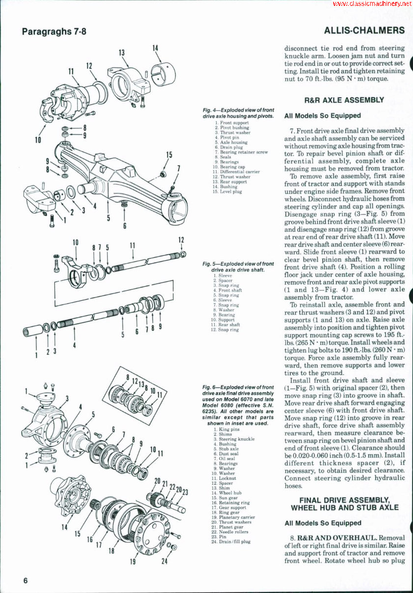
Paragraghs 7-8 ALLIS-CHALMERS 11 12 14 15 Fig. 4—Exploded view of front drive axie housing and pivots. 1. Front support 2. Pivot hushing 3. Thrust washer 4. Pivot pin 5. Axle housing 6. Drain plug 7. Bearing retainer screw 8. Seals 9. Bearings 10. Bearing cap 11. Differential carrier 12. Thrust washer 13. Rear support 14. Bushing 15. Level plug Fig. 5—Exploded view of front drive axle drive shaft. 1. Sleeve 2. Spacer 3. Snap ring 4. Front shaft 5. Snap ring 6. Sleeve 7. Snap ring 8. Washer 9. Bearing 10. Support 11. Rear shaft 12. Snap ring 16 17 Fig. 6—Exploded view of front drive axle final drive assembiy used on Modei 6070 and late Model 6080 (effective S.N. 6235). All other modeis are simiiar except that parts shown in inset are used. 1. King pins 2. Shims 3. Steering knuckle 4. Bushing 5. Stuh axle 6. Dust seal 7. Oil seal 8. Bearings 9. Washer 10. Washer 11. Locknut 12. Spacer 13. Shim 14. Wheel hub 15. Sun gear 16. Retaining ring 17. Gear support 18. Ring gear 19. Planetary carrier 20. Thrust washers 21. Planet gear 22. Needle rollers 23. Pin 24. Drain/fill plug 18 19 24 disconnect tie rod end from steering knuckle arm. Loosen jam nut and turn tie rod end in or out to provide correct set- ting. Install tie rod and tighten retaining nut to 70 ft.-lbs. (95 N • m) torque. R&R AXLE ASSEMBLY All Models So Equipped 7. Front drive axle final drive assembly and axle shaft assembly can be serviced without removing axle housing from trac- tor. To repair bevel pinion shaft or dif- ferential assembly, complete axle housing must be removed from tractor. To remove axle assembly, first raise front of tractor and support with stands under engine side frames. Remove front wheela Disconnect hydraulic hoses from steering cylinder and cap all openings. Disengage snap ring (3—Fig. 5) from groove behind front drive shaft sleeve (1) and disengage snap ring (12) from groove at rear end of rear drive shaft (11). Move rear drive shaft and center sleeve (6) rear- ward. Slide front sleeve (1) rearward to clear bevel pinion shaft, then remove front drive shaft (4). Pbsition a rolling floor jack under center of axle housing, remove front and rear axle pivot supports (1 and 13—Fig. 4) and lower axle assembly from tractor. To reinstall axle, assemble front and rear thrust washers (3 and 12) and pivot supports (1 and 13) on axle. Raise axle assembly into position and tighten pivot support mounting cap screws to 195 ft.- lbs. (265 N • m) torque. Install wheels and tighten lug bolts to 190ft.-lb&(260 N • m) torque. Force axle assembly fully rear- ward, then remove supports and lower tires to the ground. Install front drive shaft and sleeve (1—Fig. 5) with original spacer (2), then move snap ring (3) into groove in shaft. Move rear drive shaft forward engaging center sleeve (6) with front drive shaft. Move snap ring (12) into groove in rear drive shaft, force drive shaft assembly rearward, then measure clearance be- tween snap ring on bevel pinion shaft and end of front sleeve (1). Clearance should be 0.020-0.060 inch (0.5-1.5 mm). Install different thickness spacer (2), if necessary, to obtain desired clearance. Connect steering cylinder hydraulic hoses. FINAL DRIVE ASSEMBLY, WHEEL HUB AND STUB AXLE All Models So Equipped 8. R&R AND OVERHAUL. Removal of left or right final drive is similar. Raise and support front of tractor and remove front wheel. Rotate wheel hub so plug 6
MODELS 6060-6070-6080 (24—Fig. 6) is at the bottom, remove plug and drain oil from final drive. Remove mounting cap screws and separate planetary carrier (19) from wheel hub (14). Remove wheel bearing locknut (11) using a suitable spanner wrench. Withdraw ring gear support (17) with ring gear (18) and bearing cone as an assembly. Thread two M8xl.25 cap screws into tapped holes in ring gear to push bearing cone off support if renewal is necessary. Remove shim (13) and spacer (12) if so equipped. Remove wheel hub assembly (14). Remove cap screws secur- ing stub axle (5) to steering knuckle (3) and remove stub axle. Press planet gear pins (23) outward from planetary carrier (19). Remove planet gears (21) with roller bearings (22) and thrust washers (20). Planet gear thrust washer thickness when new is 0.030-0.033 inch (0.77-0.083 mm). Inspect all hearings for wear, damage or rough operation and renew as necessary Remove seals from stub axle and wheel hub. Inspect bushing (4) in stub axle for wear. Inside diameter of hushing should be 1.656-1.658 inches (42.05-42.13 mm) on Models 6060 and 6070, or 1.774-1.776 inches (45.05-45.13 mm) on Model 6080. Running clearance of axle shaft in bushing is 0.002-0.006 inch (0.05-0.15 mm) on all models. When renewing bushing, press bushing into stub axle until seated against counter- bore. Ream bushing inside diameter to provide desired running clearance. Install new oil seal into stub axle with spring side of seal facing inward. Install dust seal with cupped side outward. Lubricate seal lip, then install stub axle over axle shaft and tighten mounting cap screws to 83 ft.-lbs. (113 N • m) torque. Install new bearing cups, if removed, in- to wheel hub (14). Install new oil seal (7) into wheel hub with spring side of seal facing inward. Be sure seal seats against counterbore. Install dust seal (6) with cup- ped side facing outward. Install wheel hub, bearings and spacer (12) and shim (13), if so equipped, and ring gear support (17) with ring gear (19). Install washers and locknut (11). Adjust wheel bearing preload as follows. On Model 6060 and early Model 6080 (prior to S.N. 6235), tighten locknut (11) to 375 ft.-lbs. (510 N • m) torque while turning wheel hub to make sure bearings remain free. Wrap a string around outer flange of wheel hub and attach a spring scale. Measure wheel hub rolling torque using the spring scale. Specified rolling torque is 10-40 in.-lbs. (1.1-4.5 N • m) which corresponds to spring scale reading of 2-7 pounds (9-31 N) for 6060 or 1.5-5.5 pounds (6.7-24.4 N) for 6080 modela Tb increase rolling torque, install a thinner shim (13). Tb decrease rolling torque, install a thicker shim. On Model 6070 and late Model 6080 (ef fective S.N. 6235), wrap string around outer flange of wheel hub and attach a spring scale. Use the spring scale to measure hub rolling torque while tightening locknut (11). Tighten nut un- til spring scale reading is within range of 2-7 pounds (9-31 N) for Model 6070 or 1.5-5.5 pounds (6.7-24.4 N) for Model 6080. Assemble planetary gears (21) with bearing rollers (22) and thrust washers (20) into planetary carrier. Install planetary pins (23) into carrier and gears. Apply bead of R.T.V. silicone sealer around mounting surface of planetary carrier, then install sun gear (15) and planetary unit on wheel hub. Tighten mounting cap screws to 47 ft.-lbs. (64 N • m) torque. Refill final drive unit to proper level with AUis-Chalmers Power Fluid 821 or equivalent. Install wheel and tire and tighten lug bolts 192 ft.-lba (260 N • m) torque. AXLE SHAFT, STEERiNG KNUCKLE AND KiNG PiNS Ail Models So Equipped 9. R&R AND OVERHAUL. Raise and support front of tractor and remove front wheel. Drain oil from final drive housing and axle housing. Remove final drive assembly as outlined in paragraph 8. Remove axle bearing retaining screw (7—Fig. 4) fron^ axle housing, then pull axle shaft (Fig. 7) with universal joint and bearing from axle housing. Paragraph 9 Remove snap ring (6) and bearing sup- port assembly (8) from axle shaft. Remove snap rings (7), bearing (10) and seals (11 and 12) from bearing support. Seals (13 and 14) are located in stub axle. Disconnect tie rod and steering cylinder (right-hand side) from steering knuckle (3—Fig. 6). Remove king pins (1) and separate steering knuckle from ax- le housing. Examine seals (8—Fig. 4) and bearings (9) for wear or damage and remove from axle housing if renewal is necessary. Ib reinstall, reverse the removal pro- cedure while noting the following special instructions: Install oil seal (11—Fig. 7) with spring side of seal facing bearing (10). Install dust seal (12) with cupped side outward. Install oil seal (14) into stub axle with spring side of seal facing in- ward. Install dust seal (13) with cupped side facing outward. Be sure dust seals contact the oil seals. Lubricate oil seals before installing over axle shaft. NOTE: If axle shafts from both sides have been removed, note that right-hand axle shaft is slightly longer than left-hand shaft. Be sure they are installed in their correct locations. Install axle shaft assembly into axle housing and secure with retaining screw. Make certain retaining screw engages groove in bearing support (8). Install new king pin bearings (9—Fig. 4) and seals (8), if necessary, making cer- tain they are seated in bottom of axle housing bores. Be sure lip of seal is fac- ing inward. Position steering knuckle on end of axle housing and install king pina Fig. 7—Exploded view of front-wheel drive axle shaft assembly. Dust seai (13} and oil seai (14) are located in stub axle. Note thatLH. inner axle shaft is shorter than R. H. inner axie shaft 1. Axle shaft, inner 2. Lock ring 3. Universal joint 4. Yoke 5. Axle shaft, outer 6. Snap ring 7. Snap ring 8. Bearing support 9. "O" ring 10. Bearing 11. Oil seal 12. Dust seal 13. Dust seal 14. Oil seal
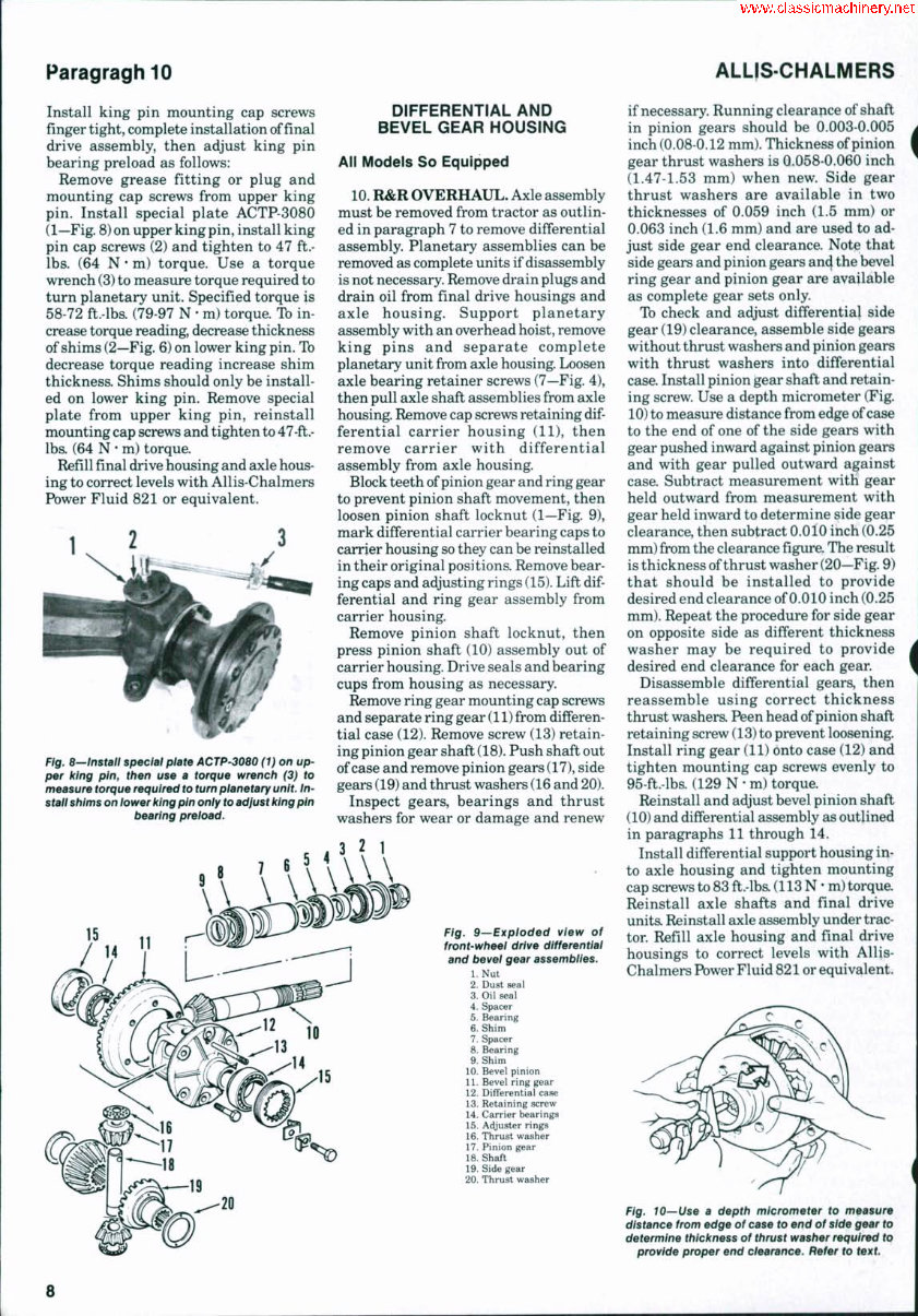
ParagraghiO ALLISCHALMERS Install king pin mounting cap screws finger tight, complete installation of final drive assembly, then adjust king pin bearing preload as follows: Remove grease fitting or plug and mounting cap screws from upper king pin. Install special plate ACTP-3080 (1—Fig. 8) on upper king pin, install king pin cap screws (2) and tighten to 47 ft.- lbs. (64 N • m) torque. Use a torque wrench (3) to measure torque required to turn planetary unit. Specified torque is 58-72 ft.-lbs. (79-97 N • m) torque. To in- crease torque reading, decrease thickness of shims (2—Fig. 6) on lower king pin. Tb decrease torque reading increase shim thickness. Shims should only be install- ed on lower king pin. Remove special plate from upper king pin, reinstall mounting cap screws and tighten to 47-fl.- lbs. (64 N * m) torque. Refill final drive housing and axle hous- ing to correct levels with Allis-Chalmers Power Fluid 821 or equivalent. Fig, 8—'install speciat plate ACTP-3080 (1} on up- per king pin, f/ien use a torque wrench (3) to measure torque required to turn planetary unit, tn- staii shims on iower king pin oniy to adjust king pin bearing preioad. ^7 1 L. DIFFERENTIAL AND BEVEL GEAR HOUSING All Models So Equipped 10. R&R OVERHAUL. Axle assembly must be removed from tractor as outlin- ed in paragraph 7 to remove differential assembly. Planetary assemblies can be removed as complete units if disassembly is not necessary. Remove drain plugs and drain oil from final drive housings and axle housing. Support planetary assembly with an overhead hoist, remove king pins and separate complete planetary unit from axle housing. Loosen axle bearing retainer screws (7—Fig. 4), then pull axle shaft assemblies from axle housing. Remove cap screws retaining dif- ferential carrier housing (11), then remove carrier with differential assembly from axle housing. Block teeth of pinion gear and ring gear to prevent pinion shaft movement, then loosen pinion shaft locknut (1—Fig. 9), mark differential carrier bearing caps to carrier housing so they can be reinstalled in their original positions. Remove bear- ing caps and adjusting rings (15). Lift dif- ferential and ring gear assembly from carrier housing. Remove pinion shaft locknut, then press pinion shaft (10) assembly out of carrier housing. Drive seals and bearing cups from housing as necessary. Remove ring gear mounting cap screws and separate ring gear (11) from differen- tial case (12). Remove screw (13) retain- ing pinion gear shaft (18). Push shaft out of case and remove pinion gears (17), side gears (19) and thrust washers (16 and 20). Inspect gears, bearings and thrust washers for wear or damage and renew 3 ? 1 Fig. 9—Exploded view of front-wheel drive differential and bevei gear assemblies. l.Nut 2. Dust seal 3. Oil seal 4. Spacer 5. Bearing 6. Shim 7. Spacer 8. Bearing 9. Shim 10. Bevel pinion 11. Bevel ring gear 12. Differential case 13. Retaining screw 14. Carrier bearings 15. Adjuster rings 16. Thrust washer 17. Pinion gear 18. Shaft 19. Side gear 20. Thrust washer if necessary. Running clearance of shaft in pinion gears should be 0.003-0.005 inch (0.08-0.12 mm). Thickness of pinion gear thrust washers is G.058-0.060 inch (1.47-1.53 mm) when new. Side gear thrust washers are available in two thicknesses of 0.059 inch (1.5 mm) or 0.063 inch (1.6 mm) and are used to ad- just side gear end clearance. Note that side gears and pinion gears and the bevel ring gear and pinion gear are available as complete gear sets only. Ib check and adjust differential side gear (19) clearance, assemble side gears without thrust washers and pinion gears with thrust washers into differential case. Install pinion gear shaft and retain- ing screw. Use a depth micrometer (Fig. 10) to measure distance from edge of case to the end of one of the side gears with gear pushed inward against pinion gears and with gear pulled outward against case. Subtract measurement with gear held outward from measurement with gear held inward to determine side gear clearance, then subtract O.OIO inch (0.25 mm) from the clearancefigure.The result is thickness of thrust washer (20—Fig. 9) that should be installed to provide desired end clearance of 0.010 inch (0.25 mm). Repeat the procedure for side gear on opposite side as different thickness washer may be required to provide desired end clearance for each gear. Disassemble differential gears, then reassemble using correct thickness thrust washera Peen head of pinion shafl retaining screw (13) to prevent loosening. Install ring gear (11) onto case (12) and tighten mounting cap screws evenly to 95-ft.-lbs. (129 N • m) torque. Reinstall and adjust bevel pinion shaft (10) and differential assembly as outlined in paragraphs 11 through 14. Install differential support housing in- to axle housing and tighten mounting cap screws to 83 ft.-lba (113 N * m) torque. Reinstall axle shafts and final drive unita Reinstall axle assembly under trac- tor. Refill axle housing and final drive housings to correct levels with Allis- Chalmers Power Fluid 821 or equivalent. Fig. 10—Use a depth micrometer to measure distance from edge of case to end of side gear to determine thickness of thrust washer required to provide proper end clearance. Refer to text. 8
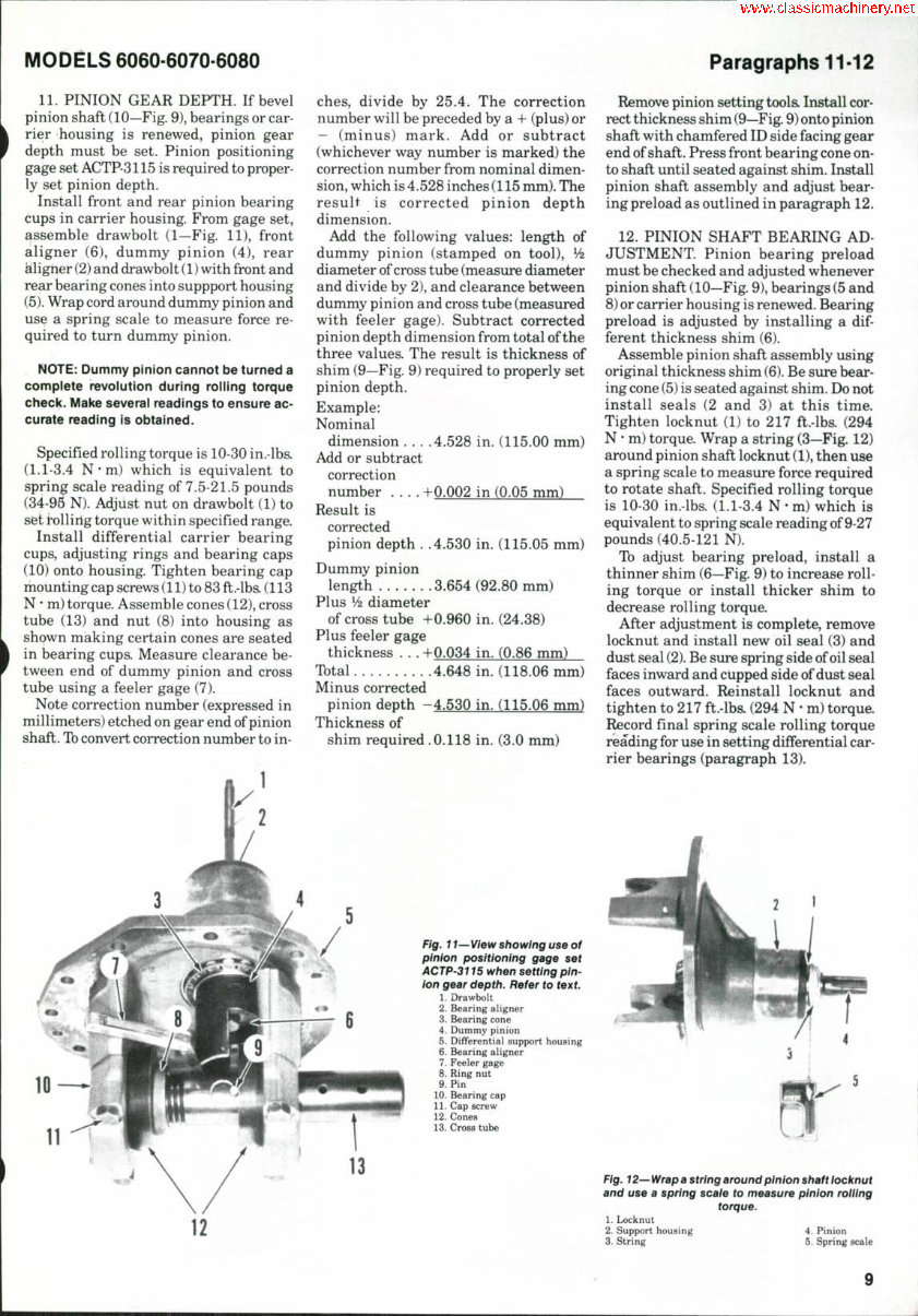
MODELS 6060-6070-6080 Paragraphs 11-12 11. PINION GEAR DEPTH. If bevel pinion shaft (10—Fig. 9), bearings or car- rier housing is renewed, pinion gear depth must be set. Pinion positioning gage set ACTP-3115 is required to proper- ly set pinion depth. Install front and rear pinion bearing cups in carrier housing. From gage set, assemble drawbolt (1—Fig. 11), front aligner (6), dummy pinion (4), rear aligner (2) and drawbolt (1) with front and rear bearing cones into suppport housing (5). Wrap cord around dummy pinion and use a spring scale to measure force re- quired to turn dummy pinion. NOTE: Dummy pinion cannot be turned a complete revolution during rolling torque check. Make several readings to ensure ac- curate reading is obtained. Specified rolling torque is 10-30 in.-lbs. (1.1-3.4 N ' m) which is equivalent to spring scale reading of 7.5-21.5 pounds (34-96 N). Adjust nut on drawbolt (1) to set tollirlg torque within specified range. Install differential carrier bearing cups, adjusting rings and bearing caps (10) onto housing. Tighten bearing cap mounting cap screws (11) to 83 fl.-lb& (113 N • m) torque. Assemble cones (12), cross tube (13) and nut (8) into housing as shown making certain cones are seated in bearing cups. Measure clearance be- tween end of dummy pinion and cross tube using a feeler gage (7). Note correction number (expressed in millimeters) etched on gear end of pinion shaft. Tb convert correction number to in- ches, divide by 25.4. The correction number will be preceded by a + (plus) or - (minus) mark. Add or subtract (whichever way number is marked) the correction number from nominal dimen- sion, which is 4.528 inches (115 mm). The result is corrected pinion depth dimension. Add the following values: length of dummy pinion (stamped on tool), ^ diameter of cross tube (measure diameter and divide by 2), and clearance between dummy pinion and cross tube (measured with feeler gage). Subtract corrected pinion depth dimension from total of the three values. The result is thickness of shim (9—Fig. 9) required to properly set pinion depth. Example: Nominal dimension . . . .4,528 in. (115.00 mm) Add or subtract correction number , . . . +0.002 in (0.05 mm) Result is corrected pinion depth , .4,530 in. (115.05 mm) Dummy pinion length 3.654 (92.80 mm) Plus V2 diameter of cross tube +0.960 in. (24.38) Plus feeler gage thickness ., , +0.034 in. (0.86 mm) Total 4,648 in. (118,06 mm) Minus corrected pinion depth —4,530 in. (115.06 mm) Thickness of shim required ,0.118 in. (3.0 mm) Fig. 11—View showing use of pinion positioning gage set ACTP-3i 15 when setting pin- ion gear depth. Refer to text. 1. Drawbolt 2. Bearing aligner 3. Bearing cone 4. Dummy pinion 5. Differential support housing 6. Bearing aligner 7. Feeler gage 8. Ring nut 9. Pin 10. Bearing cap 11. Cap screw 12. Cones 13. Cross tube Remove pinion setting toola Install cor- rect thickness shim (9—Fig. 9) onto pinion shaft with chamfered ID side facing gear end of shaft. Press front bearing cone on- to shaft until seated against shim. Install pinion shaft assembly and adjust bear- ing preload as outlined in paragraph 12. 12. PINION SHAFT BEARING AD- JUSTMENT. Pinion bearing preload must be checked and adjusted whenever pinion shaft (10—Fig. 9), bearings (5 and 8) or carrier housing is renewed. Bearing preload is adjusted by installing a dif- ferent thickness shim (6). Assemble pinion shaft assembly using original thickness shim (6). Be sure bear- ing cone (5) is seated against shim. Do not install seals (2 and 3) at this time. Tighten locknut (1) to 217 fl.-lba (294 N • m) torque. Wrap a string (3—Fig. 12) around pinion shaft locknut (1), then use a spring scale to measure force required to rotate shaft. Specified rolling torque is 10-30 in.-lbs, (1.1-3,4 N • m) which is equivalent to spring scale reading of 9-27 pounds (40.5-121 N). Tb adjust bearing preload, install a thinner shim (6—Fig, 9) to increase roll- ing torque or install thicker shim to decrease rolling torque. After adjustment is complete, remove locknut and install new oil seal (3) and dust seal (2). Be sure spring side of oil seal faces inward and cupped side of dust seal faces outward. Reinstall locknut and tighten to 217 ft.-lbs. (294 N • m) torque. Record final spring scale rolling torque reading for use in setting differential car- rier bearings (paragraph 13), 13 Fig. 12—Wrap a string around pinion shaft iocknut and use a spring sca/e to measure pinion roiiing torque. 1. Locknut 2. Support housing 4. Pinion 3. String 5. Spring scale 9
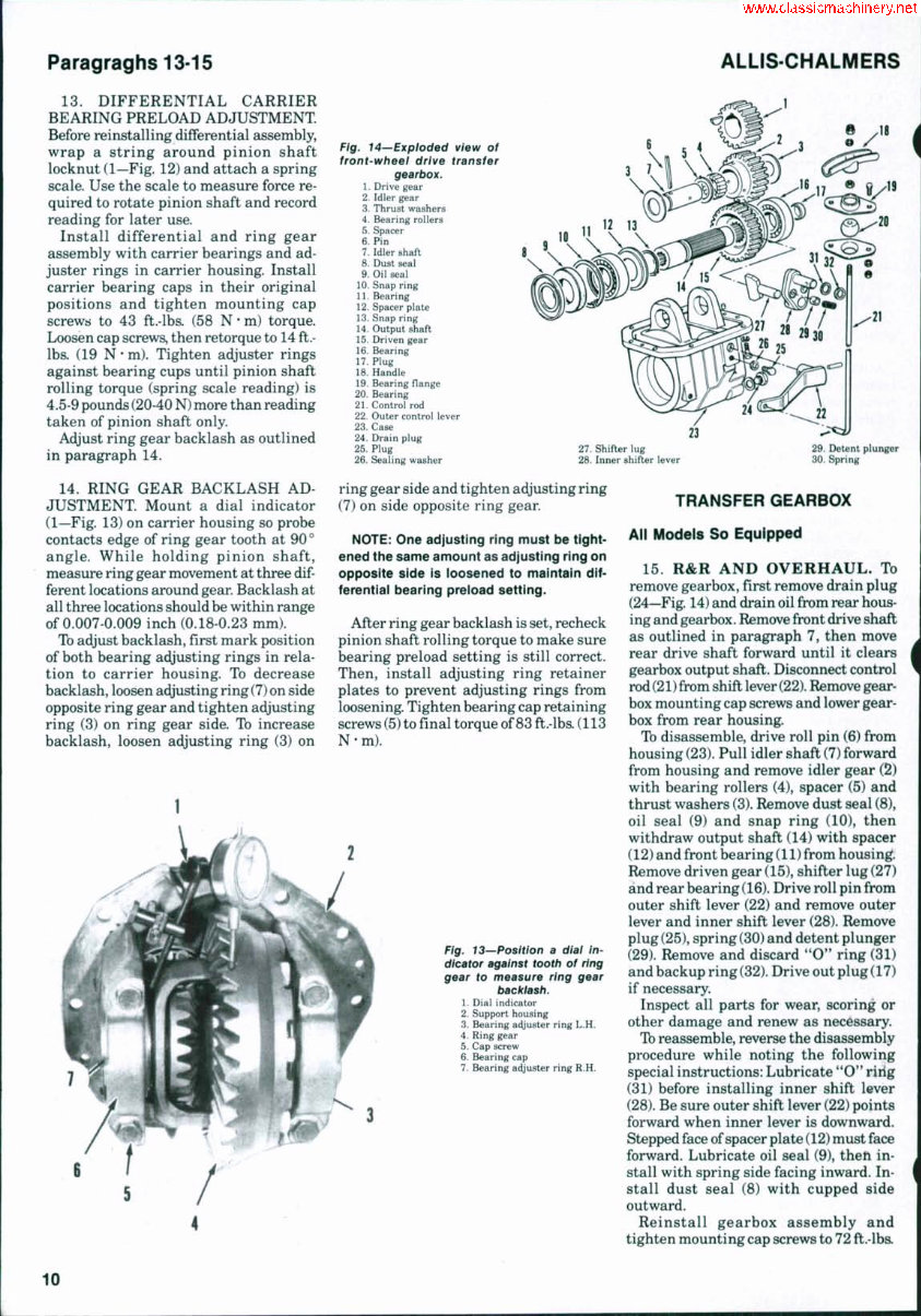
Paragraghs 13-15 ALLIS-CHALMERS 13. DIFFERENTIAL CARRIER BEARING PRELOAD ADJUSTMENT Before reinstalling differential assembly, wrap a string around pinion shaft locknut (1—Fig. 12) and attach a spring scale. Use the scale to measure force re- quired to rotate pinion shaft and record reading for later use. Install differential and ring gear assembly with carrier bearings and ad- juster rings in carrier housing. Install carrier bearing caps in their original positions and tighten mounting cap screws to 43 ft.-lbs. (58 N • m) torque. Loosen cap screws, then retorque to 14 ft.- lbs. (19 N • m). Tighten adjuster rings against bearing cups until pinion shaft rolling torque (spring scale reading) is 4.5-9 pounds (20-40 N) more than reading taken of pinion shaft only. Adjust ring gear backlash as outlined in paragraph 14. 14. RING GEAR BACKLASH AD- JUSTMENT. Mount a dial indicator (1—Fig. 13) on carrier housing so probe contacts edge of ring gear tooth at 90° angle. While holding pinion shaft, measure ring gear movement at three dif- ferent locations around gear. Backlash at all three locations should be within range of 0.007-0.009 inch (0.18-0.23 mm). Tb adjust backlash, first mark position of both bearing adjusting rings in rela- tion to carrier housing. To decrease backlash, loosen adjusting ring (7) on side opposite ring gear and tighten adjusting ring (3) on ring gear side. To increase backlash, loosen adjusting ring (3) on Fig. 14—Expioded view of front-wheei drive transfer gearbox, 1. Drive gear 2. Idler gear 3. Thrust washers 4. Bearing rollers 5. Spacer 6. Pin 7. Idler shaft 8. Dust seal 9. Oil seal 10. Snap ring 11. Bearing 12. Spacer plate 13. Snap ring 14. Output shaft 15. Driven gear 16. Bearing 17. Plug 18. Handle 19. Bearing flange 20. Bearing 21. Control rod 22. Outer control lever 23. Case 24. Drain plug 25. Plug 26. Sealing washer 27. Shifter lug 28. Inner shifter lever 29. Detent plunger 30. Spring ring gear side and tighten adjusting ring (7) on side opposite ring gear. NOTE: One adjusting ring must be tight- ened the same amount as adjusting ring on opposite side is ioosened to maintain dif- ferential bearing preioad setting. After ring gear backlash is set, recheck pinion shaft rolling torque to make sure bearing preload setting is still correct. Then, install adjusting ring retainer plates to prevent adjusting rings from loosening. Tighten bearing cap retaining screws (5) to final torque of 83 ft.-lbs. (113 N-m). Fig. 13~'Position a diai in- dicator against tooth of ring gear to measure ring gear backlash. 1. Dial indicator 2. Support housing 3. Bearing adjuster ring L.H. 4. Ring gear 5. Cap screw 6. Bearing cap 7. Bearing adjuster ring R.H. TRANSFER GEARBOX All Models So Equipped 15. R&R AND OVERHAUL. To remove gearbox, first remove drain plug (24—Fig. 14) and drain oil from rear hous- ing and gearbox. Remove front drive shaft as outlined in paragraph 7, then move rear drive shaft forward until it clears gearbox output shaft. Disconnect control rod (21) from shift lever (22). Remove gear- box mounting cap screws and lower gear- box from rear housing. To disassemble, drive roll pin (6) from housing (23). Pull idler shaft (7) forward from housing and remove idler gear (2) with bearing rollers (4), spacer (5) and thrust washers (3), Remove dust seal (8), oil seal (9) and snap ring (10), then withdraw output shaft (14) with spacer (12) and front bearing (11) from housing. Remove driven gear (15), shifter lug (27) and rear bearing (16). Drive roll pin from outer shift lever (22) and remove outer lever and inner shift lever (28). Remove plug (25), spring (30) and detent plunger (29). Remove and discard "O" ring (31) and backup ring (32). Drive out plug (17) if necessary. Inspect all parts for wear, scoring or other damage and renew as necessary. Tb reassemble, reverse the disassembly procedure while noting the following special instructions: Lubricate "O" ririg (31) before installing inner shift lever (28). Be sure outer shift lever (22) points forward when inner lever is downward. Stepped face of spacer plate (12) must face forward. Lubricate oil seal (9), theft in- stall with spring side facing inward. In- stall dust seal (8) with cupped side outward. Reinstall gearbox assembly and tighten mounting cap screws to 72 ft.-lba 10
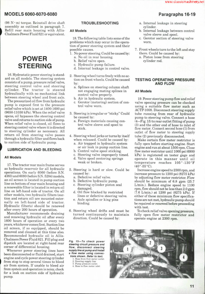
MODELS 6060-6070-6080 Paragraphs 16-19 (98 N • m) torque. Reinstall drive shaft assembly as outlined in paragraph 7. Refill rear main housing with Allis- Chalmers Power Fluid 821 or equivalent. POWER STEERING 16. Hydrostatic power steering is stand- ard on all models. The steering system consists of a pump, pressure relief valve, steering control valve and steering cylinder. The tractor is steered hydraulically with no mechanical link between steering wheel and front axle. The pressurized oil flow from hydraulic pump is exposed first to the pressure relief valve which is set at 1400-1600 psi (9650-11030 kPa). When the relief valve opens, oil bypasses the steering control valve and returns to suction side of pump. When relief valve is closed, oil flows to steering control valve where it is directed to steering cylinder as necessary. All return oil from steering valve passes through a hydraulic filter and flows back to suction side of hydraulic pump. LUBRICATION AND BLEEDING Ali Models 17. The tractor rear main frame serves as hydraulic reservoir for all hydraulic operations. On early 6060 (before S.N. 4383) and 6080 (before S.N. 5284) models, an oil screen is located in pump suction line on bottom of rear main housing and a renewable filter is located in return oil line on left-hand side of tractor. On all other models, two hydraulic filters (suc- tion and return oil) are mounted exter- nally on left-hand side of tractor. Hydraulic filter(s) should be renewed after every 200 hours of operation. Manufacturer recommends draining and renewing hydraulic oil after every 1600 hours of operation or every two years, whichever comes first. Suction line oil screen, if so equipped, should be removed and cleaned at this time also. Recommended hydraulic oil is Allis- Chalmers Power Fluid 821. Fill plug and dipstick are located at right-hand rear corner of differential housing. Whenever power steering lines have been disconnected or fiuid drained, start engine and cycle power steering cylinder from stop to stop several times to bleed air from system. If unable to bleed air from system and operation is noisy, check for a leak on suction side of hydraulic pump. TROUBLESHOOTING Ail Modeis 18. The following table lists some of the problems which may occur in the opera- tion of power steering system and their possible causes. 1. No power steering. Could be caused by: a. No oil in rear housing. b. Relief valve open. c. Hydraulic pump failure. d. Internal leakage in control valve. 2. Steering wheel turns freely with no ac- tion on front wheels. Could be caused by: a. Splines on steering column shaft not engaging mating splines in control valve properly. b. Air in hydraulic system. c. Gerotor (metering) section of con- trol valve worn. 3. Steering is irregular or "sticky." Could be caused by: a. Foreign materials causing con- trol valve sleeve and spool to stick. 4. Steering wheel jerks or turns by itself when released. Could be caused by: a. Air trapped in hydraulic system or air leak in pump suction line. b. Control valve spool sticking. c. Steering valve improperly timed. d. Valve spool centering springs weak or broken. 5. Steering is hard or slow. Could be caused by: a. Defective relief valve. b. Defective hydraulic pump. c. Steering cylinder piston seal damaged. d. Oil flow blocked by restricted lines or defective steering valve. e. Axle spindles or king pins binding. 6. Steering wheel drifts and must be turned continuously to maintain direction. Could be caused by: a. Internal leakage in steering cylinder. b. Internal leakage between control valve sleeve and spool. c. Gerotor section of steering valve worn. 7. Front wheels turn to the left and stay there. Could be caused by: a. Piston loose from steering cylinder rod. TESTING OPERATING PRESSURE AND FLOW Ail Modeis 19. Power steering pump flow and relief valve opening pressure can be checked using a suitable flow meter such as ACTP-1008. Disconnect steering supply tube running from rear of hydraulic pump to steering valve. Connect a hose (4—Fig. 15) to rear outlet fitting of pump (3) and the other end of hose to inlet of flow meter. Connect second hose (1) from outlet of flow meter to steering supply tube (2) previously disconnected. Make certain flow meter restrictor is fully open before starting engine. Start engine and run at about 1500 rpm. Close flow meter restrictor until 1000 psi (6900 kPa) is registered on tester gage and operate in this manner until oil temperature reaches 105°-130 °F (40°-55°C). Increase engine speed to 2300 rpm, and increase pressure to 1200 psi (8275 kPa) by adjusting flow meter restrictor. Flow should be minimum of 6.8 gpm (25.7 L/min.). Reduce engine speed to 1100 rpm,flowshould not be less than 2.0 gpm (7.6 L/min.) at 1200 psi (8275 kPa). If either of these minimum flow specifica- tions are not met, hydraulic pump should be repaired or renewed before proceeding with test. Tb check relief valve opening pressure, fully open flow meter restrictor and operate engine at 2300 rpm. Fig. 15—To check power steering circuit pressure and fiow, disconnect steering supply ilne at pump and instaii a fiow meter using connec- tions shown. Refer to text. 1. Hose from flow meter outlet 2. Steering supply line 3. Pump pressure outlet 4. Hose to flow meter inlet 11
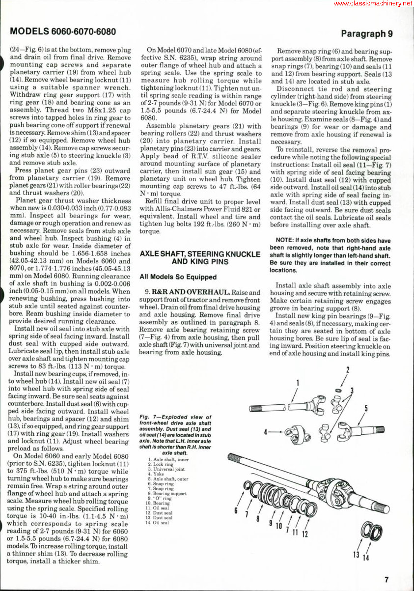
Allis Chalmers 6060/6070/6080 Tractor Service & Repair Manual
Models covered:
Allis Chalmers 6060
Allis Chalmers 6070
Allis Chalmers 6080
The Allis Chalmers 6060/6070/6080 Tractor Service & Repair Manual is an essential resource for maintaining and repairing these tractor models. Developed by Allis Chalmers, this manual provides detailed instructions and precise specifications to ensure accurate maintenance and effective troubleshooting.
Inside, you'll find comprehensive procedures for routine maintenance tasks such as oil changes, filter replacements, and brake inspections. The manual also covers more complex repairs, including engine diagnostics, transmission servicing, and hydraulic system troubleshooting. Detailed diagrams and illustrations facilitate the identification and repair of components, ensuring each task is performed correctly and efficiently.
Designed for professional technicians and experienced DIY enthusiasts, this manual delivers the technical information needed to keep your Allis Chalmers 6060, 6070, and 6080 tractors running smoothly. By following the detailed guidance provided, you can ensure long-term reliability and optimal performance, maximizing the operational lifespan of your equipment.
Format: PDF Compatibility: Compatible with various electronic devices such as PC, Mac, smartphones, and tablets. Requirements: Adobe Reader (free)
Recently Viewed
5,521,897Happy Clients
2,594,462eManuals
1,120,453Trusted Sellers
15Years in Business
Price:
Actual Price:
Allis Chalmers 6060/6070/6080 Tractor OEM Service & Repair Manual