Allis Chalmers 160 Tractor Shop Service Repair Manual - INSTANT
What's Included?
Lifetime Access
Fast Download Speeds
Online & Offline Access
Access PDF Contents & Bookmarks
Full Search Facility
Print one or all pages of your manual
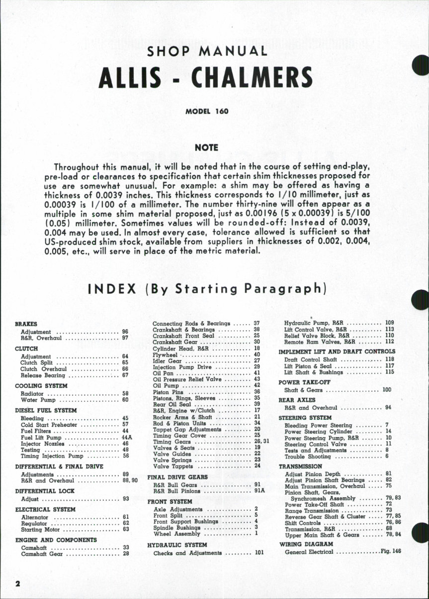
SHOP MANUAL ALLIS - CHALMERS MODEL 160 NOTE Throughout this manual, it will be noted that in the course of setting end-play, pre-load or clearances to specification that certain shim thicknesses proposed for use are somewhat unusual. For example: a shim may be offered as having a thickness of 0.0039 inches. This thickness corresponds to I/IO millimeter, just as 0.00039 is I/IOO of a millimeter. The number thirty-nine will often appear as a multiple in some shim material proposed, just as 0.00196 (5x0.00039) is 5/100 (0.05) millimeter. Sometimes values will be rounded-off: Instead of 0.0039, 0.004 may be used. In almost every case, tolerance allowed is sufficient so that US-produced shim stock, available from suppliers in thicknesses of 0.002, 0.004, 0.005, etc., will serve in place of the metric material. INDEX (By Starting Paragraph) BRAKES Adjustment 96 R&R, Overhaul 97 CLUTCH Adjustment 64 Clutch Split 65 Clutch Overhaul 66 Release Bearing 67 COOLING SYSTEM Radiator 56 Water Pump 60 DIESEL FUEL SYSTEM Bleeding 45 Cold Start Preheater 57 Fuel Filters 44 Fuel Lift Pump 44A Injector Nozzles 46 Testing 46 Timing Injection Pump 56 DIFFERENTIAL & FINAL DRIVE Adjustments 89 R&R and Overhaul 86.90 DIFFERENTIAL LOCK Adjust 93 ELECTRICAL SYSTEM Alternator 61 Regulator 62 Starting Motor 63 ENGINE AND COMPONENTS Camshaft 33 Camshaft Gear 26 Connecting Rods & Bearings 37 Crankshaft & Bearings 36 Crankshaft Front Seal 25 Crankshaft Gear 30 Cylinder Head, R&R 16 Flywheel • 40 Idler Gear 27 Injection Pump Drive 29 Oil Pan 41 Oil Pressure Relief Valve 43 Oil Pump 42 Piston Pins 36 Pistons. Rings. Sleeves 35 Rear Oil Seal 39 R&R. Engine w/Clutch 17 Rocker Arms & Shaft 21 Rod & Piston Units 34 Tappet Gap Adjustments 20 Timing Gear Cover 25 Timing Gears 26.31 Valves & Seats 19 Valve Guides 22 Valve Springs 23 Valve Tappets 24 FINAL DRIVE GEARS R&R Bull Gears 91 R&R Bull Pinions 91A FRONT SYSTEM Axle Adjustments 2 Front Split 5 Front Support Bushings 4 Spindle Bushings 3 Wheel Assembly 1 HYDRAULIC SYSTEM Checks and Adjustments 101 Hydraulic Pump. R&R 109 Lift Control Valve. R&R 113 Relief Valve Block. R&R 110 Remote Ram Valves. R&R 112 IMPLEMENT LIFT AND DRAFT CONTROLS Draft Control Shaft 118 Lift Piston & Seal 117 Lift Shaft & Bushings 115 POWER TAKE-OFF Shaft & Gears 100 REAR AXLES R&R and Overhaul 94 STEERING SYSTEM Bleeding Power Steering 7 Power Steering Cylinder 14 Power Steering Pump. R&R 10 Steering Control Valve 11 Tests and Adjustments 8 Trouble Shooting 6 TRANSMISSION Adjust Pinion Depth 81 Adjust Pinion Shaft Bearings 62 Main Transmission. Overhaul 75 Pinion Shaft, Gears. Synchromesh Assembly 79. 83 Power Take-Off Shaft 72 Range Transmission 73 Reverse Gear Shaft & Cluster 77,85 Shift Controls 76. 66 Transmission. R&R 68 Upper Main Shaft & Gears 78. 84 WIRING DIAGRAM General Electrical Fig. 146
MODEL 160 Paragraphs 1-4 CONDENSED SERVICE DATA GENERAL: Tractor Model 160 Engine Make Perkins Engine Model AD 3.152 Cylinders 3 Bore, inches 3.6 Stroke, inches 5.0 Dispiacement, Cubic Inches 152.7 Conipression Ratio 18.5 :1 Pistons removed from? Above Cylinder sleeves Dry Main Bearings, Number of 4 Alternator, make Delco-Remy Starter, make Delco-Remy Fuel Injection Pump, make CAV Injection Nozzle, make CAV Battery 12V, Neg. Grnd. Forward Speeds 10 Reverse Speeds 2 Fuses, lights & instruments 20 Amp TUNE-UP Firing Order 1-2-3 Valve Tappet Gap, Intake 0.010 Hot, 0.012 Cold Valve Tappet Gap, Exhaust 0.010 Hot, 0.012 Cold Intake Valve Face Angle 45® Exhaust Valve Face Angle 45® Low Idle RPM 725-775 High Idle RPM 2425-2475 Rated Speed RPM 2250 PTO RPM at 2160 Engine RPM 540 Injection Timing (Static) 24® BTDC Timing Mark Location See text Injector Opening Pressure (New) 2750 PSI Injector Opening Pressure (Used) .. 2500 PSI Spray Hoie Diameter 0.0098 SIZES-CAPACIiriES>CLEARANCES: Crankshaft Journal Diameter 2.7485-2.749 Crankpin Diamet€r 2.2485-2.249 Piston Pin Diameter 1.2497-1.250 Valve Stem Diamoter 0.311 -0.312 Camshaft Journal Diameters: No. 1 1.869-1.870 No. 2 1.859-1.860 No. 3 1.839-1.840 Piston Ring Specifications See Text, Para. 35 Connecting Rod Eiearing Clearance 0.0025-0.004 Main Bearing Clearance 0.0025-0.004 Crankshaft End Play 0.002-0.015 Cooling System Capacity 8 Qts. (US) Crankcase Capacity 6 Qts. (US) Crankcase Capacity (With Fiiter) .... 6.5 Qts. (US) Fuel Tank 13.5 Gals. (US) Transmission, Final Drive & Hydraulic System 29 Qts. (US) TORQUE VALUES-TIGHTENING TENSION Cylinder Head Nuts 55-60 Ft.-Lbs. Connecting Rod Nuts (plain) 65-70 Ft.-Lbs. Connecting Rod Nuts (cadmium-plated) .. 45-50 Ft.-Lbs. Main Bearing Cap Screws 110-115 Ft.-Lbs. Fiywheel Cap Screws 75 Ft.-Lbs. Atomizer (injector) Holding Nuts 10-12 Ft.-Lbs. FRONT SYSTEM 7 8 9 10 11 12 Fig. 1 — Expioded view, spindie and wheel hub. 10. 11. 12. Spindle assembly Thrust washers Snap ring Kit, seal wear Inner bearing cone Inner bearing cup Hub assembly Outer bearing cup Outer bearing cone Washer " Wheel nut Cap 1. WHEEL ASSEMBLY. Conven- tional steel disc wheels are reversible on hubs. Wheel bearings should be cleaned and repacked with No. 2 wheel bearing grease after each 500 hours operation. To adjust, tighten axle spindle nut until a distinct drag is felt, loosen nut one castellation and install new pin. Always renew seal assembly (4—Fig. 1) when bearings are repacked. 2. AXLE ADJUSTMENTS. Front wheel tread is adjustable from 52 to 72 inches in 4 inch increments with the wheels dished in and from 57 to 77 inches with the wheels dished out. L&R tie rod extensions (10—Fig. 2) are grooved at 2-inch intervals to correspond to hole spacing in spindle support bars (14) for ease in realign- ment; however, it is advisable to check and reset toe-in at i^ to Vs- inch whenever front wheel tread is changed. Adjust at tie rod end (11) when required. 3. SPINDLE BUSHINGS. With trac- tor front supported, remove front wheels, snap ring (3—Fig. 1), steering arm (13—Fig. 2) and Woodruff key. Spindle can then be pushed down in support tube and removed. Drive bushings (15) from tube bore and drive or press in new bushings until flush with tube ends. Spindle bushings are furnished pre-sized and reaming is not normally required. Reinstall thrust washers (2—Fig. 1) on spindle and reassemble. A single grease fit- ting, located at a midpoint of the spindle support tube, eliminates the need for aligning bushings with lube ports. 4. FRONT SUPPORT BUSHINGS. Axle pivot pin bushings (5—Fig. 2) are renewable. New bushings are pre- sized and require no reaming. Defec- tive bushings may be pressed or driven from support (4) when front axle is removed.
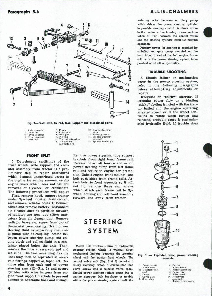
Paragraphs 5-6 Rg. 2—Front axle, tie rod, front support and associated parts. 1. Axle as9enilil>' 1. lUvot bolt ;{. I'lvot bear I UK A. Front support Plugs Pivot pin Roll pin Tie rod TJe rod exteiiHion Tie rod end radjustable> l:!. l*ower steering ram i:t. HteeriiiK arms H, Spindle support assembly lTi. Spindle bushiims rRONT SPLIT 5. Detachment (splitting) of the front wheels, axle support and radi- ator assembly from tractor is a pre- liminary step to repair procedures which demand unrestricted access to the engine for engine removal or for engine work which does not call for removal of flywheel or crankshaft. The following procedures will apply: First, remove hood, support tractor under flywheel housing, drain coolant and remove radiator hoses. Disconnect cables and remove battery. Disconnect air cleaner duct at partition forward of radiator and flex tube (filter indi- cator) from air cleaner duct. Remove radiator brace cap screw from top of thermostat cover casting. Drain power steering fluid by separating reservoir to pump tube at coupling located be- tween power steering pump and en- gine block and collect fluid in a con- tainer placed below the axle. Then, remove the tube at reservoir end and set aside. The two remaining flexible lines may then be separated at reser- voir fittings, capped or taped off. Re- move pins from each end of power steering ram (12—Fig. 2) and secure cylinder with wire hangers from en- gine front support brackets to prevent damage to hydraulic lines and fittings. Remove power steering tube support brackets from right hand frame rail. Release drive belt tension and unbolt power steering pump from left frame rail and secure to engine for protec- tion. Unbolt engine front mounts (one bolt each side) from frame rails. At- tach hoist to front assembly so it will not tip, remove three cap screws which attach each frame rail to fly- wheel housing and roll front assembly forward and away from tractor. STEERING SYSTEM Model 160 tractors utilize a hydrostatic steering system which is without direct mechanical linkage between the steering wheel and the tractor front wheels. The control valve unit (Fig. 5 & 6) contains a rotary metering motor, a commutator feed valve sleeve and a selector valve spool. Should power steering failure occur due to engine stoppage, belt breakage or trouble within the power steering system itself, the ALLIS-CHALMERS metering motor becomes a rotary pump which drives the power steering cylinder to provide steering control. A check valve in the control valve housing allows recircu- lotion of flmd between the control valve and the steering cylinder (ram) for manual operation. Primary power for steering is supplied by a belt-driven gear pump mounted on the front inboard end of the left engine frame rail, with the power steering system inde- pendent of all other hydraulics. TROUBLE SHOOTING 6. Should failure or malfunction occur in the power steering system, refer to the following paragraphs before attempting adjustments or repairs. Irregular or "Sticky'' steering. If irregular power flow or a binding "sticky** feeling is noted with the trac- tor halted and the engine operating at rated speed, or, if the wheel con- tinues to rotate when turned and released, probable cause is contamin- ated hydraulic fluid. If trouble does 4 11 Fig. 3 — Exploded view, power steering reservoir. 1. Cover screw vv/washer 2. Dipstick, inch seal 3. Cover 4. Cover seal 5. Snap ring U. Spring, w/vvashers 7. Filter assembly 8. Snap ring 9. Filter seal 10. Reservoir assembly XI. Tube fitting seals
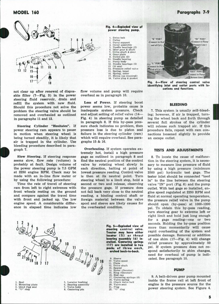
MODEL 160 Paragraphs 7-9 Fig. 4—Expioded view of power sfeering pump. 10. 11. 12. 13 14. 15. 16. 17. 18. Drive belt Pulley Pump support Cover assembly Needle bearings (2) Idler gear & shaft Drive shaft & gear Gear plate Dowel pin (2) Needle bearing Pump body Needle bearings (2) Oil seal Pressure relief vaive Spring, inner Spring, outer Shims (as required) Valve plug & gasket not clear up after renewal of dispos- able filter (7—Fig. 3) in the power steering fluid reservoir, drain and refill the system with new fluid. Should this procedure not solve the problem the steering valve should be removed and overhauled as outlined in paragraphs 11 and 12. Steering Cylinder "Hesitates". If power steering ram appears to pause in motion when steering wheel is being turned steadily, it is likely that air is trapped in the cylinder. Use bleeding procedure described in para- graph 7. Slow Steering. If steering response seems slow, flow rate (volume) is probably at fault. Design volume of the power steering pump is 7.5 GPM at 2250 engine RPM. Check may be made with an in-line flow meter or by using the following procedure: Time the rate of travel of steering ram from left to right extremes with front wheels resting on the ground and compare against the travel time with front end jacked up. Use low engine speed. A considerable differ- ence in elapsed time indicates low • 1. Seal 2. Mounting plate 3. Quad rlQg seal 4. "O" ring 5. Locator bushing C. Bearing assembly 7, Valve body 8. Centering pin flow volume and pump will require overhaul as in paragraph 10. Loss of Power. If steering boost power seems low, probable cause is inadequate system pressure. Check and adjust setting of relief valve (14— Fig. 4) in steering pump as detailed in paragraph 8. If this by-pass pres- sure check indicates no problem, then pressure loss is due to piston seal failure in the steering cylinder (ram) which will require overhaul. See para- graphs 15 & 16. Overheating. If system operates ex- tremely hot, install a high pressure gage as outlined in paragraph 8 and find the neutral position of the control valve by rotating wheel slowly in each direction, halting at point of lowest pressure reading. Control valve is then at its neutral point. Turn steering wheel to a limit stop, hold a second or two and release, observing the pressure gage. If pressure does not fall back very close to the neutral reading, a binding control shaft or foreign material between the valve spool and sleeve are likely causes for the overheated condition. Fig. 5—Exploded view of steering control valve. Troctor may have either locator (5) or thrust bearing assembiy (6) in- stalled. Centering springs (17) are installed in two packs of three each, arched baci(-to-bacit. 9. Sieeve 10 Valve spool 11. Plate Drive shaft Spacer Rotor (Gerotor) Ring (Gerotor) End cap Centering springs (6) Valve spring 19. Check valve ball 20. Valve seat 21. Plug 22. "O" ring 12. 13. 1-1. 15. 16. 17. 18. Fig. 6—View of steering control valve identifying inlet and outlet ports with lo- cations and functions. BLEEDING 7. This system is usually self-bleed- ing; however, if air is trapped, turn- ing the wheel back and forth through several full strokes of the cylinder will release such trapped air. If this procedure fails, repeat with ram con- nections loosened slightly to provide an escape outlet. TESTS AND ADJUSTMENTS 8. To locate the cause of malfunc- tion in the steering system, it is neces- sary to measure line pressure of fluid by using a high pressure (minimum 3500 psi) hydraulic test gage. The tester inlet should be connected "teed in" to the line between the steering valve *'IN" port (Fig. 6) and the pump outlet. With test gage so installed, en- gine speed regulated at 2250 RPM and fluid at normal operating temperature, the pressure relief valve in the pump should open (by-pass) at 1000-1200 psi. To obtain this by-pass reading, turn steering gear to extreme left or right limit and hold just long enough for a gage reading—one or two seconds. Holding the by-pass position more than momentarily will cause rapid overheating of the system and possible damage. Removal or addition of one shim (17—Fig. 4) will change relief pressure by approximately 50 psi. If system pressure does not re- spond satisfactorily to shim changes, need for overhaul of pump is indi- cated. See paragraph 10. PUMP 9. A belt-driven gear pump mounted inside the frame rail at left front of engine is the pressure source for the power steering system. See Figure 4.
Paragraphs 10-13 10. R&R AND OVERHAUL. Drain system fluid and thoroughly clean pump body, frame channel, adjacent engine parts and hydraulic line fit- tings. Unit may be removed after backing off four cap screws which hold pump body to its mounting bracket, releasing belt tension, remov- ing drive pulley'and uncoupling fluid lines. Lines, fittings and ports should be taped over or otherwise protected from dirt and damage. Pump cover (4—Fig. 4) gear plate (8), and pump body (11) should be marked (scribed) for convenience of reassembly. Re- move assembly screws from pump cover and pull cover away from gear plate and hollow alignment dowels. Do not wedge or pry between ma- chined mating surfaces which join the cover, gear plate or pump body with any tool, as mars or scratches will cause oil leaks under high pressure. Remove idler gear and drive shaft gear assembly, then pull gear plate from pump body and dowels, again taking care not to damage the ma- chined finish of joining surfaces. Re- move oil seal from pump body, and, if they are to be renewed, remove the needle bearing sets from pump body and cover. Remove relief valve plug and internal components group, shims, inner and outer springs and the valve. All parts must be thor- oughly cleaned in solvent or cleaning fluid and air-dried with special at- tention to passages and grooves which route fluid under pressure through- out the unit. Needle bearings (12) are pressed into the pump body with the inner bearing against bore shoulder and outer bearing flush with face of count- erbore. NOTE: Pressure is applied only to lettered end of bearing cage. New seal is installed in counterbore with lip facing inward and flush with body surface. Bearings (5 & 10) are pressed into pump cover and idler shaft bore 0.020 past flush with adja- cent surfaces. Install dowels and gear plate to pump body, observing the alignment marks made before disas- sembly. NOTE: When installing the drive gear (7) use a seal protector cap over threaded end of shaft, or carefully guide seal lip over drive shaft shoulder with a suitable tool or a narrow, flexible, piece of shim stock to prevent damage to the seal lip. Install idler gear (6), checking for free rotation and noting any binding or obstruction between the meshed gear surfaces. Install pump cover over hollow dowels and shaft ends, again checking alignment marks on case. Secure with the two % x 2^-inch Allen head screws and four -fi^ x 2^ inch cap screws, to 190-210 inch- pounds torque. NOTE: This pump uses no gasket or sealing material between mated surfaces; so, leak prevention depends entirely upon cleanliness and finish of these surfaces and the appli- cation of the torque specifications furnished. Install expansion plugs (not shown) in rear bearing bores and coat with shellac. Install relief valve (14), inner and outer springs (15 & 16) followed by the set of pressure- adjusting shims (17). Reinstall valve plug (18) after fitting with a new **O" ring seal and turn the pump shaft by hand to recheck for free move- ment. Relocate the pump on its mounting bracket, set in the Woodruff key at threaded end of drive shaft, install the drive pulley and complete reinstallation in the tractor with drive belt adjustment. Refer to paragraph 8 for relief (by-pass) pressure adjustments. CONTROL VALVE 11. REMOVE AND REINSTALL. Remove right side shield below fuel tank. Clean steering valve and hy- draulic connections thoroughly using a wire brush at cap and cover plate joints to insure removal of loose paint flakes and imbedded dirt; then, dis- connect and separate all lines from valve, taping over or capping open lines and ports to insure cleanliness. Remove four cap screws which retain valve body to steering shaft support and withdraw valve assembly. After reinstallation, tighten mounting cap screws to 280 inch-pounds torque, re- connect hose lines (refer to Fig. 6) and bleed system as in paragraph 7. 12. OVERHAUL. To disassemble valve, place in a heavy-duty vise, clamped across edges of mounting plate with end cap facing up. After removing the seven cap screws, lift off the cap, gerotor assembly, plate and drive shaft (11 thru 16—Fig. 5) as a unit. Set these parts aside in a clean location or in clean solvent to soak. Place a clean wood block in vise throat below jaws to support exposed sleeve valve parts and i^e- clamp valve body across the port face with mounting plate upward. Remove four remaining cap screws and lift off mounting plate. At this time, care- fully inspect all machined faces for evidence of leakage and evaluate con- dition of locator (5) or thrust bearing (6) depending upon which is used in tractor. To remove spool and sleeve assembly (8, 9 & 10), place housing. ALLIS-CHALMERS port face down, on a solid surface such as a wood block set in vise jaws and slide spool assembly from the 14-hole (gerotor) end of housing. These parts are fitted to close toler- ances and require very careful hand- ling. Rotate slightly during removal to prevent binding and set aside in a clean, secure location to protect from dirt or damage. To remove check valve from housing, insert a bent wire through the "OUT" port (Fig. 6) from outside and push out seal plug (21—Fig. 5) with "O" ring, taking care not to damage edges or scratch bore; then, use a A-inch Allen wrench to unscrew the check valve seat. Lift and invert steering valve so that seat, check valve ball and spring (18, 19 & 20) can be caught as they drop out. Remove centering pin (8) from spool and sleeve assembly by pushing from either end. (Some units may have nylon plugs fitted in sleeve outer surface over pin ends to protect valve body bore.) Holding sleeve firmly in one hand, carefully push spool out at splined end and lift* set of six center- ing springs from their slot in spool, noting arrangement for convenience in reassembly. Separate end cap and gerotor sec- tions and remove drive shaft and spacer. These parts must be handled with great care. Inspect contact sur- faces of all parts for scores and scratches. Minor flaws can be cleaned- up by hand rubbing with 400 grit abrasive paper. Gerotor parts surfaces are recondi- tioned by stroking over a sheet of 600 grit abrasive paper laid over a smooth, flat surface such as plate glass or equivalent. Paper finish should first be cleared of sharp, irregular grit particles by rubbing with a piece of flat steel stock to insure against scratches or surface scoring. Each finished area should be inspected for small bright patches, especially near edges, after several rub strokes on the abrasive. Such shiny spots indicate burrs which must be removed. As with all other steering valve parts, rinse clean in solvent after polishing and blow dry. Maintain absolute cleanliness for reassembly. 13. After all parts have been cleaned, polished and blown dry, coat internal parts with steering fluid. Position valve body with mounting plate (6- hole) side upward and insert check valve spring, larger end down. Set check ball in place, centered on smaller end of spring and insert valve seat, counterbored face against check 4 •
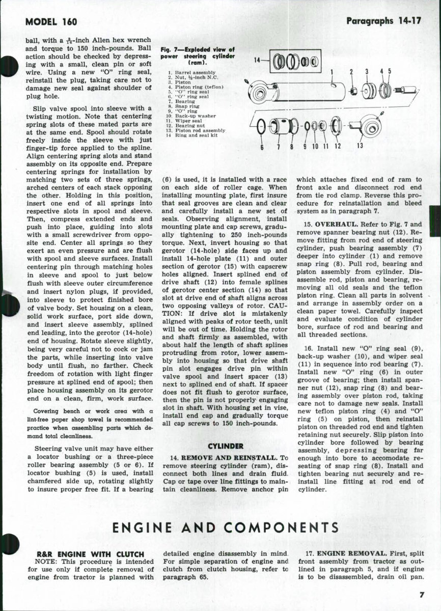
MODEL 160 Paragraphs 14-17 ball, with a ^^-inch Allen hex wrench and torque to 150 inch-pounds. Ball action should be checked by depress- ing with a small, clean pin or soft wire. Using a new **O" ring seal, reinstall the plug, taking care not to damage new seal against shoulder of plug hole. Slip valve spool into sleeve with a twisting motion. Note that centering spring slots of these mated parts are at the same end. Spool should rotate freely inside the sleeve with just finger-tip force applied to the spline. Align centering spring slots and stand assembly on its opposite end. Prepare centering springs for installation by matching two sets of three springs, arched centers of each stack opposing the other. Holding in this position, insert one end of all springs into respective slots in spool and sleeve. Then, compress extended ends and push into place, guiding into slots with a small screwdriver from oppo- site end. Center all springs so they exert an even pressure and are flush with spool and sleeve surfaces. Install centering pin through matching holes in sleeve and spool to just below flush with sleeve outer circumference and insert nylon plugs, if provided, into sleeve to protect finished bore of valve body. Set housing on a clean, solid work surface, port side down, and insert sleeve assembly, splined end leading, into the gerotor (14-hole) end of housing. Rotate sleeve slightly, being very careful not to cock or jam the parts, while inserting into valve body until flush, no farther. Check freedom of rotation with light finger pressure at splined end of spool; then place housing assembly on its gerotor end on a clean, firm, work surface. Covering bench or work area with a lint-free paper shop towel is recommended practice when assembling parts which de- mand total cleanliness. Steering valve unit may have either a locator bushing or a three-piece roller bearing assembly (5 or 6). If locator bushing (5) is used, install chamfered side up, rotating slightly to insure proper free fit. If a bearing Fig. 7—Exploded view of power steering eyiinder (ram). Barrel assembly Nut, 14-Inch N.C. Piston Piston ring (teflon) "O" ring seai "O" ring seal Bearing Snap ring **O" ring Baclc-up washer Wiper seal Bearing nut Piston rod assembly Ring and seal kit 6 7 (6) is used, it is installed with a race on each side of roller cage. When installing mounting plate, first insure that seal grooves are clean and clear and carefully install a new set of seals. Observing alignment, install mounting plate and cap screws, gradu- ally tightening to 250 inch-pounds torque. Next, invert housing so that gerotor (14-hole) side faces up and install 14-hole plate (11) and outer section of gerotor (15) with capscrew holes aligned. Insert splined end of drive shaft (12) into female splines of gerotor center section (14) so that slot at drive end of shaft aligns across two opposing valleys of rotor. CAU- TION: If drive slot is mistakenly aligned with peaks of rotor teeth, unit will be out of time. Holding the rotor and shaft firmly as assembled, with about half the length of shaft splines protruding from rotor, lower assem- bly into housing so that drive shaft pin slot engages drive pin within valve spool and insert spacer (13) next to splined end of shaft. If spacer does not fit flush to gerotor surface, then the pin is not properly engaging slot in shaft. With housing set in vise, install end cap and gradually torque all cap screws to 150 inch-pounds. CYLINDER 14. REMOVE AND REINSTALL. To remove steering cylinder (ram), dis- connect both lines and drain fluid. Cap or tape over line fittings to main- tain cleanliness. Remove anchor pin which attaches fixed end of ram to front axle and disconnect rod end from tie rod clamp. Reverse this pro- cedure for reinstallation and bleed system as in paragraph 7. 15. OVERHAUL. Refer to Fig. 7 and remove spanner bearing nut (12). Re- move fitting from rod end of steering cylinder, push bearing assembly (7) deeper into cylinder (1) and remove snap ring (8). Pull rod, bearing and piston assembly from cylinder. Dis- assemble rod, piston and bearing, re- moving all old seals and the teflon piston ring. Clean all parts in solvent and arrange in assembly order on a clean paper towel. Carefully inspect and evaluate condition of cylinder bore, surface of rod and bearing and all threaded sections. 16. Install new "O" ring seal (9), back-up washer (10), and wiper seal (11) in sequence into rod bearing (7). Install new "O" ring (6) in outer groove of bearing; then install span- ner nut (12), snap ring (8) and bear- ing assembly over piston rod, taking care not to damage new seals. Install new teflon piston ring (4) and "O" ring (5) on piston, then reinstall piston on threaded rod end and tighten retaining nut securely. Slip piston into cylinder bore followed by bearing assembly, depressing bearing far enough into bore to accomodate re- seating of snap ring (8). Install and tighten bearing nut securely and re- install line fitting at rod end of cylinder. ENGINE AND COMPONENTS R&R ENGINE WITH CLUTCH NOTE: This procedure is intended for use only if complete removal of engine from tractor is planned with detailed engine disassembly in mind For simple separation of engine and clutch from clutch housing, refer to paragraph 65. 17. ENGINE REMOVAL. First, split front assembly from tractor as out- lined in paragraph 5, and if engine is to be disassembled, drain oil pan.
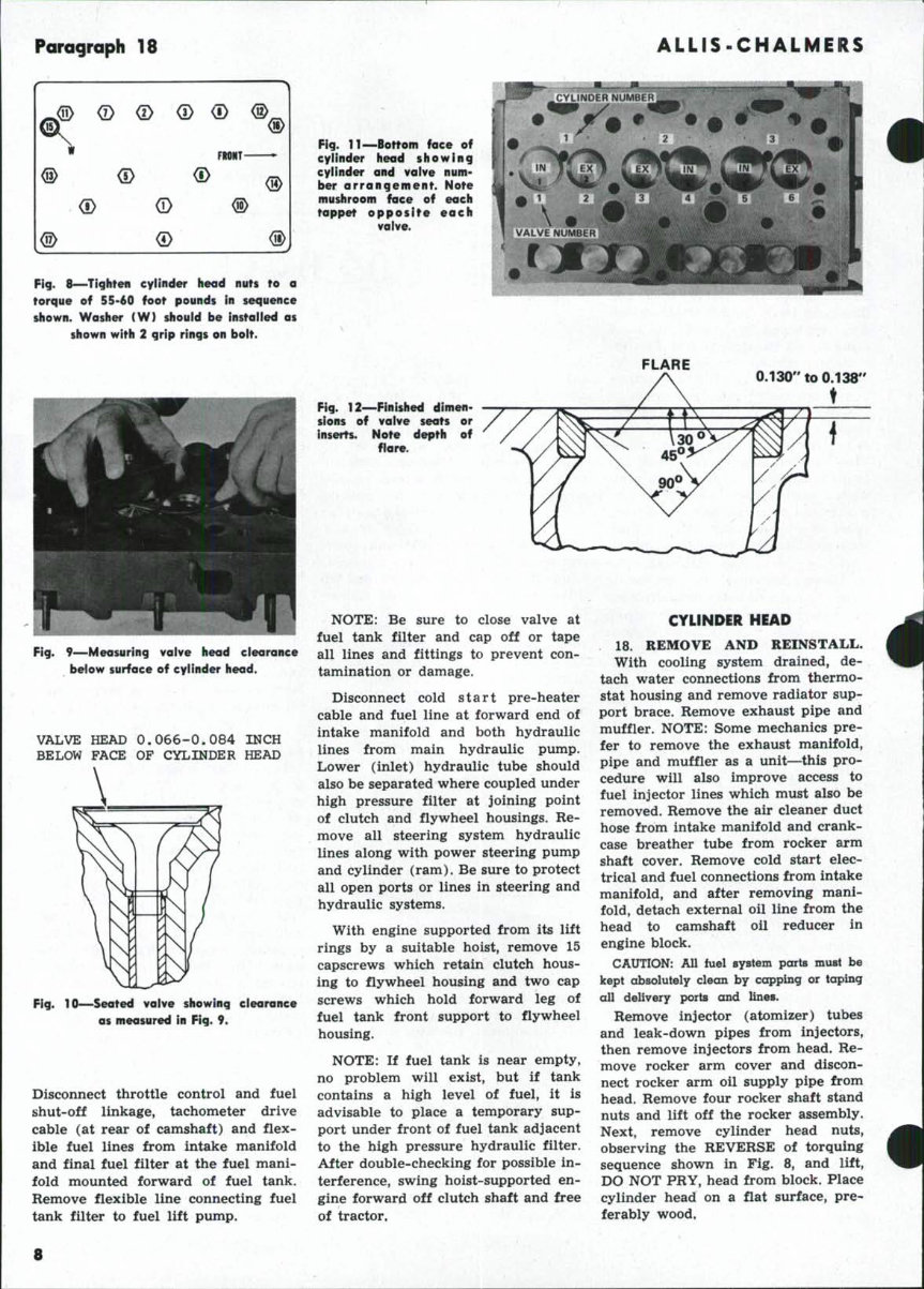
Paragraph 18 ALLIS-CHALMERS Fig. 8—Tighten cylinder head nuts to a torque of 5S-60 foot pounds in sequence shown. Washer (W) should be instaiied as shown with 2 grip rings on bolt. Fig. 9—Measuring valve head clearance below surface of cylinder head. VALVE HEAD 0.066-0.084 INCH BELOW FACE OF CYLINDER HEAD Fig. 10—Seated valve showing clearance as measured in Fig. 9. Disconnect throttle control and fuel shut-off linkage, tachometer drive cable (at rear of camshaft) and flex- ible fuel lines from intake manifold and final fuel filter at the fuel mani- fold mounted forward of fuel tank. Remove flexible line connecting fuel tank filter to fuel lift pump. Fig. 11—Bottom face of cylinder head showing cylinder and vaive num- ber arrangement. Note mushroom face of each tappet opposite each valve. 4 FLARE Fig. 12—Finished dimen- sions of vaive seats or inserts. Note depth of flare. 0.130" to 0.138" t NOTE: Be sure to close valve at fuel tank filter and cap off or tape all lines and fittings to prevent con- tamination or damage. Disconnect cold start pre-heater cable and fuel line at forward end of intake manifold and both hydraulic lines from main hydraulic pump. Lower (inlet) hydraulic tube should also be separated where coupled under high pressure filter at joining point of clutch and flywheel housings. Re- move all steering system hydraulic lines along with power steering pump and cylinder (ram). Be sure to protect all open ports or lines in steering and hydraulic systems. With engine supported from its lift rings by a suitable hoist, remove 15 capscrews which retain clutch hous- ing to flywheel housing and two cap screws which hold forward leg of fuel tank front support to flywheel housing. NOTE: If fuel tank is near empty, no problem will exist, but if tank contains a high level of fuel, it is advisable to place a temporary sup- port under front of fuel tank adjacent to the high pressure hydraulic filter. After double-checking for possible in- terference, swing hoist-supported en- gine forward off clutch shaft and free of tractor. CYLINDER HEAD 18. REMOVE AND REINSTALL. With cooling system drained, de- tach water connections from thermo- stat housing and remove radiator sup- port brace. Remove exhaust pipe and muffler. NOTE: Some mechanics pre- fer to remove the exhaust manifold, pipe and muffler as a unit—this pro- cedure will also improve access to fuel injector lines which must also be removed. Remove the air cleaner duct hose from intake manifold and crank- case breather tube from rocker arm shaft cover. Remove cold start elec- trical and fuel connections from intake manifold, and after removing mani- fold, detach external oil line from the head to camshaft oil reducer in engine block. CAUTION: All fuel system parts must be kept absolutely clean by capping or taping all delivery ports and lines. Remove injector (atomizer) tubes and leak-down pipes from injectors, then remove injectors from head. Re- move rocker arm cover and discon- nect rocker arm oil supply pipe from head. Remove four rocker shaft stand nuts and lift off the rocker assembly. Next, remove cylinder head nuts, observing the REVERSE of torquing sequence shown in Fig. 8, and lift, DO NOT PRY, head from block. Place cylinder head on a flat surface, pre* ferably wood. ^ • 8
MODEL 160 Paragraphs 19-20 TOP FACE OF CYLiNDER HEAD \ J I 0.584-0.594 INCH 20*^ CHAMFER Fig. 13 — New vaive guides should be pressed In to dimension shown. FROMT- Fig.. 15A—With number 1 cyiinder on com- pression strolce (see paragraph 20) ad- just valves 1, 2, 3 and 5 to 0.012 coid or 0.010 hot. Refer to Fig. 15B to continue adjustment. IISILET VALVE EXHAUST VALVE INLET A-1.874" to 1.875" B - 0.248" to 0.250" C - 0.040" to 0.050" (Radius) Fig. 14—Dimensions for machining counterbores for renewed vaive seats. Install new valve guide first to provide accurate center far machine cut- ter piiot. EXHAUST A-1.678" to 1.679" B-0.310" to 0.312" C - 0.015" (Maximum Radius) Before installing head, be sure that all block and head passages for cool- ant and oil are clean and clear and properly aligned with openings in new head gasket. Note position of FRONT and TOP marks on new gasket. Re- moval of surface defects by milling head is allowable up to 0.012, or until total thickness of head is reduced to 2.988 from original 3.0. If and when head is resurfaced, valve height must be measured as in paragraph 19, and by procedure shown in Fig. 9 & 10. Injector nozzle protrusion from under- surface of the head must never exceed 0.184. Do not shim under the injector to reduce this dimension. With all mating surfaces thoroughly clean, in- stall new treated head gasket dry and with two grip rings on stud bolt shown as No. 15 in Fig. 8, install cyl- inder head. Observing the sequence of Fig. 8, torque all cylinder head nuts to 55-60 foot-pounds. Be sure to install washer under No. 15, as shown. Install rocker shaft assembly, perform valve tappet adjustment as in para- graph 20. Complete the assembly, run engine until normal operating tem- perature is reached, then retorque head nuts and readjust tappet gap to specifications. VALVES AND SEATS 19. As manufactured, intake and exhaust valves are directly seated into cylinder head. All valve faces are production ground to 45® and seats are flared 30*, to the surface of cylinder heads, with preferred seat width of ^-inch. See Fig. 12. Loca- tions of valve heads and seats are numbered consecutively front to rear as shown in Fig. 11. Clearance of valve heads must be held within indi- cated tolerances, measured as shown in Fig. 9 & 10. When such clearance cannot be achieved, replacement seats are available for refitting heads as shown in Fig. 14. Note: To insure accuracy in machining counterbores for replacement valve seats, a new valve guide must be installed, observ- ing placement and dimensions shown in Fig. 13. Valves should be discarded if thickness of margin is less than N Fig. 15B—After adjusting vaives 1, 2. 3 and 5. (Fig. 15A) rotate engine ane revo- iution (360°) and adjust vaives 4 and 6. Tappet gap is 0.012 cold or 0.010 hot. . Specifications are as follows: Face Angle, In. & Ex 45® Stem Dia., In. & Ex *0.311-0.312 Valve Length, In. & Ex 4.5 Head Dia., In 1.532-1.536 Ex 1.313-1.317 Head Margin, Min ^-inch Guide I.D., In. & Ex. . .**0.3145-0.3155 Head Clearance, In. & Ex.. .0.066-0.084 Tappet Gap, In. & Ex. Hot 0.010 Cold 0.012 Discard if 0.310 or scored. **Discard if more than 0.3155. TAPPET GAP ADJUSTMENTS 20. A two-position procedure for adjusting valve lash (tappet clear- ance) is both practical and recom- mended. To make the adjustment, proceed as follows: Rotate engine (injectors removed) until key way in crankshaft pulley is at top and both valves of number one cylinder are fully closed—this is compression stroke. Refer to Fig. 15 A, and adjust tappets to 0.012 cold (0.010 hot) on valves numbered 1, 2, 3 and 5. Then, refer to Fig. 15B, rotate engine 360**, (one revolution) and set tappets 4 and 6. If head is re-torqued following this adjustment or if rocker shaft is
Paragraphs 21-24 ALLIS-CHALMERS removed, repeat the process with final setting at 0.010 for all valves when engine is at normal operating temperature. ROCKER ARMS AND SHAFT 21. After rocker shaft has been dis- assembled and thoroughly cleaned, with parts laid out in assembly sequence, it is advisable to check rocker arms (levers) for condition. Rocker arms should be a slip fit on the shaft and the bushing bore should not exceed 0.6257 or a measured fit to the shaft should not exceed 0.0034 clearance. Rockers are complete as- semblies and new bushings cannot be fitted. On reassembly, correct normal position of the slotted end of rocker arm shaft is shown in relation to a punched mark in front stand. See Fig. 16. This arrangement controls flow of oil to rocker arms. When need for increase or decrease of flow is confirmed, flow may be cut back by turning shaft slot to ver- tical« or increased by turning toward hori- lontal, which is the maximum flow rate position. VALVE GUIDES 22. Replacement cast iron valve guides are available pre-sized for press fit and do not require reaming. Inside diameter of guide is 0.3145- 0.3155 for both intake and exhaust with a stem to guide clearance of 0.0025-0.0045. If maximum figures are exceeded, renewal of guides is indi- cated. Consult Fig. 13, and press in new guides with 20"* chamfered end toward combustion chamber, observ- ing 0.584-0.594 clearance from top of new guide to top surface of cylinder head. While pressing, it is advisable to use a pilot drift 0.002 smaller than guide inside diameter. IMPORTANT: If guides only are renewed, be sure to reface valve seats lightly to insure proper concentric seal of valve faces to seats. VALVE SPRINGS 23. Springs are interchangeable be- tween intake and exhaust valves, and early models use two springs on each valve. See Fig. 17 for overall arrange- ment. The following table proposes specifications against which springs should be tested and compared. Before using spring tester, springs should be evaluated by inspection for discolor- ation, bent coils, ends out of square, or other apparent damage. Fig. 16 —View of front rocker arm stand showing correct position of shaft slot for normal oil flow control. 1-Punch mark on stand. 2-Correct (30° from verticai) position of siot. 4 Fig. 17—Intake and ex- haust valve assemblies for early models. Late mod- els do not have inner springs (4). 1. Kxliaust valve *J. Intake valve '{. Spring seats •1. Inner valve sprlngfl. early models 5. Outer valve springs 0 Upper spring caps 7. Retainers Spring Free Length, I^. & Ex. Outer lfl inches Inner* 1% inches Length, Valve Closed, In. & Ex. Outer 1^ inches Inner l^^ inches Pressure, Valve Closed, In. & Ex. . Outer 21-25 lbs. Inner 7-9 lbs. Length, Valve Open, In. & Ex. Outer 1^ inches Inner H inches Pressure, Valve Open, In. & Ex. Outer 48-52 lbs. Inner 21-25 lbs. *Inner spring discontinued in pro- duction following September 1970. There is no change in specifications for the single outer spring. VALVE TAPPETS 24. Valve tappets (cam followers) are a snug slip fit in bored hole.s in the cylinder head. Normal wear is negligible; however, if mushroom face, adjustment threads, tappet body or screw head have been damaged due to overheating, oil starvation or other abnormal condition, renew tappet. New tappets should fit with side clearance of 0.0008-0.0034 between tappet body and cylinder head bore. With cylinder head removed, tappets easily withdrawn when adjusting screw and locknut are removed. Be sure of observe location arrangement for convenience in reassembly. Tap- pets, like valves, must always be re- turned to same location from which removed. • 10
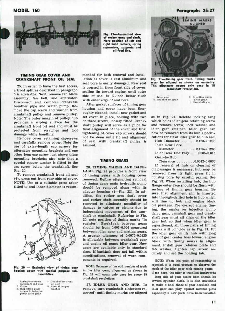
MODEL 160 Fig. 19—Assembled view of rocker arms and shaft. Note position of left and right hand rockers, spring separators, supports and oil feed line. TIMING GEAR COVER AND CRANKSHAFT FRONT OIL SEAL 25. In order to have the best access, a front split as described in paragraph 5 is advisable. Next, remove fan blade assembly, fan belt, and alternator. Disconnect and remove crankcase breather pipe and water pump. Re- move the cap screw and washer from crankshaft pulley and remove pulley. Note: The outer margin of pulley hub provides a wiping surface for the crankshaft front oil seal and must be protected from scratches and tool damage while handling. Remove cover retaining capscrews and carefully remove cover. Note the use of extra-length cap screws for alternator mounting brackets and one other long cap screw just above these mounting brackets; also note that a special copper washer is fitted to the cap screw below the crankshaft. See Fig. 20. To remove crankshaft front oil seal (4), press out from rear side of cover. NOTE: Use of a suitable press arbor fitted to seal inner diameter is recom- Fig. 20 — Exploded view of timing gear housing cover with special purpose sub- assemblies. 1. Spring—controls camshaft end play 2. Cover 3. Inspection plate— access to injection pump drive gear 4. Crankshaft front oil seal 5, Special copper washer mended for both removal and instal- lation as cover is cast aluminum and seal bore is easily damaged. New seal is pressed in from front side of cover, sealing lip toward engine, until outer side of seal is %-inch below flush with outer edge of seal bore. After gasket surfaces of timing gear housing and cover have been thor- oughly cleaned, install new gasket and set cover in place, holding with two or three screws, loosely fitted. Crank- shaft pulley will serve as a pilot for final alignment of the cover and final tightening of cover cap screws should not be done until fit and alignment of seal with crankshaft pulley is assured. TIMING GEARS 26. TIMING MARKS AND BACK- LASH. Fig. 21 provides a front view of timing gears with housing cover removed. Before attempting removal of timing gears main hydraulic pump should be removed along with its adapter housing (1—Fig. 22). In ad- dition, the rocker arm shaft cover and rocker shaft assembly should be removed to eliminate possibility of damage to valves or pistons due to independent movement of the cam- shaft or crankshaft. Referring to Fig. 20, note position of timing marks "in register". Backlash between gears should be from 0.003-0.006 measured between idler gear and mating gears. A greater tolerance of 0.0075-0.0125 is allowable between crankshaft gear and engine oil pump idler gear. New gears are available only in standard sizes. If backlash does not fall within specifications, renewal of worn com- ponents is required. NOTE: Because of the odd number oi teeth in the idler gear, alignment as shown in Fig. 21 will occur only once for every 18 crankshaft revolutions. 27. IDLER GEAR AND HUB. To remove, turn crankshaft (injectors re- moved) until timing marks are aligned Paragraphs 25-27 f I TIMING MARKS ALIGNED Fig. 21—Timing gear train. Timing marks must be aligned as shown on assembly. This alignment occurs only once in 18 crankshaft revolutions. 1. Idler gear ii. Crankshaft > .t. Injection pump drive gear t. Camshaft gear as in Fig. 21. Release locking tang which holds idler gear retaining screw and remove screw, lock washer and idler gear retainer. Idler gear can now be removed from its hub. Specifi- cations for fit of idler gear to hub are: Hub Diameter 2.123-2.1238 Idler Gear Bore Diameter 2.125-2.1266 Idler Gear End Play ... . 0.005-0,015 Gear-to-Hub Clearance 0.0012-0.0036 If renewal of hub or clearing of' oil passages is necessary, hub may be removed from its light press fit in housing bore by careful prying. See Fig. 23. When installing hub, the hub flange outer face should be flush with surface of timing gear housing. Be sure that alignment pin is inserted into through-drilled hole in hub which will line up hub and engine block oil passages. For correct engine tim- ing, the marks on injection pump drive gear, camshaft gear and crank- shaft gear must all align on the idler gear hub so that when idler gear is repositioned, all three pairs of timing marks will coincide as in Fig. 21. Fit the idler gear on its hub with long side of gear center boss toward engine block with timing marks in align- ment. Install gear retainer plate and tab washer, tighten cap screw se- curely and set the holding tab. NOTE: When ihis point o! reassembly is reached, it is good practice to observe the mesh of the idler gear with mating gears— if too deep, the idler is installed backwards —long side of gear center boss should be toward cylinder block. It is also advisable to make a final check of gear backlash and idler gear end play against retainer plate especially if new parts have been installed.
This comprehensive Allis Chalmers AC 160 Tractor Shop Service Repair Manual is an essential resource for maintaining and servicing your equipment. It contains detailed diagrams and manufacturer specifications, making it invaluable for professional mechanics and DIY enthusiasts alike.
The manual offers simple navigation with convenient chapter bookmarks and the ability to search by keyword. You can easily print the entire manual or specific sections relevant to your work.
INSTANT - NO WAITING
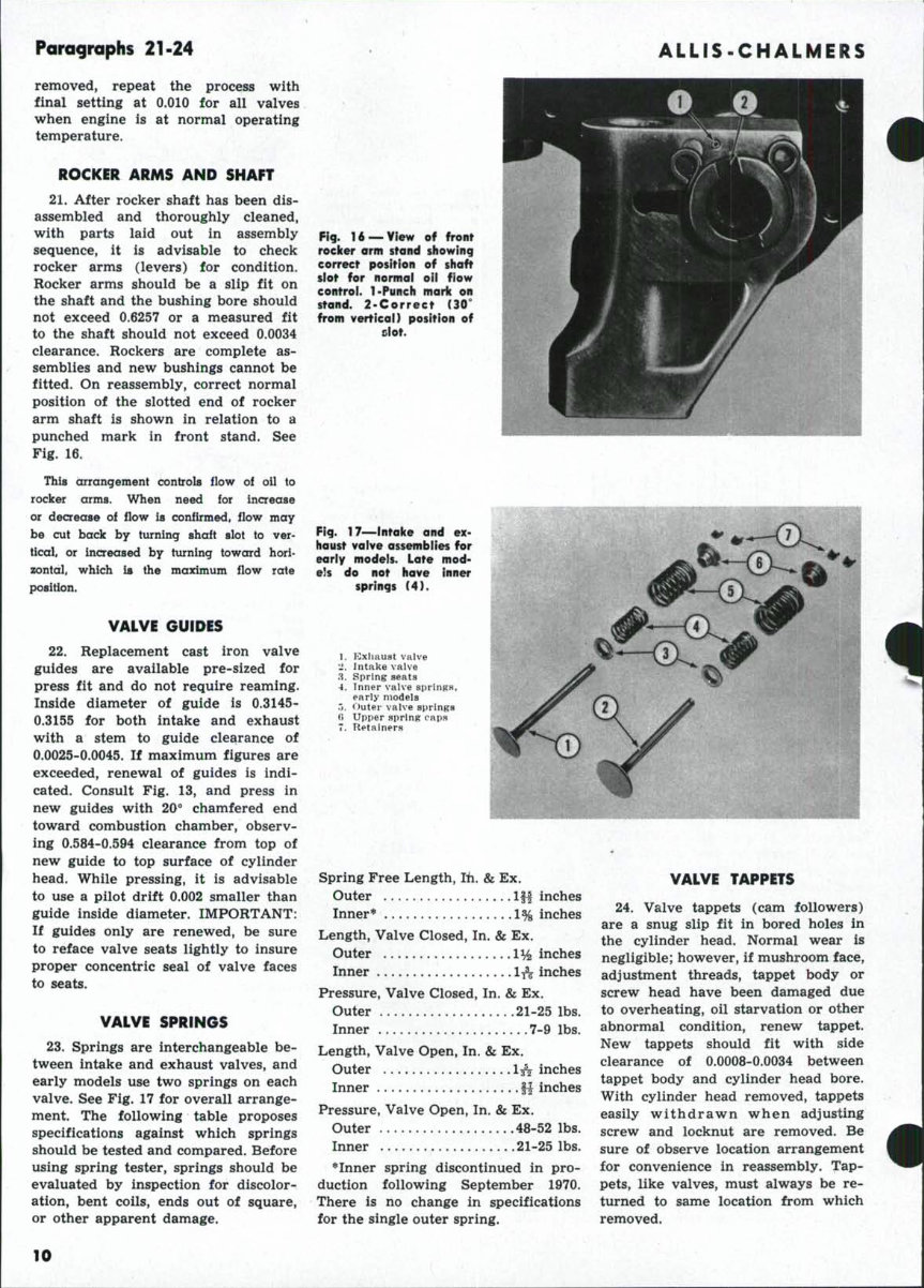
LANGUAGE: English
FORMAT: PDF
COMPATIBLE: Win/Mac
SEARCHABLE - BOOKMARKED - INDEXED
Each chapter is fully bookmarked for easy navigation, allowing quick access to the necessary service repair procedures. The manual includes detailed illustrations, exploded diagrams, drawings, and photos to guide you through the repair processes.
It is completely indexed, bookmarked, and searchable, covering essential sections such as brakes, clutch, cooling system, diesel fuel system, electrical system, engine components, hydraulic system, power take-off, steering system, transmission, and more. The inclusion of numerous pictures, diagrams, and illustrations makes it ideal for tune-ups, regular maintenance, or repairs.
Technical details and step-by-step instructions are provided, ensuring that all necessary information is readily available for your repair needs.
For immediate access to this manual, simply click the green & white "NOW" button at the top right-hand side of this page. If you require additional manuals, feel free to email us as we have a wide selection available.
Recently Viewed
5,521,897Happy Clients
2,594,462eManuals
1,120,453Trusted Sellers
15Years in Business
Price:
Actual Price:
Allis Chalmers 160 Tractor Shop Service Repair Manual - INSTANT