

Cameco CH2500 CHOPPER Combine Repair Manual 2001
What's Included?
Fast Download Speeds
Online & Offline Access
Access PDF Contents & Bookmarks
Full Search Facility
Print one or all pages of your manual

CH2500 CHOPPER COMBINE
2001 REPAIR MANUAL
Table of Contents
Introduction
Section 1Safety Recommendations
Section 0001General Specifications
Section 0002General Capacities
Section 0003Torque Specifications
Section 0004Fluid Recommendations
Section 0005General Information
Section 0006Service Points
Section 0100Hydrostatic Transmission
Section 0200Main Hydraulic System
Section 0300Steering System
Section 0600Operators Station
Section 1000Engine and Auxiliary System
Section 1200Final Drive
Section 1300Wheel and Track
Section 3100Topper System
Section 3200Crop Divider System
Section 3300Basecutter System
Section 3400Feed Roller System
Section 3500Chopper System
Section 3600Cleaning System
Section 3700Elevator System
INDEX

fi
CH2500 CHOPPER COMBINE
2001 REPAIR MANUAL
Section 1Safety Recommendations
Safety and You ................................................ 1-3
Operation Safety ............................................. 1-3
Service Safety ................................................. 1-4
Safety in Your Service Area ........................... 1-5
Safety when Cleaning or Storing .................. 1-6
Safety Nevers .................................................. 1-6
Recognize Safety Information ....................... 1-7
Understand Signal Words .............................. 1-7
Follow Safety Instructions ............................. 1-8
Protect Bystanders ......................................... 1-8
Use Handles and Steps .................................. 1-9
Prevent Machine Runaway ............................ 1-9
Avoid Exhaust Fumes .................................... 1-10
Keep Riders off Machine ................................ 1-10
Handle Fuel SafelyAvoid Fires ................... 1-11
Safely Service Accumulator .......................... 1-11
Safely Service Cooling System ..................... 1-12
Prepare For Emergencies .............................. 1-12
Wear Protective Clothing ............................... 1-13
Use Safety Lights and Devices ...................... 1-13
Use Cylinder Safety Stops ............................. 1-14
Practice Safe Maintenance ............................ 1-14
Avoid High Pressure Fluids ........................... 1-15
Use Caution on Hillsides ............................... 1-15
Stopping and Parking .................................... 1-16
Service Tires Safely ....................................... 1-17
Transport Combine Safely ............................. 1-17
Avoid Electrical Power Lines ......................... 1-18
Keep Hands Away From Knives .................... 1-18
Avoid Contact with Moving Parts .................. 1-19
Dispose of Waste Properly ............................. 1-19
Fire Prevention ............................................... 1-20
Safety Recommendations .............................. 1-21
Combine Safety .............................................. 1-21
Section 0001General Specifications
250 HP Specifications .................................... 0001-3
250 HP Description ......................................... 0001-4
250 HP Preliminary Service Intervals ............ 0001-4
250 HP Common Engine Wear Parts ............. 0001-4
270 HP Specifications .................................... 0001-5
270 HP Description ......................................... 0001-6
270 HP Preliminary Service Intervals ............ 0001-6
270 HP Common Engine Wear Parts ............. 0001-6
325 HP Specifications .................................... 0001-7
325 HP Description ......................................... 0001-8
325 HP Preliminary Service Intervals ............ 0001-8
325 HP Common Engine Wear Parts ............. 0001-8
Specifications ................................................. 0001-9
Description ..................................................... 0001-10
Preliminary Service Intervals ........................ 0001-10
Common Engine Wear Parts ......................... 0001-10
Standard Efficiency Hydraulic ....................... 0001-11
TransmissionTrack ..................................... 0001-11
Varitorq TransmissionWheel ...................... 0001-11
Oil Cooler Fan Motor ..................................... 0001-11
Steering CircuitWheel ................................ 0001-11
Cylinder Control Circuit ................................. 0001-11
TopperWhole Top ........................................ 0001-12
TopperShredder .......................................... 0001-12
TopperCollectors ........................................ 0001-12
Basecutter226.8 L/Min (250 HP, 60 GPM) ... 0001-12
Basecutter302.4 L/Min (80 GPM) ................ 0001-12
Crop Dividers ................................................. 0001-12
Power Feed RollerLow Basecutter ............. 0001-13
Power Feed RollerHigh Basecutter ............ 0001-13
Chopper Drums .............................................. 0001-13
Chopper Drums250 HP, 60 GPM ................. 0001-13
Feed Roller Oil Division ................................ 0001-13
Front Feed Roller Set ..................................... 0001-14
Feed RollerA1, A2, B1, and BL (Buttlifter) .. 0001-14
Rear Feed Roller Set ...................................... 0001-14
Feed RollerB2 ............................................. 0001-14
Feed RollerA3, A4, A5, B3, B4, and B5 ....... 0001-14
Fixed Primary Extractor ................................. 0001-14
Variable Primary Extractor ............................ 0001-14
Secondary Extractor ...................................... 0001-15
Elevator .......................................................... 0001-15
Elevator Functions ......................................... 0001-15
Secondary Extractor ...................................... 0001-15
Section 0002General Capacities
Combine Capacities ....................................... 0002-3
Tire Inflation Pressure ................................... 0002-3
Section 0003TorqueSpecifications
Suggested Torque Values For Grades ........... 0003-3
Conversion Factors ........................................ 0003-4
Section 0004Fluid Specifications
Caterpillar Engine Coolant Requirements .... 0004-3
Caterpillar Antifreeze ..................................... 0004-3
Engine Coolant Requirements ...................... 0004-3
John Deere Coolant ...................................... 0004-3
John Deere Cool-Gard ................................... 0004-3
Caterpillar Water ............................................. 0004-3
Caterpillar Conditioners ................................ 0004-3
John Deere Antifreeze/Summer Coolant ....... 0004-3

ii
TABLE OF CONTENTS
John Deere Engine Coolant Requirements .. 0004-4
Hydraulic Fluid (World) .................................. 0004-5
Hydraulic Fluid (Australia) ............................. 0004-5
Diesel Fuel ...................................................... 0004-5
Engine Oil (Caterpillar) .................................. 0004-5
Engine Break-in Oil (John Deere) .................. 0004-5
Diesel Engine Oil ........................................... 0004-6
Gear Oil .......................................................... 0004-6
Gear OilFinal Drive ..................................... 0004-6
Grease ............................................................. 0004-6
Section 0005Service Points
Straight O-Ring Boss Fittings ....................... 0005-3
Angled O-Ring Boss Fittings ......................... 0005-3
37 Flare Cone Fittings .................................. 0005-3
Hex Flats Recommended Rotation ................ 0005-4
Four Bolt Flange Fittings ............................... 0005-4
Flange Metric Bolt Torque Chart .................... 0005-5
Flange SAE Bolt Torque Chart ....................... 0005-5
Conversions .................................................... 0005-6
Weight Measure .............................................. 0005-6
Length Measure .............................................. 0005-6
Metric (SI) Measurements ............................ 0005-6
Metric to English ............................................ 0005-6
English to Metric ............................................ 0005-6
Multiplication Factors .................................... 0005-7
Temperature Conversion Chart ...................... 0005-7
Conversion Formulas ..................................... 0005-7
Recommended Supplies ............................... 0005-8
Hydraulic Gauge Kit ....................................... 0005-10
Specialty Tools and Part Numbers ................ 0005-11
Section 0006Service Points
Combine Component Locations ................... 0006-3
Combine Service Point Locations ................. 0006-4
Combine Grease Point Locations ................. 0006-5
Grease Point Locations .................................. 0006-6
Section 0100Hydrostatic Transmission
Hydrostatic Pump .......................................... 0161-3
Manual and Electrical Displacement Control 0161-4
Suggested Tools And Supplies ..................... 0161-4
General Repair Instructions ........................... 0161-4
Displacement Control Replacement .............. 0161-4
Orifice Check Valve Replacement .................. 0161-5
Charge Pressure Relief Valve Replacement .. 0161-5
Shaft Seal Replacement ................................. 0161-6
Multifunction Valve Cartridge ........................ 0161-6
Charge Pump Disassembly ........................... 0161-6
Charge Pump Reassembly ............................ 0161-7
Variable Displacement Motor (Wheel) ........... 0167-1
Shaft Seal Disassembly ................................. 0167-2
Inspect ............................................................ 0167-2
Assembly ........................................................ 0167-2
About Servicing The Motor ............................ 0167-3
Cartridge Disassembly ................................... 0167-4
Housing Disassembly .................................... 0167-5
Shaft Assembly .............................................. 0167-6
Piston Ring ..................................................... 0167-7
Bearing Plate, Valve Segment, and Cylinder . 0167-8
4-Way Valve and Feedback Springs ............... 0167-9
Housing Assembly ......................................... 0167-10
Housing Assembly ......................................... 0167-11
Fixed Displacement Motor (Track) ................. 0167-12
Cartridge Assembly ....................................... 0167-13
Piston Rings ................................................... 0167-14
Cylinder Block Assembly .............................. 0167-15
End Cap to Main Housing Assembly ............ 0167-17
Track Fixed Displacement Motor
Disassembly .............................................. 0167-18
Variable Displacement Motor ........................ 0167-19
Cleanliness ..................................................... 0167-20
Disassembly ................................................... 0167-20
Assembly ........................................................ 0167-22
Section 0200Main Hydraulic System
Multiple Gear Pump ....................................... 0261-5
World Multiple Gear Pump ............................ 0261-6
World Multiple Gear Pump (Piggyback) ........ 0261-7
Multiple Gear Pump Repair ........................... 0261-8
Suggested Tools ............................................. 0261-8
Repair Precautions ......................................... 0261-8
Bushing Removal Tool ................................... 0261-8
Seal Removal Tool ......................................... 0261-8
Bushing Installation Tool ............................... 0261-8
Special Steel Sleeve ...................................... 0261-8
Seal Installation Tool ..................................... 0261-9
Disassembly ................................................... 0261-9
Clean and Inspect .......................................... 0261-9
Assembly ........................................................ 0261-10
Start Up Procedure ......................................... 0261-11
Recommended Test Procedure ...................... 0261-11
Triple Vane Pump ........................................... 0261-13
General Repair ............................................... 0261-14
Pump Disassembly ........................................ 0261-14
Cartridge Kit Disassembly ............................. 0261-14
Clean and Inspect .......................................... 0261-15
Before Assembly ............................................ 0261-15
Cartridge Kit Assembly .................................. 0261-15
Pump Assembly ............................................. 0261-16
Pump Not Delivering Fluid ............................ 0261-17
Insufficient Pressure Built-Up ....................... 0261-17
Pump Making Noise ....................................... 0261-17
Five Bank Directional Valve ........................... 0262-1
Suggested Tools ............................................. 0262-2
External Relief Settings ................................. 0262-2
Overhaul ......................................................... 0262-2
Valve Bank Disassembly ................................ 0262-2
Spool Disassembly ........................................ 0262-3

iii
TABLE OF CONTENTS
Cleaning, Inspection, And Repair .................. 0262-4
Assembly ........................................................ 0262-4
Spool AssemblySpring Centered .............. 0262-4
Valve Section Assembly ................................ 0262-5
Valve Bank Assembly ..................................... 0262-5
Section Disassembly ..................................... 0262-5
Preparation of Parts ....................................... 0262-6
Section Assembly .......................................... 0262-6
Relief Valve ..................................................... 0270-1
Troubleshooting ............................................. 0270-2
Erratic Pressure ............................................. 0270-2
Low or No Pressure ....................................... 0270-2
Plug Vent Connection .................................... 0270-2
Excessive Noise or Chatter ............................ 0270-2
Repair ............................................................. 0270-2
Necessary Tools ............................................. 0270-2
Removal .......................................................... 0270-2
Disassembly ................................................... 0270-2
Clean And Inspect .......................................... 0270-3
Assembly ........................................................ 0270-3
Troubleshooting ............................................. 0270-5
Erratic Pressure ............................................. 0270-5
Low or No Pressure ....................................... 0270-5
Plug Vent Connection .................................... 0270-5
Excessive Noise or Chatter ............................ 0270-5
Repair ............................................................. 0270-5
Necessary Tools ............................................. 0270-5
Removal .......................................................... 0270-5
Section 0300Steering System
Priority Valve .................................................. 0362-3
Main Spool Repair ......................................... 0362-4
Relief Valve Adjustment ................................. 0362-4
Relief Valve Repair ......................................... 0362-4
Priority Valve .................................................. 0362-5
Main Spool Repair ......................................... 0362-6
Relief Valve Adjustment ................................. 0362-6
Relief Valve Repair ......................................... 0362-6
Steering Valve ................................................. 0362-7
Suggested Tools ............................................. 0362-8
Disassembly ................................................... 0362-8
Clean and Inspect .......................................... 0362-9
Reassembly .................................................... 0362-10
Troubleshooting ............................................. 0362-13
Steering Cylinder ........................................... 0362-15
Tools and Supplies ........................................ 0362-16
Disassembly ................................................... 0362-16
Clean and Inspect .......................................... 0362-16
Assembly ........................................................ 0362-17
Steering Linkage ............................................ 0362-18
Steering Bellcrank .......................................... 0362-19
Disassembly ................................................... 0362-19
Clean and Inspect .......................................... 0362-19
Assembly ........................................................ 0362-19
Toe-in Adjustment .......................................... 0362-19
Section 0600Operators Station
Window Replacement .................................... 0611-3
Operators Station .......................................... 0611-4
Cab Glass Replacement ................................. 0611-4
Front Glass Removal ..................................... 0611-4
Front Glass Installation ................................. 0611-4
Flat Glass Removal ........................................ 0611-5
Flat Glass Installation .................................... 0611-5
Upper Rh Glass Removal ............................... 0611-5
Upper Rh Glass Installation ........................... 0611-5
Section 1000Engne & Auxiliary System
Pump Drive ..................................................... 1070-3
Pump Drive Removal ..................................... 1070-4
Disassembly ................................................... 1070-4
Clean and Inspect .......................................... 1070-5
Assembly ........................................................ 1070-5
Section 1200Final Drive
Final Drive ...................................................... 1200-3
Suggested Tools ............................................. 1200-4
Disassembly ................................................... 1200-4
Install Spindle Nut ......................................... 1200-5
Assembly ........................................................ 1200-5
Start-Up After Repair ...................................... 1200-6
Maintenance ................................................... 1200-7
Oil Change IntervalGear Drive ................... 1200-7
Section 1300Wheel and Track
Right Side View .............................................. 1300-5
Track Assembly .............................................. 1300-5
Track Alignment ............................................. 1300-6
Roller Lubrication .......................................... 1300-6
Idler Lubrication ............................................. 1300-7
Track Shoe Tightening ................................... 1300-7
Track Shoe Inspection Torque ....................... 1300-7
Sprocket Tightening ....................................... 1300-7
Rear Axle Maintenance .................................. 1300-7
Track Adjustment ........................................... 1300-8
Front Idlers ..................................................... 1300-9
Lubrication ..................................................... 1300-9
Identifying Master Link For Chain Removal . 1300-10
Recoil Spring Repair ...................................... 1300-10
Recoil Spring Adjustment ............................. 1300-10
Specifications ................................................. 1300-10
Link Rail Wear ................................................ 1300-11
Link Rail Measurement .................................. 1300-11
Rebuildability ................................................. 1300-11
Link Percentage Worn Chart .......................... 1300-11
Sealed Track Bushings & Pins ...................... 1300-12
Bushing and Pin Wear ................................... 1300-12
Wear Measurement ......................................... 1300-12
Wear LimitsService and Destruction ......... 1300-12
Track Bushing Allowable Wear Chart ............ 1300-12

iv
TABLE OF CONTENTS
Internal Pitch Wear ......................................... 1300-13
Measurement Technique ................................ 1300-13
Detrimental Effects of Excessive Pitch ......... 1300-13
Allowable Wear ............................................... 1300-13
Internal Pitch Percentage Worn Chart ........... 1300-13
Track Rollers .................................................. 1300-14
Track Roller Lubrication ................................ 1300-14
Seal Assembly ............................................... 1300-14
Specifications ................................................. 1300-14
Carrier Roller .................................................. 1300-15
Carrier Roller Lubrication .............................. 1300-15
Carrier Roller Assembly ................................ 1300-15
Specifications ................................................. 1300-15
Sprocket Wear Patterns .................................. 1300-16
Sprocket Replacement ................................... 1300-16
Tip Gouged ..................................................... 1300-16
Rolling Undercarriage .................................... 1300-17
Roller Wear Diagnosis ................................... 1300-17
How To Measure Roller Wear ......................... 1300-17
Specifications ................................................. 1300-17
Carrier Roller Percentage Worn ..................... 1300-17
Track Roller Percentage Worn ....................... 1300-18
Rolling Undercarriage .................................... 1300-18
Flange To Boss Measurement ....................... 1300-18
Idler Tread Wear Measurement ...................... 1300-18
Swapping Idlers ............................................. 1300-18
Check Idler Flange Wear ................................ 1300-19
Flange Top Wear ............................................. 1300-19
Flange Side Wear ........................................... 1300-19
Idlers Percentage Worn Chart ........................ 1300-19
Track Shoe Problems ..................................... 1300-20
Grouser Wear Measurement .......................... 1300-20
Wear LimitsService and Destruction ......... 1300-20
Grouser Wear .................................................. 1300-20
Plate Wear and Leading/Trailing Edge Wear . 1300-21
Bolt Hole Wallowing Out ................................ 1300-21
Self-Locking Track Nut ................................... 1300-21
Sprocket Chain Roller Alignment ................. 1300-22
Wheel Assembly ............................................. 1300-23
Remove And Replace Front Wheel Bearings 1300-24
Suggested Tools ............................................. 1300-24
Remove Rear Wheel Assembly ...................... 1300-24
To Remove And Mount Tire ........................... 1300-24
Install Wheel Assembly .................................. 1300-25
Tire Pressure Specifications ......................... 1300-25
Section 3100Topper System
Collector, Crop Divider, Feed Roller, .............
and Elevator Motor ................................... 3100-3
Suggested Tools ............................................. 3100-4
Collector Motor .............................................. 3100-4
Disassembly ................................................... 3100-4
Clean and Inspect .......................................... 3100-5
Assembly ........................................................ 3100-5
Topper ............................................................. 3151-1
Topper Repair ................................................. 3151-2
Collector Drum and Motor Removal ............. 3151-2
Topper Assembly Removal ............................ 3151-2
Clean and Inspect .......................................... 3151-2
Drum and Topper Assembly .......................... 3151-2
Shredder Topper ............................................. 3151-3
Topper Repair ................................................. 3151-4
Collector Drum and Motor Removal ............. 3151-4
Topper Assembly Removal ............................ 3151-4
Clean and Inspect .......................................... 3151-4
Drum and Topper Assembly .......................... 3151-4
Scroll Cylinder ............................................... 3165-1
Suggested Tools ............................................. 3165-2
Disassembly ................................................... 3165-2
Clean And Inspect .......................................... 3165-2
Assembly ........................................................ 3165-3
Gear Motor ...................................................... 3167-1
Gear Motor Repair .......................................... 3167-2
Suggested Tools ............................................. 3167-2
Repair Precautions ......................................... 3167-2
Bushing Removal Tool ................................... 3167-2
Seal Removal Tool ......................................... 3167-2
Bushing Installation Tool ............................... 3167-2
Disassembly ................................................... 3167-3
Clean And Inspect .......................................... 3167-3
Assembly ........................................................ 3167-4
Start Up Procedure ......................................... 3167-5
Recommended Test Procedure ...................... 3167-5
Section 3200Crop Divider System
Crop Divider ................................................... 3251-3
Crop Divider Removal .................................... 3251-4
Disassembly ................................................... 3251-4
Clean and Inspect .......................................... 3251-4
Assembly ........................................................ 3251-4
Crop Divider Shoe Assembly ........................ 3251-4
Crop Divider Shoe Removal .......................... 3251-4
Twin Crop Divider .......................................... 3251-5
Twin Crop Divider Removal ........................... 3251-6
Clean and Inspect .......................................... 3251-6
Assembly ........................................................ 3251-6
Section 3300Basecutter System
Basecutter ....................................................... 3351-5
Basecutter Gearbox ........................................ 3351-6
Gearbox Removal ........................................... 3351-7
Gearbox Installation ....................................... 3351-7
Gearbox Disassembly .................................... 3351-7
Leg Shaft Removal ......................................... 3351-8
Pinion Gear Removal ..................................... 3351-8
Clean and Inspect .......................................... 3351-8
Before Assembly ............................................ 3351-9
Gearbox Assembly ......................................... 3351-10
Pinion Installation .......................................... 3351-10
Bearing Installation ........................................ 3351-10

v
TABLE OF CONTENTS
Leg Shaft Preassembly .................................. 3351-11
Assembly and Timing .................................... 3351-11
Timing Procedure (New Parts) ...................... 3351-12
Low Drive Basecutter Gearbox ...................... 3351-13
Basecutter Gearbox ........................................ 3351-14
Removal .......................................................... 3351-14
Disassembly ................................................... 3351-14
Clean and Inspect .......................................... 3351-14
Assembly ........................................................ 3351-15
Set Preload ..................................................... 3351-15
Adjust Clutch Overload Protection ............... 3351-16
Setting Procedure .......................................... 3351-16
Inspection ....................................................... 3351-16
Accumulator ................................................... 3360-1
Maintenance ................................................... 3360-2
Pre-Charge Checking Procedure ................... 3360-2
Removal .......................................................... 3360-2
Disassembly ................................................... 3360-2
Clean and Inspect .......................................... 3360-2
Assembly ........................................................ 3360-3
Directional Valve ............................................. 3362-1
Work Section .................................................. 3362-2
Introduction .................................................... 3362-3
Removal .......................................................... 3362-3
Disassembly ................................................... 3362-3
Spool Section Disassembly .......................... 3362-3
Clean and Inspect .......................................... 3362-3
Assembly ........................................................ 3362-4
Main Relief Valve ............................................ 3362-4
Work Port Relief Valve .................................... 3362-5
Basecutter Lift Cylinder (Wheel) .................... 3365-1
Disassembly ................................................... 3365-2
Clean and Inspect .......................................... 3365-2
Reassembly .................................................... 3365-3
Basecutter Lift Cylinder (Track) ..................... 3365-5
Suggested Tools ............................................. 3365-6
Disassembly ................................................... 3365-6
Clean and Inspect .......................................... 3365-6
Reassembly .................................................... 3365-7
Section 3400Feed Roller System
Power Finned Roller ...................................... 3451-3
Removal .......................................................... 3451-4
Disassembly ................................................... 3451-4
Clean And Inspect .......................................... 3451-4
Assembly ........................................................ 3451-4
Buttlifter Roller (BL) ....................................... 3451-5
Repair ............................................................. 3451-6
Clean and Inspect .......................................... 3451-6
Assembly ........................................................ 3451-6
Bottom Feed Roller (B1) ................................ 3451-7
Repair ............................................................. 3451-8
Clean and Inspect .......................................... 3451-8
Assembly ........................................................ 3451-8
Bottom Feed Roller (B2) & (B5) ...................... 3451-9
Repair ............................................................. 3451-10
Clean and Inspect .......................................... 3451-10
Assembly ........................................................ 3451-10
Bottom Feed Roller (B3) & (B4) .................... 3451-11
Repair ............................................................. 3451-12
Clean and Inspect .......................................... 3451-12
Assembly ........................................................ 3451-12
Feed Roller (A1) .............................................. 3451-13
Repair ............................................................. 3451-14
Clean and Inspect .......................................... 3451-14
Assembly ........................................................ 3451-14
Top Floating Feed Roller (A2, A3, A4, & A5) .. 3451-15
Repair ............................................................. 3451-16
Clean and Inspect .......................................... 3451-16
Assembly ........................................................ 3451-16
Section 3500Chopper System
Chopper Gearbox ........................................... 3551-3
Remove ........................................................... 3551-4
Clean and Inspect .......................................... 3551-4
Chopper Box PreAssembly ........................... 3551-4
Chopper Hub .................................................. 3551-6
Chopper Hubs Pre Assembly and Installed .. 3551-7
Chopper Drums .............................................. 3551-8
Chopper Drum Assembly .............................. 3551-9
Timing Gear Assembly and Adjustment ....... 3551-10
Differential Chopper Timing Gear ................. 3551-11
Slip Clutch ...................................................... 3551-12
Disassembly ................................................... 3551-13
Assembly (Flywheel & Slip Clutch) ............... 3551-13
Field Setting of Slip Clutch ........................... 3551-14
Clean and Close Box ...................................... 3551-14
Assembly Chopper Motors ............................ 3551-14
Assembly Chopper Deflector Shields ........... 3551-14
Install and Adjust Sill Plate ........................... 3551-14
Chopper SystemSix Blade ......................... 3551-15
Billet LengthSix Blade ................................ 3551-15
Chopper SystemFour Blade ....................... 3551-15
Billet LengthFour Blade ............................. 3551-15
Chopper SystemEight Blade ...................... 3551-15
Chopper Blades .............................................. 3551-16
Slip Clutch Adjustment .................................. 3551-16
Chopper Gearbox Lubrication ....................... 3551-16
Gearbox Oil Capacities .................................. 3551-16
Six Blade ........................................................ 3551-16
Four Blade ...................................................... 3551-16
Chopper System ............................................. 3551-17
Chopper System Operation ........................... 3551-17
Adjusting Chopper Blade Timing-Pinch ....... 3551-17
Chopper System ............................................. 3551-18
Differential Chopper Timing .......................... 3551-18
Chopper Motor12 Inch ................................ 3551-19
Suggested Tools ............................................. 3551-20
Disassembly ................................................... 3551-20
Clean and Inspect .......................................... 3551-21

vi
TABLE OF CONTENTS
Assembly ........................................................ 3551-21
Chopper Motor15 Inch ................................ 3551-24
Suggested Tools ............................................. 3551-25
Disassembly ................................................... 3551-26
Reassembly .................................................... 3551-29
Section 3600Cleaning System
Hydraulic Primary Extractor .......................... 3651-3
Primary Extractor Tachometer ....................... 3651-4
Elevator Boom ............................................... 3651-5
Fan Assy ......................................................... 3651-6
Installing The Hub To Motor Shaft ................. 3651-7
Installing Fan Blades, Doubler Plates, ..........
and Backing Plate ..................................... 3651-7
Safety Start Up ............................................... 3651-8
Fan Mounting-Primary Extractor ................... 3651-9
Disassembly ................................................... 3651-10
Preassembly Fan Hub and Blades ................ 3651-10
Preassembly Primary Extractor ....................
Direct Drive Motor ..................................... 3651-10
Install Primary Extractor Direct Drive Motor .
Into Primary Extractor Hood .................... 3651-10
Install Fan Hub Assembly .............................. 3651-11
Sill Roller Assembly ...................................... 3651-12
Disassembly ................................................... 3651-13
Assembly ........................................................ 3651-13
Variable Primary Extractor Pump ................. 3661-1
Manual Displacement Control ....................... 3661-2
Suggested Tools ............................................. 3661-2
Multi-Function Valve Adjustment .................. 3661-2
Stroke Limiter Adjustment ........................... 3661-3
Charge Relief Adjustment .............................. 3661-3
Minor Repair ................................................... 3661-3
General Repair ............................................... 3661-3
Manual Displacement Control Replacement . 3661-3
Orifice Check Valve Replacement .................. 3661-4
Charge Pressure Relief Valve Replacement .. 3661-4
Shaft Seal Replacement ................................. 3661-5
Multi-Function Valve Cartridge ......................
Replacement (2 per pump) ....................... 3661-5
Charge Pump Disassembly ........................... 3661-5
Reassembly .................................................... 3661-6
Wiper Motor .................................................... 3667-1
Suggested Tools ............................................. 3667-2
Disassembly ................................................... 3667-2
Clean and Inspect .......................................... 3667-3
Assembly ........................................................ 3667-3
Primary Extractor Motor ................................ 3667-5
Tools Required ............................................... 3667-6
Disassembly Shaft Seal ................................. 3667-7
Disassembly End Cover with Integral Shuttle
and Low Pressure Relief Valve ................. 3667-8
Disassembly of End Cover ............................ 3667-9
Disassembly of Rotating Group .................... 3667-9
Reassembly .................................................... 3667-12
Reassembly of Shaft Seal .............................. 3667-15
Reassembly of End Cover ............................. 3667-16
Shaft Bearing Cone Driver (End Cover end) . 3667-17
Low Clearance Bearing Puller ....................... 3667-19
Section 3700Elevator System
Standard Capacity Elevator System .............. 3740-3
Elevator Group ............................................... 3740-4
Chain Adjustment .......................................... 3740-4
Changing Chain and Sprockets .................... 3740-4
Headshaft Repair ............................................ 3740-5
Disassembly ................................................... 3740-5
Assembly ........................................................ 3740-5
Chain Removal On Repair ............................. 3740-6
High Capacity Elevator System ..................... 3740-7
High Capacity Elevator Drive ......................... 3740-8
Manual Chain Adjustment For .......................
High Capacity Elevators ........................... 3740-9
High Capacity Elevator .................................. 3740-10
Grease Cylinder Elevator Chain Adjustment 3740-10
Elevator Swing Table ..................................... 3743-1
Description ..................................................... 3743-2
Removal .......................................................... 3743-2
Clean and Inspect .......................................... 3743-2
Assembly ........................................................ 3743-2
Elevator Swing Table ..................................... 3743-3
Description ..................................................... 3743-4
Removal .......................................................... 3743-4
Clean and Inspect .......................................... 3743-4
Assembly ........................................................ 3743-4
Elevator Swing Cylinder ................................ 3765-1
Disassembly ................................................... 3765-2
Clean and Inspect .......................................... 3765-2
Guide Rod Seal Installation ........................... 3765-2
Piston Seal Installation .................................. 3765-2
Cylinder Assembly ......................................... 3765-3
Elevator Lift Cylinder ..................................... 3765-4
Disassembly ................................................... 3765-5
Clean and Inspect .......................................... 3765-5
Piston Seal Installation .................................. 3765-6
Cylinder Assembly ......................................... 3765-6

CAMECO INDUSTRIES, INC.
INTRODUCTION
Read this manual carefully to learn how to correctly operate and service your harvester. Failure
to do so could result in personal injury or equipment damage.
This manual should be considered a permanent part of your machine and should remain with the
harvester.
Measurements in this manual are given in both customary US units and metric equivalents. Use
only specified replacement parts and fasteners. Inch and metric fasteners require a specific inch or
metric wrench or socket.
Right-hand and left-hand sides are determined by facing in the direction of forward travel.
All information, illustrations, specifications, and recommendations in this manual are based on
the latest information available at the time of publication. CAMECO reserves the right to make changes
at any time without notice or obligation.
Write the product serial number in a secure place away from the harvester. An appropriate place
would be in the parts manual since it is recommended to have your serial number available when ordering
parts. This number will also aid in tracing the harvester in the event that it is stolen.
Carefully read all safety messages in this manual and on your harvester. Precautionary statements
like CAUTION and IMPORTANT are followed by specific instructions for personal and machine safety.
Please take time to read them.
CH2500 Chopper Harvester
CAMECO INDUSTRIES, INC.
INTRODUCING THE HARVESTER
CAMECO INDUSTRIES, INC.
INTRODUCING THE HARVESTER
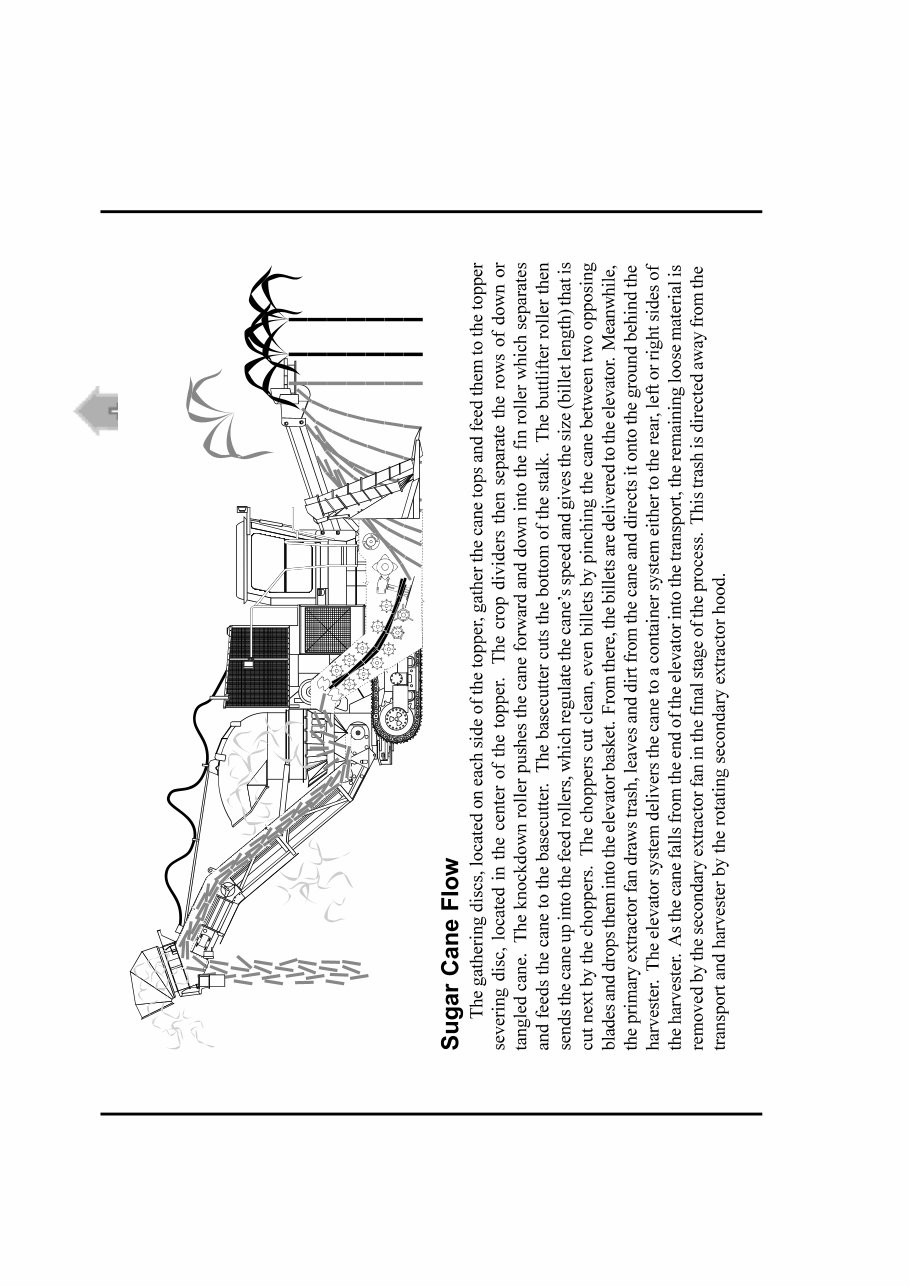
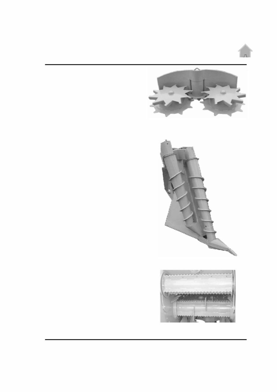
Topper
Severs the top leaves from the cane.
Crop Divider
Separates rows of down or tangled cane. It uses
dual croplift scrolls that turn in a screwing motion to pick-
up the down cane and separates it from the next row.
Power Knockdown Roller
Pushes cane into optimal position for feeding. Also
helps in feeding heavily lodged cane into the throat and to
prevent the cane from getting hung-up on the front of the
harvester.
You're Reading a Preview
What's Included?
Fast Download Speeds
Online & Offline Access
Access PDF Contents & Bookmarks
Full Search Facility
Print one or all pages of your manual
$52.99
Viewed 86 Times Today


Secure transaction
What's Included?
Fast Download Speeds
Online & Offline Access
Access PDF Contents & Bookmarks
Full Search Facility
Print one or all pages of your manual
$52.99
The Cameco CH2500 Chopper Combine Repair Manual 2001 is a comprehensive guide designed to assist in the repair and maintenance of the CH2500 Chopper Combine model. This manual is an invaluable resource for both professional mechanics and DIY enthusiasts.
- Section 1—Safety Recommendations
- Section 0001—General Specifications
- Section 0002—General Capacities
- Section 0003—Torque Specifications
- Section 0004—Fluid Recommendations
- Section 0005—General Information
- Section 0006—Service Points
- Section 0100—Hydrostatic Transmission
- Section 0200—Main Hydraulic System
- Section 0300—Steering System
- Section 0600—Operator's Station
- Section 1000—Engine and Auxiliary System
- Section 1200—Final Drive
- Section 1300—Wheel and Track
- Section 3100—Topper System
- Section 3200—Crop Divider System
- Section 3300—Basecutter System
- Section 3400—Feed Roller System
- Section 3500—Chopper System
- Section 3600—Cleaning System
- Section 3700—Elevator System
The manual is presented in English, consists of 372 pages, and is available in a format suitable for both Windows and MA platforms.


