




Part number 47377943
1st edition English
April 2012
SERVICE MANUAL
Guardian SP.240R
Guardian SP.275R
Sprayer

Contents
INTRODUCTION
Engine....................................................................................... 10
Engine and crankcase .................................................................... 10.001
Air cleaners and lines..................................................................... 10.202
Fuel filters ................................................................................ 10.206
Lift pump and lines ....................................................................... 10.210
Fuel tanks ................................................................................ 10.216
Intake and exhaust manifolds and muffler ................................................ 10.254
Engine cooling system ................................................................... 10.400
Fan and drive ............................................................................. 10.414
Transmission.............................................................................. 21
Power Shuttle transmission .............................................................. 21.112
Gearbox internal components ............................................................ 21.145
Drop box .................................................................................. 21.200
Front axle system ....................................................................... 25
Non-powered front axle................................................................... 25.400
Rear axle system ........................................................................ 27
Powered rear axle ........................................................................ 27.100
Rear bevel gear set and differential ...................................................... 27.106
Brakes and controls .................................................................... 33
Hydraulic service brakes ................................................................. 33.202
Hydraulic systems....................................................................... 35
Hydraulic systems ........................................................................ 35.000
Variable displacement pump ............................................................. 35.106
Reservoir, cooler, and filters .............................................................. 35.300
Main control valve ........................................................................ 35.359
Pneumatic system ...................................................................... 36
47377943 18/04/2012

Pneumatic system ........................................................................ 36.100
Pneumatic operated components ........................................................ 36.200
Frames and ballasting ................................................................. 39
Frame..................................................................................... 39.100
Steering..................................................................................... 41
Hydraulic control components ............................................................ 41.200
Pump ..................................................................................... 41.206
Cylinders ................................................................................. 41.216
Wheels ...................................................................................... 44
Front wheels .............................................................................. 44.511
Rear wheels .............................................................................. 44.520
Cab climate control ..................................................................... 50
Heating ................................................................................... 50.100
Ventilation ................................................................................ 50.104
Air conditioning ........................................................................... 50.200
Electrical systems ....................................................................... 55
Engine control system .................................................................... 55.015
Heating, Ventilation, and Air-Conditioning (HVAC) control system ....................... 55.050
Engine starting system ................................................................... 55.201
Alternator ................................................................................. 55.301
Battery .................................................................................... 55.302
Cab sprayer controls ..................................................................... 55.521
Wiper/Washer system .................................................................... 55.518
Spraying .................................................................................... 78
Chemical spraying ........................................................................ 78.110
Spraying pump ........................................................................... 78.111
Foam marking system .................................................................... 78.120
Accessories ............................................................................... 88
47377943 18/04/2012

Accessories............................................................................... 88.100
Platform, cab, bodywork, and decals ............................................. 90
Machine shields and guards .............................................................. 90.105
Protections and footboards ............................................................... 90.118
Pneumatically-adjusted operator seat .................................................... 90.124
Cab ....................................................................................... 90.150
Cab interior ............................................................................... 90.151
Cab interior trim and panels .............................................................. 90.160
47377943 18/04/2012

INTRODUCTION
47377943 18/04/2012
1

Contents
INTRODUCTION
Personal safety ................................................................................. 3
Safety rules ..................................................................................... 4
Safety rules ..................................................................................... 5
Basic instructions - Shop and assembly ........................................................ 6
Torque - Minimum tightening torques for normal assembly ..................................... 8
Definition - Important notice regarding equipment servicing .................................. 13
47377943 18/04/2012
2
INTRODUCTION
Personal safety
WARNING
Maintenance hazard!
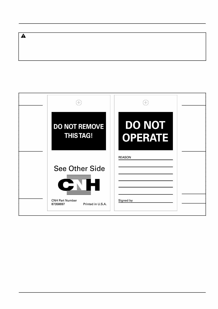
Before you start servicing the machine, attach a DO NOT OPERATE warning tag to the machine in a
visible area.
Failure to comply could result in death or serious injury.
W0004A
Attach a DO NOT OPERATE (TAG) to the machine in an area that is clearly visible whenever the machine is not
operating properly and/or requires service.
Complete the tag information for the "REASON" the tag is attached by describing the malfunction or service required.
Validate the reason for attaching the tag by signing your name in the designated area on the tag.
The tag should only be removed by the person who signed and attached the tag, after validating the repairs or services
have been completed.
(A) (D)
(E)
(B)
(F)
(C)
87358697 1
Tag Components
A. DO NOT REMOVE THIS TAG! - (Warning) The tag should only be removed by the person who signed and
attached the tag, after validating the repairs or services have been completed.
B. See Other Side - (Reference to additional information on opposite side of the tag.)
C. CNH Part Number - (Request this part number from you Service Parts Dealer to obtain this DO NOT OPERATE
tag.)
D. DO NOT OPERATE - (Warning!)
E. REASON - (Area for describing malfunction or service required before operation.)
F. Signed by - (Signature area - to be signed by the person validating the reason for installation of the tag.)
47377943 18/04/2012
3

INTRODUCTION
Safety rules
Personal safety
This is the safety alert symbol. It is used to alert you to potential personal injury hazards. Obey all
safety messages that follow this symbol to avoid possible death or injury.
Throughout this manual and on machine decals, you will find the signal words DANGER, WARNING, and CAUTION
followed by special instructions. These precautions are intended for the personal safety of you and those working
with you.
Read and understand all the safety messages in this manual before you operate or service the machine.
DANGER indicates a hazardous situation which, if not avoided, will result in death or serious injury. The
color associated with DANGER is RED.
WARNING indicates a hazardous situation which, if not avoided, could result in death or serious injury.
The color associated with WARNING is ORANGE.
CAUTION, used with the safety alert symbol, indicates a hazardous situation which, if not avoided, could result
in minor or moderate injury. The color associated with CAUTION is YELLOW.
FAILURE TO FOLLOW DANGER, WARNING, AND CAUTION MESSAGES COULD RESULT
IN DEATH OR SERIOUS INJURY.
Machine safety
NOTICE: Notice indicates a situation which, if not avoided, could result in machine or property damage. The color
associated with Notice is BLUE.
Throughout this manual you will find the signal word Notice followed by special instructions to prevent machine or
property damage. The word Notice is used to address practices not related to personal safety.
Information
NOTE: Note indicates additional information which clarifies steps, procedures, or other information in this manual.
Throughout this manual you will find the word Note followed by additional information about a step, procedure, or
other information in the manual. The word Note is not intended to address personal safety or property damage.
47377943 18/04/2012
4

INTRODUCTION
Safety rules
BT09A213 1
47377943 18/04/2012
5

INTRODUCTION
Basic instructions - Shop and assembly
Shimming
For each adjustment operation, select adjusting shims and measure individually using a micrometer, then add up
the recorded values. Do not rely on measuring the entire shimming set, which may be incorrect, or the rated value
indicated on each shim.
Rotating shaft seals
For correct rotating shaft seal installation, proceed as follows:
•
Before assembly, allow the seal to soak in the oil it will be sealing for at least thirty minutes.
•
Thoroughly clean the shaft and check that the working surface on the shaft is not damaged.
•
Position the sealing lip facing the fluid; with hydrodynamic lips, take into consideration the shaft rotation direction
and position the grooves so that they will deviate the fluid towards the inner side of the seal.
•
Coat the sealing lip with a thin layer of lubricant (use oil rather than grease) and fill the gap between the sealing
lip and the dust lip on double lip seals with grease unless instructed otherwise.
•
Insert the seal in its seat and press down using a flat punch or seal installation tool. Do not tap the seal with a
hammer or mallet.
•
While inserting the seal, check that it is perpendicular to the seat; once settled, make sure that it makes contact
with the thrust element, if required.
•
To prevent damaging the seal lip on the shaft, position a protective guard during installation operations.
O-ring seals
Lubricate the O-ring seals before inserting them in the seats, this will prevent them from overturning and twisting,
which would jeopardize sealing efficiency.
Sealing compounds
Apply one of the following sealing compounds on the mating surfaces when specified: SILMATE® RTV1473, or
LOCTITE® RTV 598 or LOCTITE®INSTANT GASKET 587 BLUE. Before applying the sealing compound, prepare the
surfaces as directed on product container or as follows:
•
Remove any incrustations using a metal brush.
•
Thoroughly de-grease the surfaces using a locally approved cleaning agent such as safety solvent or brake
parts cleaner.
Spare parts
Only use "CNH Original Parts" or " NEW HOLLAND AGRICULTURE Parts".
Only genuine spare parts guarantee the same quality, duration and safety as original parts, as they are the
same parts that are assembled during standard production. Only "CNH Original Parts" or " NEW HOLLAND
AGRICULTURE Parts" can offer this guarantee.
When ordering spare parts, always provide the following information:
•
Machine model (commercial name) and serial number
•
Part number of the ordered part, which can be found in the "Service Parts Catalogue", used for order processing
47377943 18/04/2012
6
You're Reading a Preview
What's Included?
 Lifetime Access
Fast Download Speeds
Online & Offline Access
Access PDF Contents & Bookmarks
Full Search Facility
Print one or all pages of your manual
$77.99
New Holland Guardian SP.240R, Guardian SP.275R Service Manual
Viewed 52 Times Today

What's Included?
Lifetime Access
Fast Download Speeds
Online & Offline Access
Access PDF Contents & Bookmarks
Full Search Facility
Print one or all pages of your manual
$77.99

Secure transaction
What's Included?
Lifetime Access
Fast Download Speeds
Online & Offline Access
Access PDF Contents & Bookmarks
Full Search Facility
Print one or all pages of your manual
- The New Holland Guardian SP.240R, Guardian SP.275R Sprayers Repair Manual is a comprehensive guide for maintaining and repairing these powerful sprayers.
- It is suitable for both professional technicians and do-it-yourself enthusiasts, providing all the necessary information to keep the sprayers in top shape.
- Inside, you'll find a detailed workshop manual covering all aspects of repair and maintenance, including step-by-step instructions and illustrations for tasks ranging from basic removal and installation to more complex disassembly and assembly procedures.
- In addition to the workshop manual, this repair manual also includes an electrical wiring diagram and a hydraulic schematic, essential for troubleshooting electrical and hydraulic issues.
- The diagnostic section offers valuable information and guidance for identifying and resolving common issues, enabling users to save time and money by diagnosing and fixing problems independently.
- Detailed specifications and torque values are also included, providing all the necessary information for performing repairs and maintenance tasks effectively.


