


Part number 84425026
2nd edition English
April 2011
Replaces part number 87492450
SERVICE MANUAL
P2070
Precision Air Hoe Drill

Contents
INTRODUCTION
HYDRAULIC, PNEUMATIC, ELECTRICAL, ELECTRONIC SYSTEMS A
PRIMARY HYDRAULIC POWER SYSTEM .............................................. A.10.A
LIGHTING SYSTEM...................................................................... A.40.A
ELECTRONIC SYSTEM ................................................................. A.50.A
FAULT CODES ........................................................................... A.50.A
AXLES, BRAKES AND STEERING................................................. D
FRONT AXLE ............................................................................ D.10.A
WHEELS AND TRACKS Wheels......................................................... D.50.C
FRAME AND CAB ........................................................................ E
FRAME Primary frame ................................................................... E.10.B
FRAME POSITIONING ................................................................. F
TRAVELLING Folding .................................................................... F.10.E
FRAME LEVELLING ..................................................................... F.30.A
FIELD PROCESSING ................................................................... L
SEEDING Mechanical system............................................................ L.10.B
SEEDING Electronic system ............................................................. L.10.C
SEEDING Air system ..................................................................... L.10.E
SOIL PREPARATION Planting ........................................................... L.50.D
84425026 11/04/2011

INTRODUCTION
84425026 11/04/2011
1

Contents
INTRODUCTION
Advice ........................................................................................... 3
Foreword ........................................................................................ 4
FRAME - Safety signs .......................................................................... 8
Basic instructions ............................................................................. 16
Torque ........................................................................................ 18
Torque – Hydraulic Tubes and Fittings ........................................................ 20
Dimension .................................................................................... 21
Weight ........................................................................................ 23
Product identification .......................................................................... 24
Product identification .......................................................................... 25
84425026 11/04/2011
2

INTRODUCTION
Advice
All repair and maintenance works listed in this manual must be carried out only by qualified dealership personnel,
strictly complying with the instructions given; and using, whenever possible, the special tools.
Anyone who carries out the above operations without complying with the procedures shall be responsible for the
subsequent damages.
The manufacturer and all the organizations of it’s distribution chain, including - without limitation - national, regional,
or local dealers, reject any responsibility for damages due to the anomalous behavior of parts and/or components not
approved by the manufacturer himself, including those used for the servicing or repair of the product manufactured
or marketed by the manufacturer. In any case, no warranty is given or attributed on the product manufactured or
marketed by the manufacturer in case of damages due to an anomalous behavior or parts and/or components not
approved by the manufacturer.
The information in this manual is up-to-date at the date of the publication. It is the policy of the manufacturer for
continuous improvement. Some information could not be updated due to modifications of a technical or commercial
type, as well as to suit the law regulations of different countries.
In case of disagreement, refer to your Sales and Service Networks.
84425026 11/04/2011
3

INTRODUCTION
Foreword
Technical Information and ICE
This information in this manual has been structured using the Integrated Coding Environment (ICE). ICE is the way
in which technical information is created, stored and retrieved in the Technical Information Database.
ICE coding classifies all information in three ways.
The first category is the Location, the second category is the Information Type and the third category is the Product:
•
LOCATION - is the component, or function on the machine, that the piece of technical information is going to
describe e.g. Fuel tank.
•
INFORMATION TYPE - is the piece of technical information that has been written for a particular component or
function on the machine. e.g., Capacity would be a type of Technical Data that would describe the amount of fuel
held by the Fuel tank.
•
PRODUCT - is the model that the piece of technical information is written for. e.g.,
Every piece of technical information will have those 3 categories attached to it. You will be able to use any combination
of those categories to find the right piece of technical information you need to resolve that customers concern on his
machine.
That information could be:
•
the description of how to remove the cylinder head
•
a table of specifications for a hydraulic pump
•
a fault code
•
a troubleshooting table
•
a special tool
How to Use this Manual
This manual is divided into Sections. Each Section is then divided into Chapters. Contents pages are included at the
beginning of the manual, then inside every Section and inside every Chapter. An alphabetical Index is included at the
end of a Chapter. Page number references are included for every piece of technical information listed in the Chapter
Contents or Chapter Index.
Each Chapter is divided into four Information types:
•
Technical Data (specifications) for all the mechanical, electrical, or hydraulic devices, components, and assem-
blies.
•
Functional Data (how it works) for all the mechanical, electrical, or hydraulic devices, components, and assem-
blies.
•
Diagnostic Data (fault codes, electrical and hydraulic troubleshooting) for all the mechanical, electrical, or hydraulic
devices, components, and assemblies.
•
Service data (remove, disassemble, assemble, install) for all the mechanical, electrical, or hydraulic devices, com-
ponents, and assemblies.
Sections
Sections are grouped according to the main functions or systems on the machine. Each Section is identified by a letter
A, B, C etc. The number of Sections included in the manual will depend on the type and function of the machine that
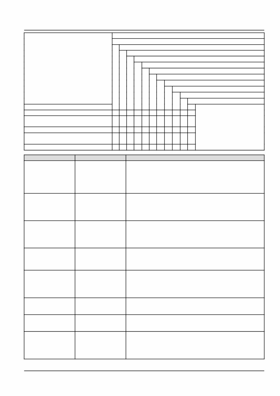
the manual is written for. Each Section has a Contents page listed in alphabetic/numeric order. This table illustrates
which Sections could be included in a manual for a particular product.
84425026 11/04/2011
4
INTRODUCTION
SECTION
A - Hydraulic, Pneumatic, Electrical, Electronic Systems
B - Power Production
C - Power Train
D - Travelling
E - Body and Structure
F - Frame Positioning
G - Tool Positioning
H - Working Arm
J - Tools and Couplers
K - Crop Processing
L - Field Processing
PRODUCT
Tractors X X X X X X X X
Vehicles with working arms: backhoes,
excavators, skid steers, ....
X X X X X X X X X
Combines, forage harvesters, balers, ... X X X X X X X X
Seeding, planting, floating, spraying
equipment, ...
X X X X X X X X X
Mounted equipment and tools, .... X X X X
SECTION LETTER DESCRIPTION
HYDRAULIC,
PNEUMATIC,
ELECTRICAL
ELECTRONIC
SYSTEMS
A This Section covers the main systems that interact with most of
the functions of the product. It includes the central parts of the
hydraulic, electrical, electronic, pneumatic, lighting and grease
lubrication systems. The components that are dedicated to a
specific function are listed in the Chapter where all the technical
information for that function is included.
POWER
PRODUCTION
B This Section covers all the functions related to the production
of power to move the machine and to drive various devices.
In the case of a pulled-type machine, this Section covers the
power take-off function where power is provided from the towing
machine.
POWER TRAIN C This Section covers all the functions related to the transmission
of power from the engine to the axles and to internal or external
devices. This Section also covers the power take-off function
where power is provided to the pull-type machine and additional
Process Drive functions.
TRAVELLING D This Section covers all the functions related to moving the
machine, including tracks, wheels, steering and braking. It covers
all the axles; both driven axles and non-driven axles, including
any axle suspension.
BODY AND
STRUCTURE
E This Section covers all the main functions and systems related to
the structure and the body of the machine, including the frame,
the shields, the operators cab and the platform. The functions
related to the positioning of the machine frame are included in
Section F, Frame Positioning.
FRAME POSITIONING F This Section covers all the main functions and systems related to
positioning of the machine frame or to positioning the attachment
on the supporting machine frame.
TOOL POSITIONING G This Section covers all the functions related to the final and/or
automatic positioning of the tool once the tool is positioned using
the Working Arm or the machine frame.
WORKING ARM H This Section covers all the functions related to the articulated
or single arms mounted on the front or rear of the machine. A
working arm can have various tools and quick couplers mounted
on to it. The tools and quick couplers are included in Section
J, Tools and Couplers.
84425026 11/04/2011
5

INTRODUCTION
SECTION LETTER DESCRIPTION
TOOLS AND
COUPLERS
J This Section covers all the functions related to the specific tools
that mount on the front, rear or beside the machine. The tools
described here can be mounted with the positioning systems
(lifting, side shift, swing) listed in Section G Tool Positioning. This
Section covers all the quick coupling systems, located between
the tool and the positioning system. The tools used for field
preparation, soil preparation and treatment, planting and seeding
are included.
CROP PROCESSING K This Section covers all the functions related to crop processing.
Examples of crop processing include threshing, baling,
windrowing, cutting and conditioning.
FIELD PROCESSING L This Section covers all the field processing functions of the
machine. Examples of field process include seeding, fertilizer
application, seedbed preparation and chemical application.
This manual contains these sections.
Contents
INTRODUCTION
HYDRAULIC, PNEUMATIC, ELECTRICAL ELECTRONIC SYSTEMS A
TRAVELLING D
BODY AND STRUCTURE E
FRAME POSITIONING F
FIELD PROCESSING L
Your manual contains these Sections. The contents of each Section are explained over the following pages.
Section Contents
SECTION A, HYDRAULIC, PNEUMATIC, ELECTRICAL ELECTRONIC SYSTEMS
SECTION D, TRAVELLING
SECTION E, BODY AND STRUCTURE
SECTION F, FRAME POSITIONING
SECTION L, FIELD PROCESSING
Chapters
Each Chapter is identified by a letter and number combination e.g. Seeding L.10.B. The first letter is identical to the
Section letter i.e. Chapter L.10.B is inside Section L, Field Processing. The Chapter Contents lists all the "Technical
Data" (specifications), "Functional Data" (how it works), "Service Data" (remove, install, adjust, etc.,) and "Diagnostic
Data" (fault codes and troubleshooting) that have been written in that Chapter for that function or system on the
machine.
The Chapter Index lists in alphabetical order all the types of information (called Information Units) that have been
written in that Chapter for that function or system on the machine.
Information Units and Information Search
Each chapter is composed of information units. The ICE coding is not included in the Information Unit title.
Page Header and Footer
The page header will contain the following references:
•
Section and Chapter description
The page footer will contain the following references.
84425026 11/04/2011
6

INTRODUCTION
Printed references found at the base of each page then equate to
•
The publication number for that Manual, Section, or Chapter
•
Revision number of the publication
•
Publication date
•
Chapter reference (n/a)
•
Page number
84425026 11/04/2011
7
INTRODUCTION
FRAME - Safety signs
KEEP SAFETY DECALS CLEAN.
Wipe clean when necessary.
REPLACE missing or unreadable decals. New decals are
available from your dealer.
To replace decals:
1. Remove old decal and clean area.
2. Remove the decal backing and carefully affix the decal
to the implement.
3. Using a clean piece of paper or the backing itself, work
the air bubbles out from under the decal.
209154C 1
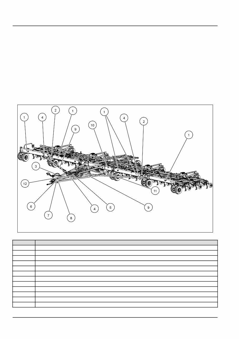
REF Decal Description
(1) DANGER- Keep clear of machine
(2) WARNING - Drill may become unstable
(3) Read your Operator’s Manual
(4) DANGER - Stay out of fold zone
(5) DANGER - Rollover hazard
(6) Do not ride.
(7) CAUTION - Escaping fluid hazard
(8) DANGER - Hitch upending hazard
(9) IMPORTANT - Latches must be engaged
(10) ATTENTION - To avoid unnecessary frame loading
(11) CAUTION - Unauthorized removal of this decal will void warranty
(12) WARNING - Hydraulic accumulator contains gas and oil under pressure.
84425026 11/04/2011
8
You're Reading a Preview
What's Included?
 Lifetime Access
Fast Download Speeds
Online & Offline Access
Access PDF Contents & Bookmarks
Full Search Facility
Print one or all pages of your manual
$128.99
New Holland P2070 Service Manual
Viewed 33 Times Today

What's Included?
Lifetime Access
Fast Download Speeds
Online & Offline Access
Access PDF Contents & Bookmarks
Full Search Facility
Print one or all pages of your manual
$128.99

Secure transaction
What's Included?
Lifetime Access
Fast Download Speeds
Online & Offline Access
Access PDF Contents & Bookmarks
Full Search Facility
Print one or all pages of your manual
Description
The New Holland P2070 Planting/Seeding Repair Manual is a comprehensive guide for maintaining and repairing equipment. It offers detailed instructions for removal, installation, disassembly, and assembly, making it valuable for both professional mechanics and DIY enthusiasts.
It includes an electrical wiring diagram and hydraulic schematic to assist in troubleshooting and diagnosing issues. Additionally, the manual provides specifications and torque values for ensuring proper installation and optimal operation of every component.
Models included in this repair manual:
- New Holland P2070


