


Flex Air 810
Applicator
from PIN YCT033001 and above
Part number 84588406
1st edition English
July 2012
SERVICE MANUAL

Contents
INTRODUCTION
Transmission.............................................................................. 21
Drop box .................................................................................. 21.200
Hydraulic systems....................................................................... 35
Hydraulic systems ........................................................................ 35.000
Fixed displacement pump ................................................................ 35.104
Variable displacement pump ............................................................. 35.106
Granular chemical hydraulic fan system ................................................. 35.749
Pneumatic system ...................................................................... 36
Pneumatic system ........................................................................ 36.100
Electrical systems ....................................................................... 55
Harnesses and connectors ............................................................... 55.100
Application fertilizer control ............................................................... 55.636
Chemical applicators ................................................................... 63
Granular chemical system ................................................................ 63.110
Spraying .................................................................................... 78
Spraying pump ........................................................................... 78.111
84588406 12/07/2012

INTRODUCTION
84588406 12/07/2012
1

Contents
INTRODUCTION
Personal safety - Do not operate tag ........................................................... 3
Flex-Air 810
Personal safety - Signal words ................................................................. 4
Flex-Air 810
Personal safety - California Proposition 65 Warning ........................................... 5
Flex-Air 810
Basic instructions - Shop and assembly ........................................................ 6
Flex-Air 810
Torque - Minimum tightening torques for normal assembly ..................................... 8
Flex-Air 810
Torque - Standard torque data for hydraulics ................................................. 13
Flex-Air 810
Maintenance Chart ............................................................................ 15
Flex-Air 810
Definition - Important notice regarding equipment servicing .................................. 16
Flex-Air 810
Product identification - Fuse and relay locations ............................................. 17
Flex-Air 810
84588406 12/07/2012
2
INTRODUCTION
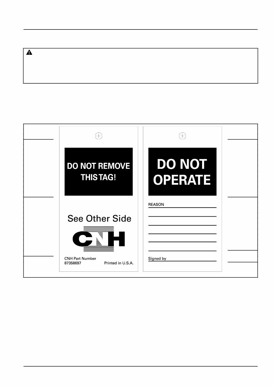
Personal safety - Do not operate tag
Flex-Air 810
WARNING
Maintenance hazard!
Before you start servicing the machine, attach a DO NOT OPERATE warning tag to the machine in a
visible area.
Failure to comply could result in death or serious injury.
W0004A
Attach a DO NOT OPERATE (TAG) to the machine in an area that is clearly visible whenever the machine is not
operating properly and/or requires service.
Complete the tag information for the "REASON" the tag is attached by describing the malfunction or service required.
Validate the reason for attaching the tag by signing your name in the designated area on the tag.
The tag should only be removed by the person who signed and attached the tag, after validating the repairs or services
have been completed.
(A) (D)
(E)
(B)
(F)
(C)
87358697 1
Tag Components
A. DO NOT REMOVE THIS TAG! - (Warning) The tag should only be removed by the person who signed and
attached the tag, after validating the repairs or services have been completed.
B. See Other Side - (Reference to additional information on opposite side of the tag.)
C. CNH Part Number - (Request this part number from you Service Parts Dealer to obtain this DO NOT OPERATE
tag.)
D. DO NOT OPERATE - (Warning!)
E. REASON - (Area for describing malfunction or service required before operation.)
F. Signed by - (Signature area - to be signed by the person validating the reason for installation of the tag.)
84588406 12/07/2012
3
INTRODUCTION
Personal safety - Signal words
Flex-Air 810
Personal safety
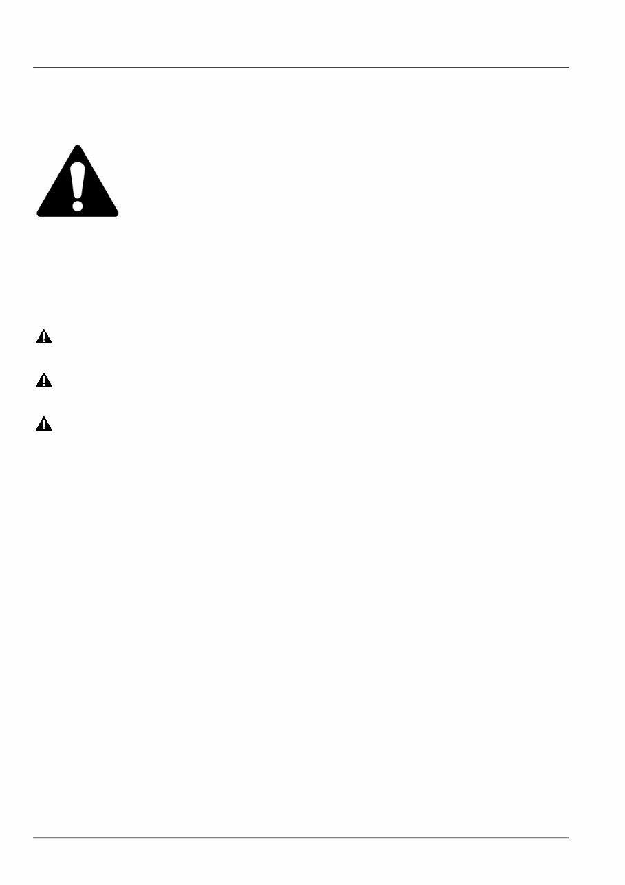
This is the safety alert symbol. It is used to alert you to potential personal injury hazards. Obey all
safety messages that follow this symbol to avoid possible death or injury.
Throughout this manual and on machine decals, you will find the signal words DANGER, WARNING, and CAUTION
followed by special instructions. These precautions are intended for the personal safety of you and those working
with you.
Read and understand all the safety messages in this manual before you operate or service the machine.
DANGER indicates a hazardous situation which, if not avoided, will result in death or serious injury. The
color associated with DANGER is RED.
WARNING indicates a hazardous situation which, if not avoided, could result in death or serious injury.
The color associated with WARNING is ORANGE.
CAUTION, used with the safety alert symbol, indicates a hazardous situation which, if not avoided, could result
in minor or moderate injury. The color associated with CAUTION is YELLOW.
FAILURE TO FOLLOW DANGER, WARNING, AND CAUTION MESSAGES COULD RESULT
IN DEATH OR SERIOUS INJURY.
Machine safety
NOTICE: Notice indicates a situation which, if not avoided, could result in machine or property damage. The color
associated with Notice is BLUE.
Throughout this manual you will find the signal word Notice followed by special instructions to prevent machine or
property damage. The word Notice is used to address practices not related to personal safety.
Information
NOTE: Note indicates additional information which clarifies steps, procedures, or other information in this manual.
Throughout this manual you will find the word Note followed by additional information about a step, procedure, or
other information in the manual. The word Note is not intended to address personal safety or property damage.
84588406 12/07/2012
4
INTRODUCTION
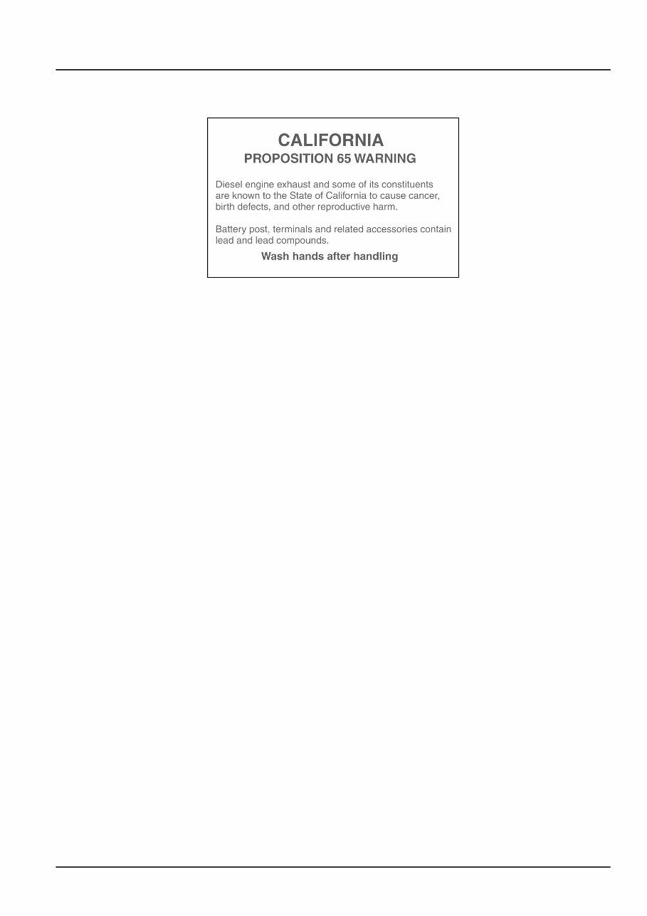
Personal safety - California Proposition 65 Warning
Flex-Air 810
BT09A213 1
84588406 12/07/2012
5

INTRODUCTION
Basic instructions - Shop and assembly
Flex-Air 810
Shimming
For each adjustment operation, select adjusting shims and measure individually using a micrometer, then add up
the recorded values. Do not rely on measuring the entire shimming set, which may be incorrect, or the rated value
indicated on each shim.
Rotating shaft seals
For correct rotating shaft seal installation, proceed as follows:
•
Before assembly, allow the seal to soak in the oil it will be sealing for at least thirty minutes.
•
Thoroughly clean the shaft and check that the working surface on the shaft is not damaged.
•
Position the sealing lip facing the fluid; with hydrodynamic lips, take into consideration the shaft rotation direction
and position the grooves so that they will deviate the fluid towards the inner side of the seal.
•
Coat the sealing lip with a thin layer of lubricant (use oil rather than grease) and fill the gap between the sealing
lip and the dust lip on double lip seals with grease unless instructed otherwise.
•
Insert the seal in its seat and press down using a flat punch or seal installation tool. Do not tap the seal with a
hammer or mallet.
•
While inserting the seal, check that it is perpendicular to the seat; once settled, make sure that it makes contact
with the thrust element, if required.
•
To prevent damaging the seal lip on the shaft, position a protective guard during installation operations.
O-ring seals
Lubricate the O-ring seals before inserting them in the seats, this will prevent them from overturning and twisting,
which would jeopardize sealing efficiency.
Sealing compounds
Apply one of the following sealing compounds on the mating surfaces when specified: SILMATE® RTV1473, or
LOCTITE® RTV 598 or LOCTITE®INSTANT GASKET 587 BLUE. Before applying the sealing compound, prepare the
surfaces as directed on product container or as follows:
•
Remove any incrustations using a metal brush.
•
Thoroughly de-grease the surfaces using a locally approved cleaning agent such as safety solvent or brake
parts cleaner.
Spare parts
Only use "CNH Original Parts" or " CASE IH AGRICULTURE Parts".
Only genuine spare parts guarantee the same quality, duration and safety as original parts, as they are the same
parts that are assembled during standard production. Only "CNH Original Parts" or " CASE IH AGRICULTURE
Parts" can offer this guarantee.
When ordering spare parts, always provide the following information:
•
Machine model (commercial name) and serial number
•
Part number of the ordered part, which can be found in the "Service Parts Catalogue", used for order processing
84588406 12/07/2012
6

INTRODUCTION
Protecting the electrical/electronic systems during charging or welding
WARNING
Battery acid causes burns. Batteries contain sulfuric acid.
Avoid contact with skin, eyes or clothing. Antidote (external): Flush with water. Antidote (eyes): flush
with water for 15 minutes and seek medical attention immediately. Antidote (internal): Drink large
quantities of water or milk. Do not induce vomiting. Seek medical attention immediately.
Failure to comply could result in death or serious injury.
W0111A
To avoid damage to the electronic/electrical systems, always observe the following:
1. Never make or break any of the charging circuit connections, including the battery connections, when the engine
is running.
2. Never short any of the charging components to ground.
3. Always disconnect the ground cable from the battery before arc welding on the machine or on any attachments
on the machine.
•
Position the welder ground clamp as close to the welding area as possible
•
If welding in close proximity to a computer module, then the module should be removed from the machine
•
Never allow welding cables to lay on, near or across any electrical wiring or electronic component while
welding is in progress
4. Always disconnect the negative cable from the battery when charging the battery in the machine with a battery
charger.
NOTICE: If welding must be performed on the unit, the battery ground cable must be disconnected from the machine
battery. The electronic monitoring system and charging system will be damaged if this is not done.
Remove the battery ground cable. Reconnect the cable when welding is completed.
Tools
The tools that CASE IH AGRICULTURE suggests and illustrated in this manual have been:
•
Specifically researched and designed for use with CASE IH AGRICULTURE machines
•
Essential for reliable repair operations
•
Accurately built and rigorously tested so as to offer efficient and long-lasting operation
By using these tools, repair personnel will benefit from:
•
Operating in optimal technical conditions
•
Obtaining the best results
•
Saving time and effort
•
Working in safe conditions
NOTE: The terms "front", "rear", "right-hand" and "left-hand" (when referred to different parts) are determined from
the rear, facing in the direction of travel of the machine during operation.
84588406 12/07/2012
7
INTRODUCTION
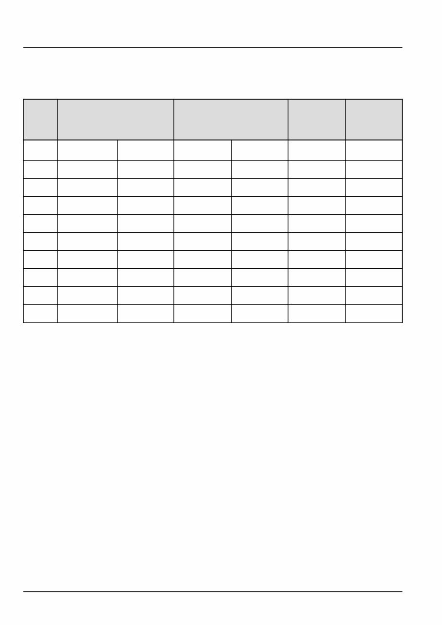
Torque - Minimum tightening torques for normal assembly
Flex-Air 810
METRIC NON-FLANGED HARDWARE
NOM.
SIZE
CLASS 8.8 BOLT and
CLASS 8 NUT
CLASS 10.9 BOLT and
CLASS 10 NUT
LOCKNUT
CL.8
W/CL8.8
BOLT
LOCKNUT
CL.10
W/CL10.9
BOLT
UNPLATED
PLATED
W/ZnCr
UNPLATED
PLATED
W/ZnCr
M4
2.2 N·m (19 lb
in)
2.9 N·m (26 lb
in)
3.2 N·m (28 lb
in)
4.2 N·m (37 lb
in)
2 N·m (18 lb in)
2.9 N·m (26 lb
in)
M5
4.5 N·m (40 lb
in)
5.9 N·m (52 lb
in)
6.4 N·m (57 lb
in)
8.5 N·m (75 lb
in)
4 N·m (36 lb in)
5.8 N·m (51 lb
in)
M6
7.5 N·m (66 lb
in)
10 N·m (89 lb
in)
11 N·m (96 lb
in)
15 N·m (128 lb
in)
6.8 N·m (60 lb
in)
10 N·m (89 lb
in)
M8
18 N·m (163 lb
in)
25 N·m (217 lb
in)
26 N·m (234 lb
in)
35 N·m (311 lb
in)
17 N·m (151 lb
in)
24 N·m (212 lb
in)
M10 37 N·m (27 lb ft)
49 N·m (36 lb
ft)
52 N·m (38 lb ft)
70 N·m (51 lb
ft)
33 N·m (25 lb
ft)
48 N·m (35 lb
ft)
M12 64 N·m (47 lb ft)
85 N·m (63 lb
ft)
91 N·m (67 lb ft)
121 N·m (90 lb
ft)
58 N·m (43 lb
ft)
83 N·m (61 lb
ft)
M16
158 N·m (116 lb
ft)
210 N·m (155
lb ft)
225 N·m (166 lb
ft)
301 N·m (222
lb ft)
143 N·m (106 lb
ft)
205 N·m (151 lb
ft)
M20
319 N·m (235 lb
ft)
425 N·m (313
lb ft)
440 N·m (325 lb
ft)
587 N·m (433
lb ft)
290 N·m (214 lb
ft)
400 N·m (295 lb
ft)
M24
551 N·m (410 lb
ft)
735 N·m (500
lb ft)
762 N·m (560 lb
ft)
1016 N·m (750
lb ft)
501 N·m (370 lb
ft)
693 N·m (510 lb
ft)
NOTE: M4 through M8 hardware torque specifications are shown in pound-inches. M10 through M24 hardware torque
specifications are shown in pound-feet.
84588406 12/07/2012
8
You're Reading a Preview
What's Included?
 Lifetime Access
Fast Download Speeds
Online & Offline Access
Access PDF Contents & Bookmarks
Full Search Facility
Print one or all pages of your manual
$94.99
Case IH Flex Air 810 Service Manual
Viewed 15 Times Today

What's Included?
Lifetime Access
Fast Download Speeds
Online & Offline Access
Access PDF Contents & Bookmarks
Full Search Facility
Print one or all pages of your manual
$94.99

Secure transaction
What's Included?
Lifetime Access
Fast Download Speeds
Online & Offline Access
Access PDF Contents & Bookmarks
Full Search Facility
Print one or all pages of your manual
Description
The Case IH Flex Air 810 Planting/Seeding Repair Manual is a comprehensive guide suitable for both professional mechanics and DIY enthusiasts. It provides detailed instructions for removal, installation, disassembly, and assembly procedures, along with electrical wiring diagrams and hydraulic schematics to aid in understanding the equipment's systems.
Additionally, the manual offers diagnostic information for issue identification and troubleshooting. The specification and torque values section ensures the correct information for proper assembly and operation of the equipment.
Models included in this manual:
- Case IH Flex Air 810


