G E H L: COMPANY New Agricultural Equipment G E H L: Company (Inc.), hereinafter referred to as G E H L:, warrants new G E H L: machinery and attach- ments (the "Equipment") to be free from defects in material and workmanship at thetime of delivery to the original purchaser if properly set up and operated in accordance with the recommendations set forth in G E H L: 's Operator's Manual. G E H L: 's liability for any defect shall be limited to repair or replacement of the Equipment. G E H L: 's obligation shall terminate twelve (12) months after the delivery of the goods to the original retail purchaser or when the Equipment is first put into use, whichever event occurs first. This warranty shall not apply to tires whic'h are subject to the warranty of the tire manufacturer. Please contact your G E H L: dealer for further information on tire warranties. This warranty shall not apply to any item of Equipment which shall have been repaired or altered outside the G E H L: factory or authorized G E H L: dealership or which has been subject to misuse, negligence or accident; neither shall it apply to Equipment which has not been operated in accordance with G E H L: 's printed instructions or has been operated beyond the Company's recommended machine rated capacity. EXCLUSION OF WARRANTIES Except as otherwise expressly stated herein, G E H L: makes no representation or warranty of any kind, express or implied, including merchantability or fitness for particular purpose in respect to the Equipment. G E H L: shall not be liable for incidental or consequential damages for any breach of warranty, including but not limited to inconvenience, rental or replacement equipment, loss of profits or other commercial loss. No agent, employee or representative of G E H L: has any authority to bind G E H L: to any affirmation, representation or warranty concerning its machinery and attachments except as specifically set forth herein. Certain limitations expressed herein are excludable in accordance with provisions of local law. Such provisions shall be deemed struck if such local law is applicable. All other provisions shall continue to apply. G E H l..; COMPANY New Agricultural Equipment G E H l..; Company (Inc.), hereinafter referred to aSG E H l..;, warrants new G E H l..; machinery and attach- ments (the "Equipment") to be free from defects in material and workmanship at the time of delivery to the original purchaser if properly set up and operated in accordance with the recommendations set forth in G E H l..;'S Operator's Manual. G E H l..; 's liability for any defect shall be limited to repair or replacement of the Equipment. G E H l..; 's obligation shall terminate twelve (12) months after the delivery of the goods to the original retail purchaser or when the Equipment is first put into use, whichever event occurs first. This warranty shall not apply to tires which are subject to the warranty of the tire manufacturer. Please contact your G E H l..; dealer for further information on tire warranties. This warranty shall not apply to any item of Equipment which shall have been repaired or altered outside the G E H l..; factory or authorized G E H l..; dealership or which has been subject to misuse, negligence or accident; neither shall it apply to Equipment which has not been operated in accordance with G E H l..; 's printed instructions or has been operated beyond the Company's recommended machine rated capacity. EXCLUSION OF WARRANTIES Except as otherwise expressly stated herein, G E H l..; makes no representation or warranty of any kind, express or implied, including merchantability or fitness for particular purpose in respect to the Equipment. G E H l..; shall not be liable for incidental or consequential damages for any breach of warranty, including but not limited to inconvenience, rental or replacement equipment, loss of profits or other commercial loss. No agent, employee or representative of G E H l..; has any authority to bind G E H l..; to any affirmation, representation or warranty concerning its machinery and attachments except as specifically set forth herein. Certain limitations expressed herein are excludable in accordance with provisions of local law. Such provisions shall be deemed struck if such local law is applicable. All other provisions shall continue to apply.
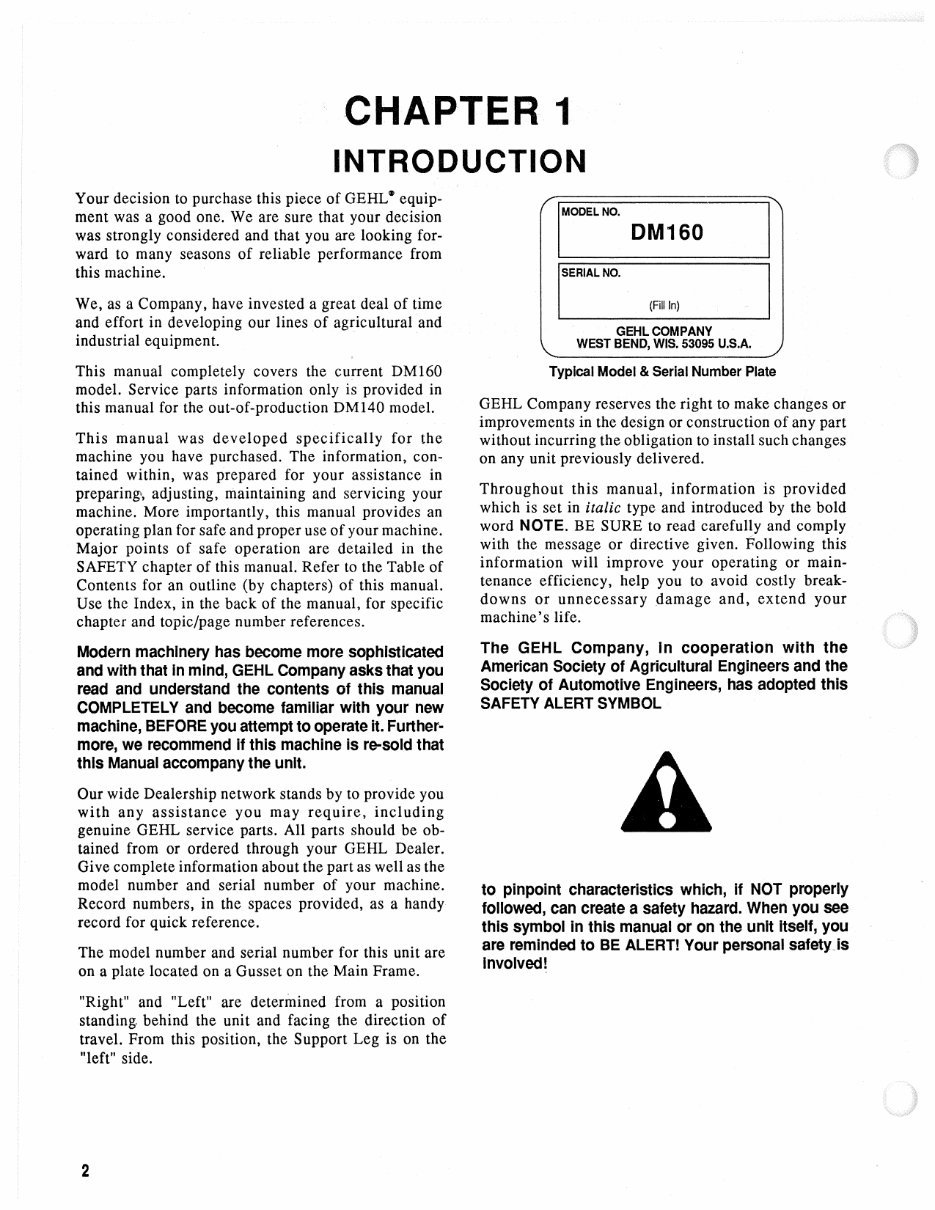
·CHAPTER 1 INTRODUCTION Your decision to purchase this piece of GEHL \9 equip- ment was a good one. We are sure that your decision was strongly considered and that you are looking for- ward to many seasons of reliable performance from this machine. We, as a Company, have invested a great deal of time and effort in developing our lines of agricultural and industrial equipment. . This manual completely covers the current DM160 model. Service parts information only is provided in this manual for the out-of-production DM140 model. This manual was developed specifically for the machine you have purchased. The information, con- tained within, was prepared for your assistance in preparing', adjusting, maintaining and servicing your machine. More importantly, this manual provides an operating plan for safe and proper use of your machine. Major points of safe operation are detailed in the SAFETY chapter of this manual. Refer to the Table of Contents for an outline (by chapters) of this manual. Use the Index, in the back of the manual, for specific chapter and topic/page number references. Modern machinery has become more sophisticated and with that In mind, GEHL Company asks that you read and understand the contents of this manual COMPLETELY and become familiar with your new machine, BEFORE you attempt to operate it. Further- more, we recommend if this machine is re-sold that this Manual accompany the unit. Our wide Dealership network stands by to provide you with any assistance you may require, including genuine GEHL service parts. All parts should be ob- tained from or ordered through your GEHL Dealer. Give complete information about the part as well as the model number and serial number of your machine. Record numbers, in the spaces provided, as a handy record for quick reference. The model number and serial number for this unit are on a plate located on a Gusset on the Main Frame. "Right" and "Left" are determined from a position standing behind the unit and facing the direction of travel. From this position, the Support Leg is on the "left" side. 2 IMODELNO. DM160 SERIAL NO. (Fill In) GEHLCOMPANY WEST BEND, WIS. 53095 U.S.A. Typical Model & Serial Number Plate GEHL Company reserves the right to make changes or improvements in the design or construction of any part without incurring the obligation to install such changes on any unit previously delivered. Throughout this manual, information is provided which is set in italic type and introduced by the bold word NOTE. BE SURE to read carefully and comply with the message or directive given. Following this information will improve your operating or main- tenance efficiency, help you to avoid costly break- downs or unnecessary damage and, extend your machine's life. The GEHL Company, In cooperation with the American Society of Agricultural Engineers and the Society of Automotive Engineers, has adopted this SAFETY ALERT SYMBOL A to pinpoint characteristics which, If NOT properly followed, can create a safety hazard. When you see this symbol in this manual or on the unit itself, you are reminded to BE ALERTI Your personal safetyJs Involved I
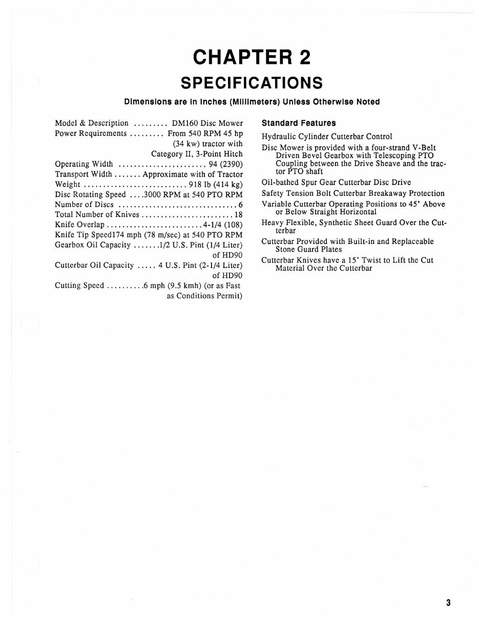
CHAPTER 2 SPECIFICATIONS Dimensions are In Inches (Millimeters) Unless Otherwise Noted Model & Description ......... DM160 Disc Mower Power Requirements ... . . . . .. From 540 RPM 45 hp (34 kw) tractor with Category II, 3-Point Hitch Operating Width ....................... 94 (2390) Transport Width ....... Approximate with of Tractor Weight ........................... 918 lb (414 kg) Disc Rotating Speed .... 3000 RPM at 540 PTO RPM Number of Discs ............................... 6 Total Number of Knives ........................ 18 Knife Overlap ......................... 4-1/4 (l08) Knife Tip Speed174 mph (78 m/sec) at 540 PTO RPM Gearbox Oil Capacity ....... 1/2 U.S. Pint (1/4 Liter) ofHD90 Cutterbar Oil Capacity ..... 4 U.S. Pint (2-1/4 Liter) of HD90 Cutting Speed .......... 6 mph (9.5 kmh) (or as Fast as Conditions Permit) Standard Features Hydraulic Cylinder Cutterbar Control Disc Mower is provided with a four-strand V-Belt Driven Bevel Gearbox with Telescoping PTO Coupling between the Drive Sheave and the trac- tor PTO shaft Oil-bathed Spur Gear Cutterbar Disc Drive Safety Tension Bolt Cutterbar Breakaway Protection Variable Cutterbar Operating Positions to 45° Above or Below Straight Horizontal . Heavy Flexible, Synthetic Sheet Guard Over the Cut- terbar Cutterbar Provided with Built-in and Replaceable Stone Guard Plates Cutterbar Knives have a 15° Twist to Lift the Cut Material Over the Cutterbar 3 CHAPTER 2 SPECIFICATIONS Dimensions are In Inches (Millimeters) Unless Otherwise Noted Model & Description ......... DM160 Disc Mower Power Requirements ... . . . . .. From 540 RPM 45 hp (34 kw) tractor with Category II, 3-Point Hitch Operating Width ....................... 94 (2390) Transport Width ....... Approximate with of Tractor Weight ........................... 918 lb (414 kg) Disc Rotating Speed .... 3000 RPM at 540 PTO RPM Number of Discs ............................... 6 Total Number of Knives ........................ 18 Knife Overlap ......................... 4-1/4 (l08) Knife Tip Speed174 mph (78 m/sec) at 540 PTO RPM Gearbox Oil Capacity ....... 1/2 U.S. Pint (1/4 Liter) ofHD90 Cutterbar Oil Capacity ..... 4 U.S. Pint (2-1/4 Liter) of HD90 Cutting Speed .......... 6 mph (9.5 kmh) (or as Fast as Conditions Permit) Standard Features Hydraulic Cylinder Cutterbar Control Disc Mower is provided with a four-strand V-Belt Driven Bevel Gearbox with Telescoping PTO Coupling between the Drive Sheave and the trac- tor PTO shaft Oil-bathed Spur Gear Cutterbar Disc Drive Safety Tension Bolt Cutterbar Breakaway Protection Variable Cutterbar Operating Positions to 45° Above or Below Straight Horizontal . Heavy Flexible, Synthetic Sheet Guard Over the Cut- terbar Cutterbar Provided with Built-in and Replaceable Stone Guard Plates Cutterbar Knives have a 15° Twist to Lift the Cut Material Over the Cutterbar 3
INTENTIONALLY BLANK 4 INTENTIONALLY BLANK 4
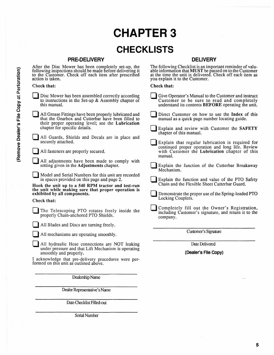
- c o o t: CD Il. 'to >- c. o o .! u:: U) i.. CD 1;; CD C E CD a: - CHAPTER 3 CHECKLISTS PRE-DEUVERY After the Disc Mower has been completely set-up, the following inspections should be made Defore delivering it to the Customer. Check off each item after prescrioed action is taken. Check that: D Disc Mower has been assembled correctly according to instructions in the Set-up & Assembly chapter of this manual. D All Grease Fittings have been properly lubricated and that the Gearbox and Cutterbar have been filled to their proper operating level; see the Lubrication chapter for specific details. D All Guards, Shields and Decals are in place and securely attached. D All fasteners are properly secured. D All adjustments have been made to comply with setting given in the Adjustments chapter. D Model and Serial Numbers for this unit are recorded in spaces provided on this page and page 2. Hook the unit up to a 540 RPM tractor and test-run the unit while making sure that proper operation is exhibited by all components. Check that: D The Telescoping PTO rotates freely inside the properly Chain-anchored PTO Shields. D All Blades and Discs are turning freely. D All mechanisms are operating smoothly. D All hydraulic Hose connections are NOT leaking under pressure and that Lift Mechanism is operating smoothly and properly. I acknowledge that pre-delivery procedures were per- formed on thIS unit as outlined above. Dealership Name Dealer Represenlative's Name Date Checklist FIlled-out Serial Number DEUVERY The following Checklist is an important reminder ofvalu- able informatIon that MUST be passed on to the Customer at the time the unit is delivered. Check off each item as you explain it to the Customer. Check that: D Give Operator's Manual to the Customer and instruct Customer to be sure to read and completely understand its contents BEFORE operating the unit. D Direct Customer on how to use the Index of this manual as a quick page number locating guide. D Explain and review with Customer the SAFETY chapter of this manual. D Explain that regular lubrication is required for continued proper operation and long life. Review with Customer the Lubrication chapter of this manual. D Explain the function of the Cutterbar Breakaway Mechanism. D Explain the function and value of the PTO Safety Chain and the Flexible Sheet Cutterbar Guard. D Demonstrate the proper use of the Spring-loaded PTO Locking Couplers. D Completely fill out the Owner's Registration, including Customer's signature, and return it to the company. Customer's Signature Date Delivered (Dealer's File COpy) 5
INTENTIONALLY BLANK (To Be removed as Dealer's File Copy) 6
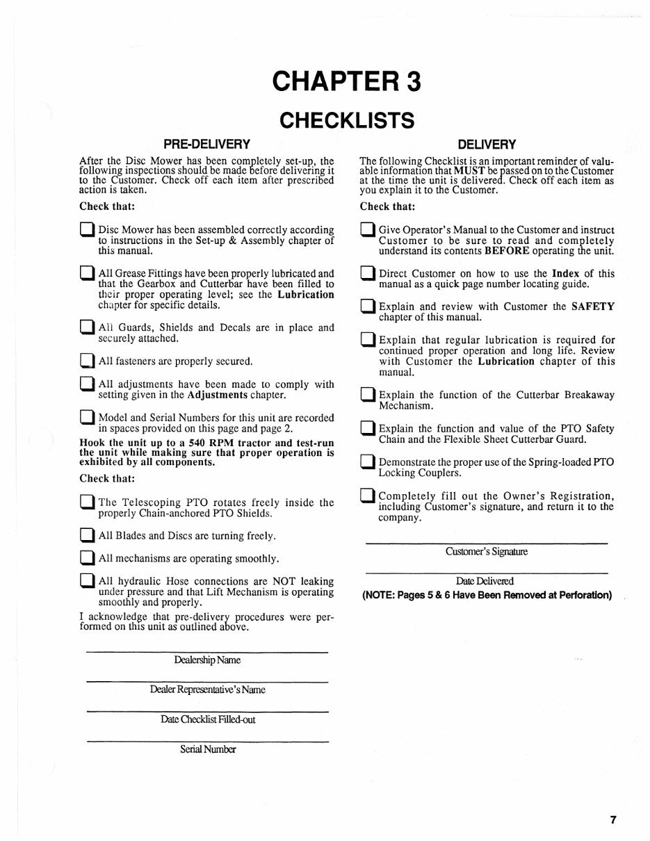
CHAPTER 3 CHECKLISTS PRE-DELIVERY After the Disc Mower has been completely set-up, the following inspections should be made before delivering it to the Customer. Check off each item after prescribed action is taken. Check that: D Disc Mower has been assembled correctly according to instructions in the Set-up & Assembly chapter of this manual. D All Grease Fittings have been properly lubricated and that the Gearbox and Cutterbar have been filled to their proper operating level; see the Lubrication chapter for specific details. D All Guards, Shields and Decals are in place and securely attached. o All fasteners are properly secured. o All adjustments have been made to comply with setting given in the Adjustments chapter. D Model and Serial Numbers for this unit are recorded in spaces provided on this page and page 2. Hook the unit up to a 540 RPM tractor and test-run the unit while making sure that proper operation is exhibited by all components. Check that: D The Telescoping PTO rotates freely inside the properly Chain-anchored PTO Shields. D All Blades and Discs are turning freely. D All mechanisms are operating smoothly. D All hydraulic Hose connections are NOT leaking under pressure and that Lift Mechanism is operating smoothly and properly. I acknowledge that pre-delivery procedures were per- formed on thIS unit as outlined above. Dealership Name Dealer Representative's Name Date Checklist Filled-out Serial Number DELIVERY The following Checklist is an important reminder of valu- able informatlOn that MUST be passed on to the Customer at the time the unit is delivered. Check off each item as you explain it to the Customer. Check that: D Give Operator's Manual to the Customer and instruct Customer to be sure to read and completely understand its contents BEFORE operating the unit. D Direct Customer on how to use the Index of this manual as a quick page number locating guide. D Explain and review with Customer the SAFETY chapter of this manual. D Explain that regular lubrication is required for continued proper operation and long life. Review with Customer the Lubrication chapter of this manual. D Explain the function of the Cutterbar Breakaway Mechanism. D Explain the function and value of the PTO Safety Chain and the Flexible Sheet Cutterbar Guard. D Demonstrate the proper use of the Spring-IoadedPTO Locking Couplers. D Completely fill out the Owner's Registration, including Customer's signature, and return it to the company. Customer's Signature Date Delivered (NOTE: Pages 5 & 6 Have Been Removed at Perforation) 7
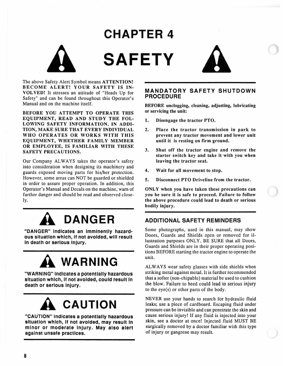
CHAPTER 4 SAFETY A The above Safety Alert Symbol means ATTENTION! BECOME ALERT! YOUR SAFETY IS IN· VOL VED! It stresses an attitude of "Heads Up for Safety" and can be found throughout this Operator's Manual and on the machine itself. BEFORE YOU ATTEMPT TO OPERATE THIS EQUIPMENT, READ AND STUDY THE FOL· LOWING SAFETY INFORMATION. IN ADDI· TION, MAKE SURE THAT EVERY INDIVIDUAL WHO OPERATES OR WORKS WITH THIS EQUIPMENT, WHETHER FAMILY MEMBER OR EMPLOYEE, IS FAMILIAR WITH THESE SAFETY PRECAUTIONS. Our Company AL WAYS takes the operator's safety into consideration when designing its machinery and guards exposed moving parts for his/her protection. However, some areas can NOT be guarded or shielded in order to assure proper operation. In addition, this Operator's Manual and Decals on the machine, warn of further danger and should be read and observed close- ly. A DANGER "DANGER" Indicates an Imminently hazard- ous situation which, If not avoided, will result In death or serious Injury. A WARNING "WARNING" Indicates a potentially hazardous situation which, If not avoided, could result In death or serious Injury. A CAUTION "CAUTION" Indicates a potentially hazardous situation which, If not avoided, may result In minor or moderate Injury. May also alert against unsafe practices. 8 MANDATORY SAFETY SHUTDOWN PROCEDURE BEFORE unclogging, cleaning, adjusting, lubricating or servicing the unit: 1. Disengage the tractor PTO. 2. Place the tractor transmission in park to prevent any tractor movement and lower unit until it is resting on firm ground. 3. Shut off the tractor engine and remove the starter switch key and take it with you when leaving the tractor seat. 4. Wait for all movement to stop. 5. - Disconnect PTO Driveline from the tractor. ONLY when you have taken these precautions can you be sure it is safe to proceed. Failure to follow the above procedure could lead to death or serious" bodily injury. ADDITIONAL SAFETY REMINDERS Some photographs, used in this manual, may show Doors, Guards and Shields open or removed for il- lustration purposes ONLY. BE SURE that all Doors, Guards and Shields are in their proper operating posi- tions BEFORE starting the tractor engine to operate the unit. AL WAYS wear safety glasses with side shields when striking metal against metal. It is further recommended that a softer (non-chipable) material be used to cushion the blow. Failure to heed could lead to serious injury to the eye(s) or other parts of the body.- NEVER use your hands to search for hydraulic fluid leaks; use a piece of cardboard. Escaping fluid under pressure can be invisible and can penetrate the skin and cause serious injury! If any fluid is injected into your skin, see a doctor at once! Injected fluid MUST BE surgically removed by a doctor familiar with this type of injury or gangrene may result.
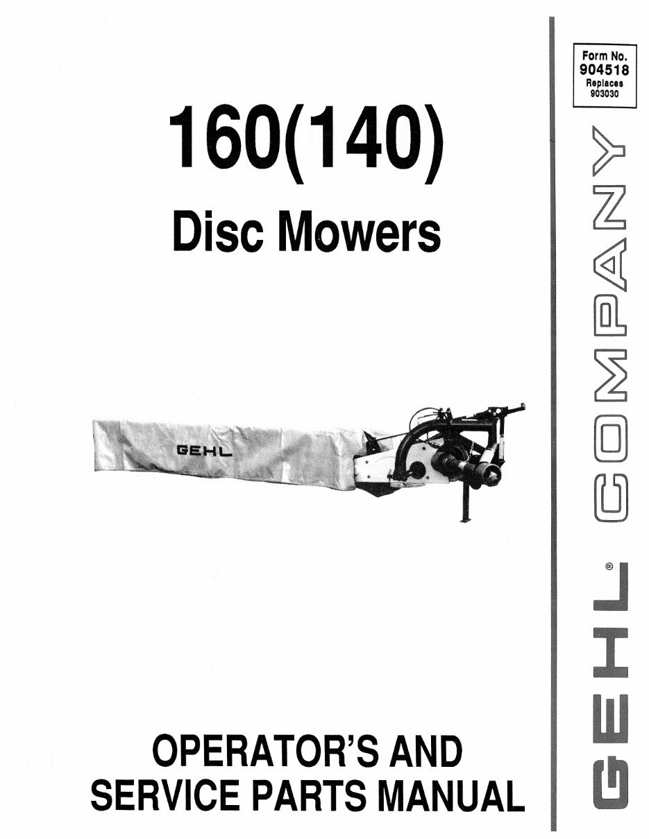
This is the complete parts manual for the GEHL 160 (140) Disc Mowers. It contains all the information needed to properly replace parts on your GEHL 160 (140) Disc Mowers. Filled with illustrations and all part numbers, along with step-by-step instructions and highly detailed exploded pictures and diagrams to show you how to complete the required job correctly and efficiently. It's the same type of manual that your local dealer/mechanic would use.
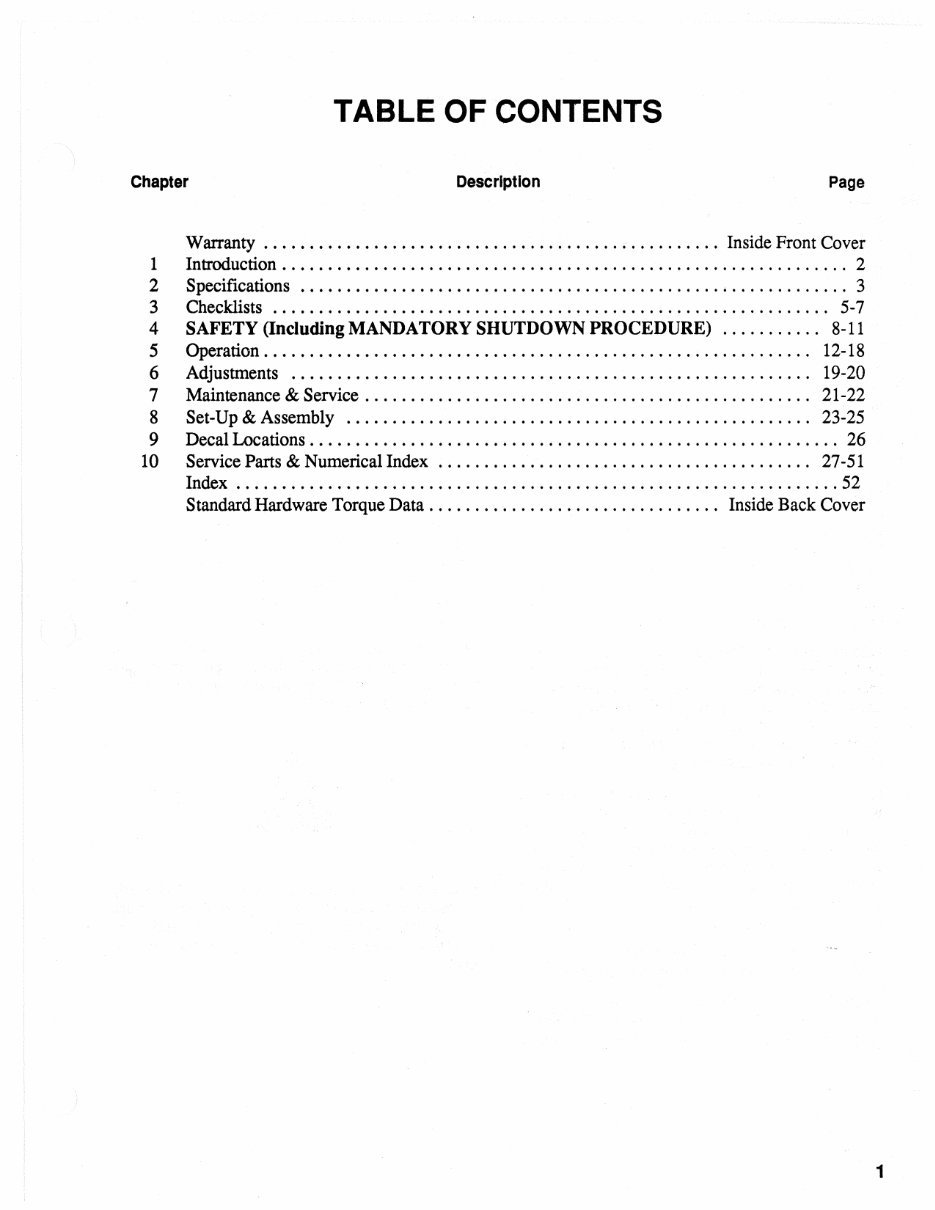
Warranty
Introduction
Specifications
Checklists
SAFETY (Including MANDATORY SHUTDOWN PROCEDURE)
Operation
Adjustments
Maintenance & Service
Set-Up & Assembly
Decal Locations
Service Parts & Numerical Index
Index
Standard Hardware Torque Data
Model Specification: GEHL 160 (140) Disc Mowers
Language: English
File Format: PDF
Requirements: Adobe Reader
Compatible: All Versions of Windows & Mac, APP ISO, iPhone, iPad, Android, etc...
This quality manual is 100% complete and intact, with no missing/corrupt pages/sections.
This file is bookmarked and searchable to make what you need easy to find. Detailed illustrations, exploded diagrams, drawings, and photos guide you through every service repair procedure.
This manual can be viewed on any computer, as well as zoomed and printed. It comes in PDF format, which can work under all PC-based Windows operating systems and Mac as well. It saves to your hard drive and can be burned to CD-ROM.
Instant delivery means there will be no shipping costs or waiting for a paper or CD manual to arrive in the mail. You will receive this manual today via instant download on completion of payment via our secure payment processor.
We accept all major credit/debit cards and PayPal. You can do the repairs yourself and save money.






 Lifetime Access




