QUANTUM 6800 S QUANTUM 5500 S-18 QUANTUM 5500 S-16 QUANTUM 5500 S QUANTUM 4500 S Operator’s manual
Read and follow the sa fety instructions!
EC Declaration of Conformity according to EC Directive 98/37/EEC We CLAAS Saulgau GmbH Zeppelinstrasse 2 D-88348 Bad Saulgau declare under their sole responsibility that the product Forage wagon - model 697 “QUANTUM 5500 S-16 / 5500 S” Forage wagon - model 695 “QUANTUM 4500 S” Forage wagon - model 614 “QUANTUM 6800 S / 5500 S-18 / 5500 S-16 / 5500 S / 4500 S” to which this declaration refers corresponds to the relevant basic safety and health requirements of EC Directive 98/37/EEC, Appendix 1 and to the requirements of the other relevant Directives: - / - For the relevant implementation of the safety and health requirements mentioned in the Directives, the following standard(s) and/or technical specification(s) has (have) been applied: EN 1553 - 1999 Bad Saulgau, January 22th, 2004 Product Development (M. Geng) Supply Chain Management (A. Fetscher) Quality Management (J. Switalski)
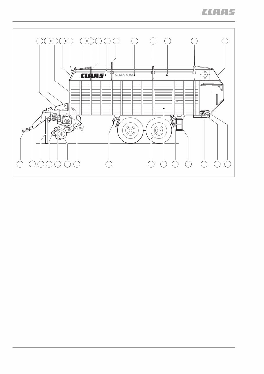
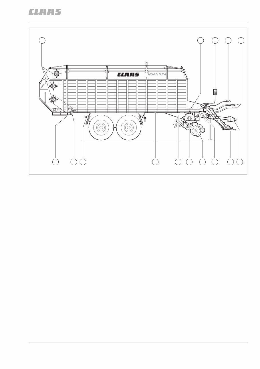
1.1 BA QUANTUM 6800 S / 5500 S-18 / 5500 S-16 / 5500 S / 4500 S - 0299 615.8 Machine overview 1 Machine overview Item No. Description 1 Forage wagon control system 2 Forage wagon central electrical system 3 Automatic loading system “Half Load” 4 Front plate 5 Loading space lighting (6800 S / 5500 S-18) 6 Top plate 7 Hoop 8 Automatic loading system “Full Load” 9 Folding side extension 10 Tailgate 11 Floor conveyor gearbox 12 2-speed motor (optional equipment) 13 Cross conveyor (optional equipment) 14 Ladder (6800 S / 5500 S-18) 15 Wheel chock 16 Inspection hatch 17 Steering axle (optional equipment) 18 Parking brake 19 Knife frame 20 Gauge wheel 21 Rotor gearbox 22 Roll-type crop guard (6800 S / 5500 S-18) Baffle plate (5500 S-16 / 5500 S / 4500 S) 23 Prop stand 24 Articulated drawbar 25 Ring hitch Quantum6800S_01a 12 24 11 17 18 19 20 22 23 25 21 13 16 14 5 3 2 1 7 8 7 9 10 4 6 7 9 7 15 9 Machine overview
2.1 BA QUANTUM 6800 S / 5500 S-18 / 5500 S-16 / 5500 S / 4500 S - 0299 615.8 Introduction 2 Introduction INTRODUCTION This operator's manual provides information on the use, adjustment and operation of the CLAAS self-load- ing forage wagon. Follow the advice on correct maintenance and servic- ing in order to ensure maximum performance and a long service life of your machine. Also, have assembly of your machine and regular inspections carried out by your specialist workshop. Failure to carry out maintenance work, or incorrect operation will result in poor machine efficiency and loss of valuable time. By ensuring correct operation, and carrying out main- tenance and service work with care, you will be able to make full use of the technical knowledge and the expe- rience with which your self-loading forage wagon has been designed. Your CLAAS Service Department Validity This operator's manual is applicable to all self-loading forage wagons: QUANTUM 6800 S / 5500 S-18 / 5500 S-16 / 5500 S / 4500 S Model 614 from serial no. 614 0 2001 to 614 0 2393 Quantum 5500 S-16 / 5500 S Model 697 from serial no. 697 0 1001 QUANTUM 4500 S Model 695 from serial no.: 695 0 1001 Introduction
0299 615.8 - BA QUANTUM 6800 S / 5500 S-18 / 5500 S-16 / 5500 S / 4500 S 3.1 Contents 3 Contents 1. Machine overview ................................................... 1.1 2. Introduction Introduction ............................................................................... 2.1 Validity ................................................................................ 2.1 3. Contents ....................................................................... 3.1 4. Preface Of special importance ............................................................... 4.1 Identification plate ..................................................................... 4.2 Road transport .......................................................................... 4.2 Operating permit ................................................................ 4.3 Operating on public roads .................................................. 4.3 Number plate ...................................................................... 4.3 Regular inspection as required by law ............................... 4.3 5. Safety Rules Designated use ......................................................................... 5.1 Identification of warning and danger signs ................................ 5.1 General Safety and Accident Prevention Instructions ............... 5.2 PTO Operation .......................................................................... 5.3 Brakes ....................................................................................... 5.3 Hydraulic system ....................................................................... 5.4 Wheels and tyres, threaded fastenings ..................................... 5.4 Maintenance ............................................................................. 5.4 Sound pressure level ................................................................ 5.4 Safety decals with pictorials ...................................................... 5.5 6. Specifications QUANTUM 6800 S ................................................................... 6.1 QUANTUM 5500 S-18 .............................................................. 6.1 QUANTUM 5500 S-16 .............................................................. 6.1 QUANTUM 5500 S ................................................................... 6.3 QUANTUM 4500 S ................................................................... 6.3 7. Assembly Assembly .................................................................................. 7.1 QUANTUM 6800 S / 5500 S-18 up to 614 0 02242 ............................................................... 7.1 QUANTUM 5500 S-16 / 5500 S up to 614 0 02242 ............................................................... 7.3 QUANTUM 4500 S up to 614 0 02242 ............................... 7.4 QUANTUM 6800 S / 5500 S-18 from serial no. 614 0 02243 ................................................ 7.5 QUANTUM 5500 S-16 / 5500 S / 4500 S from 614 0 02243 ............................................................... 7.9 Coupling machine for the first time ......................................... 7.13 8. Prior to operation Check and observe the following points prior to operation ....... 8.1 Coupling to the tractor ............................................................... 8.3 Hydraulic articulated drawbar ............................................. 8.3 Ring hitches ........................................................................ 8.4 Height adjustment of the drawbar ....................................... 8.6 Hitching the forced steering system (optional equipment, only available ex-works) ................... 8.7 Adjusting forced steering system ....................................... 8.8 Checking and adjusting the hydraulic pressure ................. 8.8 Drive shaft ........................................................................ 8.10 Adjusting the universal drive shaft ................................... 8.10 Universal drive shaft with CC taper lock seal ................... 8.12 Coupling ........................................................................... 8.12 Uncoupling ....................................................................... 8.12 Electrical system .............................................................. 8.13 Control unit ....................................................................... 8.13 ABS air brake system ....................................................... 8.14 ABS function test .............................................................. 8.14 Adjustment of DIP switches ............................................. 8.14 Hydraulic system .............................................................. 8.16 Open hydraulic system (standard system) ....................... 8.16 Closed hydraulic system .................................................. 8.17 Power-beyond connector ................................................. 8.18 Support foot ...................................................................... 8.18 After attaching the self-loading forage wagon .................. 8.18 Parking the self-loading forage wagon ............................. 8.19 Air brake system .............................................................. 8.19 Two-line system ............................................................... 8.19 Towing with tractors without air brake system ................. 8.20 Hydraulically operated brake system ............................... 8.20 Parking brake ................................................................... 8.21 Setting brake .................................................................... 8.21 Releasing brake ............................................................... 8.21 Wheel chocks ................................................................... 8.21 Inspection hatch ............................................................... 8.22 Unhitching .............................................................................. 8.23 Self-loading forage wagon with air brake system ............. 8.25 Self-loading forage wagon with hydraulically operated brake ................................................................. 8.25 Self-loading forage wagon with ABS air brake system .... 8.25 Prior to transportation ............................................................. 8.26 Hydraulic drawbar damping (optional equipment, only available ex-works) ................. 8.27 Activate drawbar damping ................................................ 8.27 Driving on public roads ..................................................... 8.28 9. Operation Brief introduction ...................................................................... 9.1 Loading operation .............................................................. 9.1 Manual loading operation ................................................... 9.1 Floor conveyor speed ......................................................... 9.1 Knife frame ......................................................................... 9.2 Unloading operation ........................................................... 9.2 Articulated drawbar ............................................................ 9.2 Indicator light (1) ................................................................ 9.2 Loading operation ..................................................................... 9.3 Lowering and lifting the pick-up .......................................... 9.3 Preselecting the working height of the pick-up ................... 9.4 Roll-type crop guard (QUANTUM 6800 S / 5500 S-18) ....................................... 9.4 Baffle plate ......................................................................... 9.5 Contents
3.2 BA QUANTUM 6800 S / 5500 S-18 / 5500 S-16 / 5500 S / 4500 S - 0299 615.8 Contents Adjusting filling mode (filling automatics) ............................ 9.5 End of loading operation ..................................................... 9.7 Switching floor conveyor manually ..................................... 9.7 Setting floor conveyor speed .............................................. 9.7 Opening/closing the knife frame ......................................... 9.8 Unloading operation .................................................................. 9.9 Silage operation .................................................................. 9.9 Unloading the load space ................................................. 9.10 2-speed motor floor conveyor (Optional equipment, only available ex-works) ................. 9.11 Unloading with cross conveyor (Optional equipment, only available ex-works) ................. 9.12 Unloading without cross conveyor .................................... 9.13 Split tailgate (Optional equipment, only available ex-works) ................. 9.13 Opening the lower and top tailgate ................................... 9.13 Opening the lower part of the tailgate ............................... 9.14 Load space lighting ........................................................... 9.15 Operation of self-loading forage wagon .................................. 9.16 Loading operation (general) .............................................. 9.17 After use ........................................................................... 9.17 Standard steering axle (Optional equipment, only available ex-works) ................. 9.18 Locking/unlocking standard steering axle ......................... 9.19 Emergency operation .............................................................. 9.20 Optional equipment ................................................................. 9.22 Tractor electrical system power supply ............................. 9.22 Operating unit extension cable ......................................... 9.22 Load-Sensing Hydraulics control line ............................... 9.23 Drawbar extension for automatic pick-up hitch (M01/0010) ....................................................................... 9.23 Fill indicator for half load ................................................... 9.23 3. Shredder drum (E03/0050) ........................................... 9.24 Hydraulic connection for tractor (R03/0070) ..................... 9.24 Slip yoke kit ....................................................................... 9.24 10. Maintenance Important Maintenance Instructions ........................................ 10.1 Wheels/tyres ..................................................................... 10.1 Brakes and axles .............................................................. 10.1 Air brake system ............................................................... 10.1 Hydraulic system .............................................................. 10.1 Chassis ............................................................................. 10.2 Chains ............................................................................... 10.2 Bolts .................................................................................. 10.2 Lubrication ........................................................................ 10.2 Guards .............................................................................. 10.2 Diagnostic System .................................................................. 10.3 Operation .......................................................................... 10.3 Assignment of inputs ........................................................ 10.4 Assignment of outputs ...................................................... 10.5 Brakes and axles .................................................................... 10.6 Air brake system ............................................................... 10.6 ABS air brake system ....................................................... 10.6 Draining compressed air reservoir .................................... 10.7 Air pipe filter ...................................................................... 10.7 Cleaning the filter element ................................................ 10.7 Components of the air cleaner .......................................... 10.7 Adjusting the brake - checking the brake cylinder piston stroke ........................................................ 10.8 Brake regulator ................................................................. 10.8 Brake linings ..................................................................... 10.8 Forced steering system .......................................................... 10.9 Refilling and bleeding the forced steering system ............ 10.9 Bleeding steering cylinder .............................................. 10.10 Bleeding master cylinder ................................................ 10.10 Adjusting stroke of master cylinder ................................ 10.12 Extending master cylinder .............................................. 10.12 Retracting master cylinder .............................................. 10.13 Setting operating pressure for forced steering system ... 10.13 Cutting mechanism ............................................................... 10.13 Changing the cutting knives ........................................... 10.13 Knife removal ................................................................. 10.14 Knife installation ............................................................. 10.14 Adjusting the scraper unit ..................................................... 10.16 Drive systems ....................................................................... 10.17 Main gearbox .................................................................. 10.17 Floor conveyor gearbox .................................................. 10.17 Floor conveyor drive with 2-speed motor ....................... 10.18 Rotor drive ...................................................................... 10.18 Shredder drum drive (front right) .................................... 10.19 Shredder drum drive (rear right) ..................................... 10.19 Chains .................................................................................. 10.20 Tensioning the drive chains ............................................ 10.20 Tensioning pick-up drive chain ....................................... 10.20 Shredder drum drive chains ........................................... 10.21 Floor conveyor chains .................................................... 10.21 Clutch ................................................................................... 10.22 Adjusting the cut-out clutch for the shredder drum drive ...................................................................... 10.22 Adjusting the pick-up cut-out clutch ................................ 10.23 Cleaning the pick-up cut-out clutch ................................ 10.24 Cam-type cut-out clutch ................................................. 10.24 Air bounce ............................................................................ 10.24 Lifting and lowering device for air-cushioned axles ........ 10.25 Electrical system ................................................................... 10.26 Adjusting the reed switches ............................................ 10.26 Setting upper fill indicator ............................................... 10.26 Setting the rotation sensor ............................................. 10.27 Replacing the PSD (programmable module) .................. 10.27 Replacing the fuse .......................................................... 10.29 Tailgate ................................................................................. 10.29 Adjusting the tailgate ...................................................... 10.29 Adjusting the hydraulic cylinder ...................................... 10.29 Adjusting the support ...................................................... 10.30 Hydraulic system .................................................................. 10.30 Changing pressure filter ................................................. 10.30 Adjusting the speed of the cross conveyor/floor conveyor ................................................. 10.31 Speed - cross conveyor .................................................. 10.31 Accumulator ................................................................... 10.32 Hydraulic hose connections ........................................... 10.33 Gas shock absorber ............................................................. 10.34 Drive shaft ............................................................................ 10.35 Tyres ..................................................................................... 10.36 Maintenance and lubrication holes ....................................... 10.36
0299 615.8 - BA QUANTUM 6800 S / 5500 S-18 / 5500 S-16 / 5500 S / 4500 S 3.3 Contents Guards .................................................................................. 10.37 Fasteners .............................................................................. 10.37 Screw connections ................................................................ 10.37 End of season storage .......................................................... 10.37 Lubrication chart .................................................................. 10.38 11. Lubrication Chart Safety Instructions .................................................................. 11.1 Lubricants ............................................................................... 11.1 Lubrication .............................................................................. 11.1
4.1 BA QUANTUM 6800 S / 5500 S-18 / 5500 S-16 / 5500 S / 4500 S - 0299 615.8 Preface 4 Preface OF SPECIAL IMPORTANCE Note that the CLAAS self-loading forage wagon is also referred to simply as the machine in the following chapters. The instructions set forth in this operator's manual must be read carefully and followed by all persons concerned with the operation, maintenance, repair or inspection of this machine in order to prevent acci- dents. Especially the sections “Safety Rules” and “Prior to Operation” should be read and observed. The use of spare parts, accessories and additional equipment which is not originally manufactured, and checked and released by CLAAS can have its nega- tive effect on specific design features of the CLAAS machine or on its operability, thereby impair active and/or passive operating safety, as well as safety at work (accident prevention). CLAAS will in no way be liable for damage or personal injury caused by the use of other than original CLAAS parts, accessories and additional equipment. Technical specifications, dimensions and weights are understood with the usual tolerances. IMPORTANT: Front, rear, right and left refer to the direction of forward travel. Preface
The Claas Quantum 4500 5500 6800 Self-Loading Forage Wagon Operation Maintenance Service Manual covers the following models:
QUANTUM 6800 S
QUANTUM 5500 S-18
QUANTUM 5500 S-16
QUANTUM 5500 S
QUANTUM 4500 S
It includes detailed information for Model 614 from serial no. 614 0 2001 to 614 0 2393, Model 697 from serial no. 697 0 1001, and Model 695 from serial no. 695 0 1001.
This manual provides step-by-step instructions and highly detailed exploded pictures to assist both professional mechanics and DIY enthusiasts in correct operation, servicing, and maintenance. It is a valuable resource for saving on servicing costs and keeping the vehicle in pristine condition.
Access the same information used by dealers and technicians to service your vehicle. The manual is designed in PDF format for easy viewing on various devices such as Windows PC, Mac, tablet, and smartphone. It is printable for convenience and can be easily discarded after use or kept as a hardcopy.
Instant access eliminates shipping costs and waiting time for delivery. Upon payment completion, you will receive the manual instantly via download. Accepted payment methods include all major credit/debit cards and PayPal.
If you are unable to find a specific manual, you can search the shop or contact customer support for assistance. We strive to provide the most comprehensive manual database online.










 Lifetime Access




