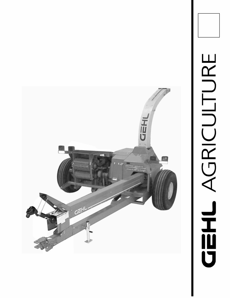
1085/1285 Forage Harvester PARTS MANUAL Form No. 908157 Revision C
Introduction When ordering service parts, specify the correct part number, full description, quantity required, the unit model number and serial number. For your safety and continued proper operation, use only genuine GEHL service parts. The model and serial numbers for this unit are on a plate located on the right side of the main frame, underneath the feed roll housing. “Right’’ and “left’’ are determined from a position standing behind the unit and facing the direction of travel. From this position the bevel gearbox and main drive shaft are on the “left” side. GEHL Company reserves the right to make changes or improvements in the design or construction of any part of the unit without incurring the obligation to install such changes on any previously delivered units. NOTE: On original tire replacement, Company policy prohibits the sale of replacement tires for all GEHL machinery. Replacement wheel sets are available and tire size information is called out with the wheel sets to facilitate replacement tire selection. ALL REPLACEMENT TIRES MUST BE PURCHASED LOCALLY. Refer to the abbreviations table located on this page for the various fastener descriptions. Standard attaching hardware torque values are provided on the inside back cover. In the exploded view parts list, Reference Numbers may have additional information following the Reference Number. A tear drop symbol will indicate an application of a “wet” product, such as oil, and the number inside the tear drop will correspond to the description in the parts list. A number inside a hexagon will be the torque value required, on the associated Reference Number, in foot-pounds. Items shown in the parts list that do not have Reference Numbers are shown for reference purposes only and are NOT available for purchase. Unless otherwise specified, all fasteners are zinc plated; all cap screws and bolts are Grade 5; hexagon nuts for Grade 5 cap screws and bolts are Grade B; hexagon nuts for other cap screws and bolts are Grade A. NOTE: The following abbreviations may be used herein: AR - As Required ASSD - Assembled ASSY - Assembly CB - Carriage Bolt CCW - Counterclockwise CP - Cotter Pin CS - Cap Screw (Hexagon Head) CTR - Center CW - Clockwise DEG - Degree DIA - Diameter FCS - Flanged Cap Screw FHCS - Flat Head Cap Screw FHMS - Flat Head Machine Screw FL - Flanged FLN - Flanged Lock Nut (Hexagon) FLS - Flanged Lock Screw (Hexagon) FW - Flat Washer GA - Gauge GR - Grade HD - Hard or Head HN - Hex Nut HWMS - Hex Washer Machine Screw INCL - Includes JT - Joint LG - Large LN - Lock Nut LT - Left LW - Lock Washer M - Metric MM/mm - Millimeter NF - National Fine NS - Not Serviced PB - Plow Bolt PTO - Power Take Off RHMS - Round Head Machine Screw RPM - Revolutions Per Minute RT - Right SERR - Serrated SHCS - Socket Head Cap Screw SHSS - Socket Head Set Screw SN - Serial Number or Slotted Nut SQ - Square SQHSS - Square Head Set Screw T - Tooth or Teeth TFS - Thread Forming Screw THMS - Truss Head Machine Screw THRD - Thread WLDMT - Weldment # - Number - Torque Required in foot-pounds - Indicates a Fluid Application
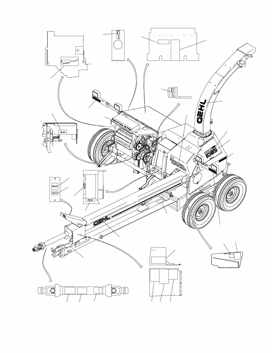
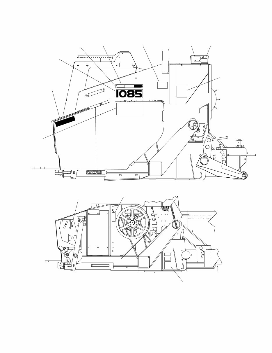
908157/CP0205 2 Printed in U.S.A. DECAL LOCATIONS GENERAL INFORMATION Decal location information is provided to assist in the proper selection and application of new decals, in the event the original decals become damaged or the machine is repainted. Refer to the listing for the illustration reference number, part number, description and quantity of each decal provided in the kit. Refer to the appropriate illustrations for replacement locations. To ensure proper selection of the correct replacement decals, compare all of the various closeup location drawings to your machine before starting to refinish the unit. Then circle each shown decal (applicable to your machine) while checking off its part number in the listing. After you have verified all the decals needed for replacement, place any extra unnecessary decals aside for disposal. NOTE: Refer to the SAFETY Chapter of the Operator’s Manual for the specific information provided on all of the various safety decals furnished in the decal kit(s). NEW DECAL APPLICATION Surfaces MUST be free from dirt, dust, grease and other foreign material before applying the new decal. To apply, remove the smaller portion of the decal backing paper and apply this part of the exposed adhesive backing to the clean surface while maintaining proper position and alignment. Peel the other portion of the backing paper off slowly while applying hand pressure to smooth out the decal surface. CAUTION ALWAYS follow safety precautions on decals. Replace the decals if they are damaged, or if the unit is repainted. If repainting, BE SURE that all applicable decals are affixed to your unit. PAINT NOTICE Use this list to order paint for refinishing: 906315 One Gal. AG Red 902872 One Qt. Light Grey 906316 6 (12 oz. Spray Cans) AG Red 902874 6 (12 oz. Spray Cans) Light Grey The decal kit part number for the 1085 is 155734, and for the 1285 is 155737. The kit includes the following: Ref. Part No. No. Description & Quantity 1 080739 Fuse (Auto-Max Units, Early Models Only) 2 080745 Terminal (Auto-Max Units, Early Models Only) 3 091444 DANGER - Rotating Driveline 4 093020 Lubrication Symbol (9 Places) 5 093202 DANGER - Avoid Electrocution 6 093209 Place Edge 7 093211 Shearbar Removal & Replacement (1085) 074490 Shearbar Removal & Replacement (1285) 8 093366 IMPORTANT - Store Manual Here 9 093367 WARNING - Owner’s Responsibility & Read Manual 10 093373 WARNING - General Safety 11 093374 WARNING - Towing Implement Without Brakes 12 093378 DANGER - Rotating Components (2 Places) 13 093379 WARNING - Wear Goggles When Using Knife Sharpener 14 093381 WARNING - Use Drawbar Transport Lock 15 093653 WARNING - Rotating Driveline 16 094912 Colorbar 12″ (2 Places) 17 094913 GEHL (2 Places) 18 094951 Made in USA 19 122288 GEHL 20 122433 GEHL 21 143007 DANGER - Shield Missing 22 145216 Red Reflector Strip (3 Places) 23 145217 Amber Reflector (4 Places) 24 145218 Orange Marker (3 Places) 25 145234 SMV Marker 26 145316 Length Of Cut Chart 27 145847 Knife Sharpener Instructions 28 153799 1000 RPM 29 154226 CAUTION - Hitchpin alignment 30 154281* Belt Routing (Not Shown ) 31 158060 1085 (2 Places) 154185 1285 (2 Places) 32 158168* Roll Adjustment (Not Shown ) 33 158390 Shearbar Adjustment (1085) 158391 Shearbar Adjustment (1285) 34 158664 Shearbolt Chart (1085) 158665 Shearbolt Chart (1285) 35 158749* Crop Processor (Not Shown ) 36 158778 Lubrication 37 163941 WARNING - To Avoid Injury or Death 38 163957 Decal/Warn Hands Out (3 Places on harvester) (*1 Place on crop processor, not shown ) 39 163962 DANGER - Keep Hands Out 40 173972 Auto-Max/Metal Stop (Auto-Max units) For early models use top portion of 173972 for Auto-Max and bottom portion for Metal Stop 41 Metal Stop (Auto-Max Units, Early Models Only). See note for 173972. * See 1005/1205 Crop Processor manuals for decal locations. NOTE: Order part number 126757 for a 10-ft. roll of replacement striping.
908157/CP0205 4 Printed in U.S.A. NOTE: The decal list has been duplicated for your convenience when selecting decals from the following page. The decal kit part number for the 1085 is 155734, and for the 1285 is 155737. The kit includes the following: Ref. Part No. No. Description & Quantity 1 080739 Fuse (Auto-Max Units, Early Models Only) 2 080745 Terminal (Auto-Max Units, Early Models Only) 3 091444 DANGER - Rotating Driveline 4 093020 Lubrication Symbol (9 Places) 5 093202 DANGER - Avoid Electrocution 6 093209 Place Edge 7 093211 Shearbar Removal & Replacement (1085) 074490 Shearbar Removal & Replacement (1285) 8 093366 IMPORTANT - Store Manual Here 9 093367 WARNING - Owner’s Responsibility & Read Manual 10 093373 WARNING - General Safety 11 093374 WARNING - Towing Implement Without Brakes 12 093378 DANGER - Rotating Components (2 Places) 13 093379 WARNING - Wear Goggles When Using Knife Sharpener 14 093381 WARNING - Use Drawbar Transport Lock 15 093653 WARNING - Rotating Driveline 16 094912 Colorbar 12″ (2 Places) 17 094913 GEHL (2 Places) 18 094951 Made in USA 19 122288 GEHL 20 122433 GEHL 21 143007 DANGER - Shield Missing 22 145216 Red Reflector Strip (3 Places) 23 145217 Amber Reflector (4 Places) 24 145218 Orange Marker (3 Places) 25 145234 SMV Marker 26 145316 Length Of Cut Chart 27 145847 Knife Sharpener Instructions 28 153799 1000 RPM 29 154226 CAUTION - Hitchpin alignment 30 154281* Belt Routing (Not Shown ) 31 158060 1085 (2 Places) 154185 1285 (2 Places) 32 158168* Roll Adjustment (Not Shown ) 33 158390 Shearbar Adjustment (1085) 158391 Shearbar Adjustment (1285) 34 158664 Shearbolt Chart (1085) 158665 Shearbolt Chart (1285) 35 158749* Crop Processor (Not Shown ) 36 158778 Lubrication 37 163941 WARNING - To Avoid Injury or Death 38 163957 Decal/Warn Hands Out (3 Places on harvester) (*1 Place on crop processor, not shown ) 39 163962 DANGER - Keep Hands Out 40 173972 Auto-Max/Metal Stop (Auto-Max units) For early models use top portion of 173972 for Auto-Max and bottom portion for Metal Stop 41 Metal Stop (Auto-Max Units, Early Models Only). See note for 173972. * See 1005/1205 Crop Processor manuals for decal locations. NOTE: Order part number 126757 for a 10-ft. roll of replacement striping.
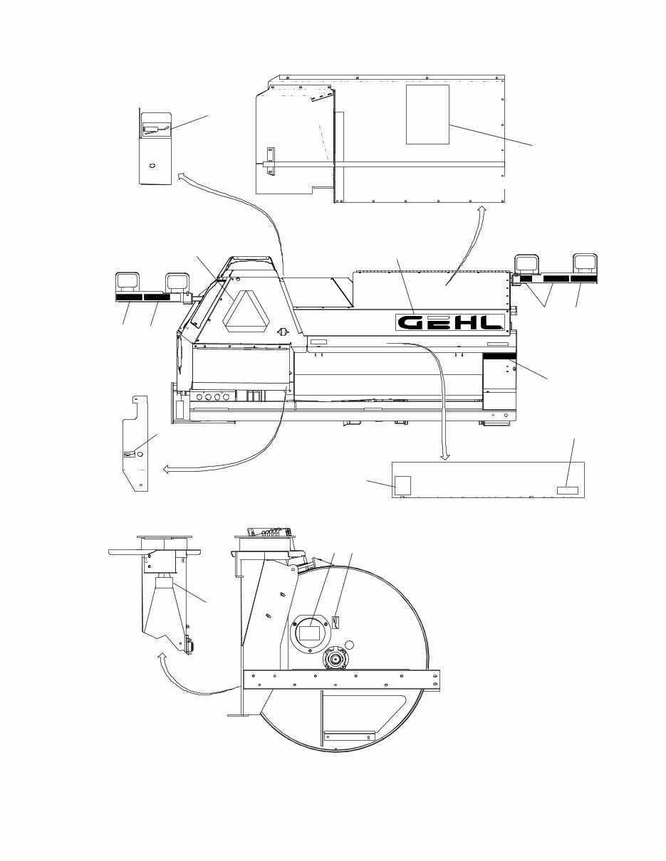
Printed in U.S.A. 5 908157/CP0205 READ READ READ READ Underside of Sharpener Cover Rear View Top of Auger Cover Under Cover Under Cover Rear View of Blower 36 4 22 24 25 20 24 22 22 39 4 4 8 12 38 READ
908157/CP0205 6 Printed in U.S.A. NOTE: The decal list has been duplicated for your convenience when selecting decals from the following page. The decal kit part number for the 1085 is 155734, and for the 1285 is 155737. The kit includes the following: Ref. Part No. No. Description & Quantity 1 080739 Fuse (Auto-Max Units, Early Models Only) 2 080745 Terminal (Auto-Max Units, Early Models Only) 3 091444 DANGER - Rotating Driveline 4 093020 Lubrication Symbol (9 Places) 5 093202 DANGER - Avoid Electrocution 6 093209 Place Edge 7 093211 Shearbar Removal & Replacement (1085) 074490 Shearbar Removal & Replacement (1285) 8 093366 IMPORTANT - Store Manual Here 9 093367 WARNING - Owner’s Responsibility & Read Manual 10 093373 WARNING - General Safety 11 093374 WARNING - Towing Implement Without Brakes 12 093378 DANGER - Rotating Components (2 Places) 13 093379 WARNING - Wear Goggles When Using Knife Sharpener 14 093381 WARNING - Use Drawbar Transport Lock 15 093653 WARNING - Rotating Driveline 16 094912 Colorbar 12″ (2 Places) 17 094913 GEHL (2 Places) 18 094951 Made in USA 19 122288 GEHL 20 122433 GEHL 21 143007 DANGER - Shield Missing 22 145216 Red Reflector Strip (3 Places) 23 145217 Amber Reflector (4 Places) 24 145218 Orange Marker (3 Places) 25 145234 SMV Marker 26 145316 Length Of Cut Chart 27 145847 Knife Sharpener Instructions 28 153799 1000 RPM 29 154226 CAUTION - Hitchpin alignment 30 154281* Belt Routing (Not Shown ) 31 158060 1085 (2 Places) 154185 1285 (2 Places) 32 158168* Roll Adjustment (Not Shown ) 33 158390 Shearbar Adjustment (1085) 158391 Shearbar Adjustment (1285) 34 158664 Shearbolt Chart (1085) 158665 Shearbolt Chart (1285) 35 158749* Crop Processor (Not Shown ) 36 158778 Lubrication 37 163941 WARNING - To Avoid Injury or Death 38 163957 Decal/Warn Hands Out (3 Places on harvester) (*1 Place on crop processor, not shown ) 39 163962 DANGER - Keep Hands Out 40 173972 Auto-Max/Metal Stop (Auto-Max units) For early models use top portion of 173972 for Auto-Max and bottom portion for Metal Stop 41 Metal Stop (Auto-Max Units, Early Models Only). See note for 173972. * See 1005/1205 Crop Processor manuals for decal locations. NOTE: Order part number 126757 for a 10-ft. roll of replacement striping.
Printed in U.S.A. 7 908157/CP0205 READ READ READ READ READ Yellow End Right Side Right Side Cover Removed Read Read 1 2 33 13 16 31 23 27 4 38 18
Gehl 1085 1285 Forage Harvester Parts Manual is a comprehensive electronic guide that provides the same essential information used by dealer technicians and mechanics for diagnosing and repairing vehicles. This professional quality manual is a valuable resource for both professional mechanics and DIY enthusiasts, offering detailed explanations for installation, removal, disassembly, assembly, repair, and check procedures in a sequential order. The manual is 100% complete and intact, with no missing or corrupt pages or sections.
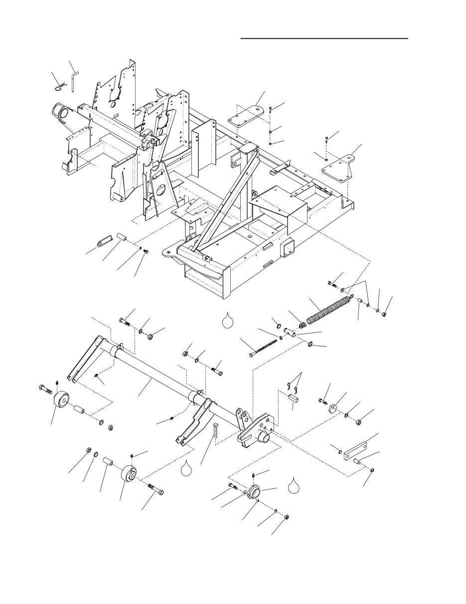
The Parts Manual covers a wide range of topics including Introduction, Table of Contents, Decal Locations, Frame & Attachment Lift, Tongue & Driveline, Cylinder & Cutting Mechanism, Knife Sharpener, Implement Drive, Feed Roll Drive Frame, Feed Roll (Common Parts), Rolls, Drive & Components (Metal Detector), Roll Arm Assemblies, Overrunning Clutch, Spinner & Drive, Blower & Drive, Toolbox, Shields & Covers - Rear, Deflector & Cap, Hydraulics, Control Box Mounting & Wiring, Metal Stop Amplifier Box, Control Box Components, Tunnel & Overload Switch, Lower Front Detector Roll, Shifter Transmission, Bevel Transmission, Spinner Transmission, Hitchjack, Hydraulic Components, Universal Drives, Optional Single Axles & Wheels, Optional Tandem Axles & Wheels, Optional Flotation Axles & Wheels, Accessories, Service Kits - Electrical Connectors, Alphabetical Index, Numerical Index, and Standard Hardware Torque Specifications.
The manual is available in a format compatible with all PC-based Windows operating systems and Mac, and all pages are printable. It is an invaluable and cost-effective resource for maintaining and repairing vehicles, and it is presented in English language. The file format is compatible with Adobe Reader and Win.
Gehl 1085 1285 Forage Harvester Parts Manual is an essential reference for anyone looking to effectively maintain and repair their vehicle.