SECTION 00 -- GENERAL INFORMATION -- CHAPTER 1 00-1 SECTION 00 -- GENERAL INFORMATION Chapter 1 -- General Information CONTENTS Section Description Page Precautionary Statements 2 ....................................................... General Information 3 ............................................................ Before Using the New Machine 3 ............................................... After 8 Hours of Operation 3 ................................................ Tractor Requirements 4 .................................................... Attaching the Mower to the Tractor 5 ............................................ Model H6730 5 ........................................................... Attaching the Mower to the Tractor 9 ............................................ Model H6740 and H6750 9 ................................................. Lowering the Cutter Bar for Field Operation 15 ................................... Transporting the Mower 16 .................................................... Removing the Mower from the Tractor 16 ....................................... Storing the Mower 18 ........................................................ Specifications 19 ................................................................
SECTION 00 -- GENERAL INFORMATION -- CHAPTER 1 00-2 PRECAUTIONARY STATEMENTS PERSONAL SAFETY Throughout this manual and on machine decals, you will find precautionary statements (DANGER, WARNING, and CAUTION) followed by specific instructions. These precautions are intended for the personal safety of you and those working with you. Please take the time to read them. DANGER This word DANGER indicates an immediate hazardous situation that, if not avoided, will result in death or serious injury. The color associated with Danger is RED. M1169 WARNING This word WARNING indicates a potentially hazardous situation that, if not avoided, could result in death or serious injury. The color associated with Warning is ORANGE. M1170 CAUTION This word CAUTION indicates a potentially hazardous situation that, if not avoided, may result in minor or moderate injury. It may also be used to alert against unsafe practices. The color associated with Caution is YELLOW. M1171 FAILURE TO FOLLOW THE DANGER, WARNING, AND CAUTION INSTRUCTIONS MAY RESULT IN DEATH OR SERIOUS BODILY INJURY. MACHINE SAFETY The precautionary statement (IMPORTANT) is followed by specific instructions. This statement is intended for machine safety. IMPORTANT: The word IMPORTANT is used to inform the reader of something he needs to know to prevent minor machine damage if a certain procedure is not followed. INFORMATION NOTE: Instructions used to identify and present supplementary information. ASAE S441.3 FEB04 ISO 11684 VERSION -- FEB 08
SECTION 00 -- GENERAL INFORMATION -- CHAPTER 1 00-3 GENERAL INFORMATION DANGER To prevent injury to bystanders, this mower is not intended for roadside or municipal mowing. This mower is intended for agricultural use only. Failure to comply will result in death or serious injury. M1215 On New Holland equipment, left and right are determined by standing behind the unit, looking in the direction of travel. The serial number plate, 1, for the Models H6730, H6740, and H6750 is located on the left side of the main frame. Record this serial number in the space listed below. Serial Number:_____________________ Give your dealer the model and serial number of your disc mower when ordering parts. Always order genuine New Holland parts from your New Holland dealer. BEFORE USING THE NEW MACHINE 1. Thoroughly read and understand this manual. Pay particular attention to all safety precautions. 2. Check all grease fittings and the gearbox oil levels to insure the machine has been lubricated as recommended in this manual. 3. Check all adjustments to insure they have been made as detailed in the Maintenance section of this manual. After 8 Hours Of Operation 1. Check for loose hardware and tighten any loose bolts. 2. Visually check the entire cutter bar for leakage and correct any leakage before operation. 3. Check mower drive belts for correct tension, and readjust as required. 19986828 1 1
SECTION 00 -- GENERAL INFORMATION -- CHAPTER 1 00-4 Tractor Requirements The Model H6730 disc mower is designed to fit tractors with 540 RPM PTOs with standard ASAE Category I three-point hitches. The tractor must also have adjustable sway bars or a means of locking the lower lift arms from moving sideways. For the H6730 disc mower, the tractor front axle weight should be 782 kg (1725 lbs) or greater prior to attaching the disc mower. This is for tractors with a wheel base range of 78 inch to 84 inch. Add additional weight if required to achieve 782 kg (1725 lbs) or greater. The tractor must also be equipped with one remote hydraulic circuit with a minimum of 104 bar (1500 psi) and a maximum of 193 bar (2800 psi). The tractor should be 45-horsepower minimum for the Model H6730, 55-horsepower minimum for the Model H6740, and 60-horsepower for the Model H6750. Insufficient tractor horsepower may cause stripping and poor cutting. The tractor must have adequate ballasting, wheel spacing, and tire spacing to be stable on hillsides. Too small a tractor may create a stability concern when mowing in hilly conditions. WARNING A tractor with an enclosed cab is recommended when operating a rotary disc cutting machine. Failure to comply could result in death or serious injury. M1183
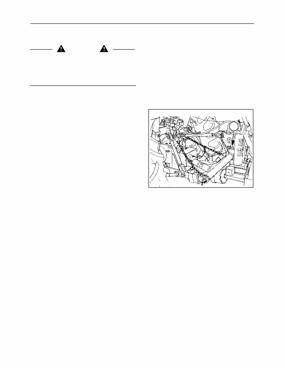
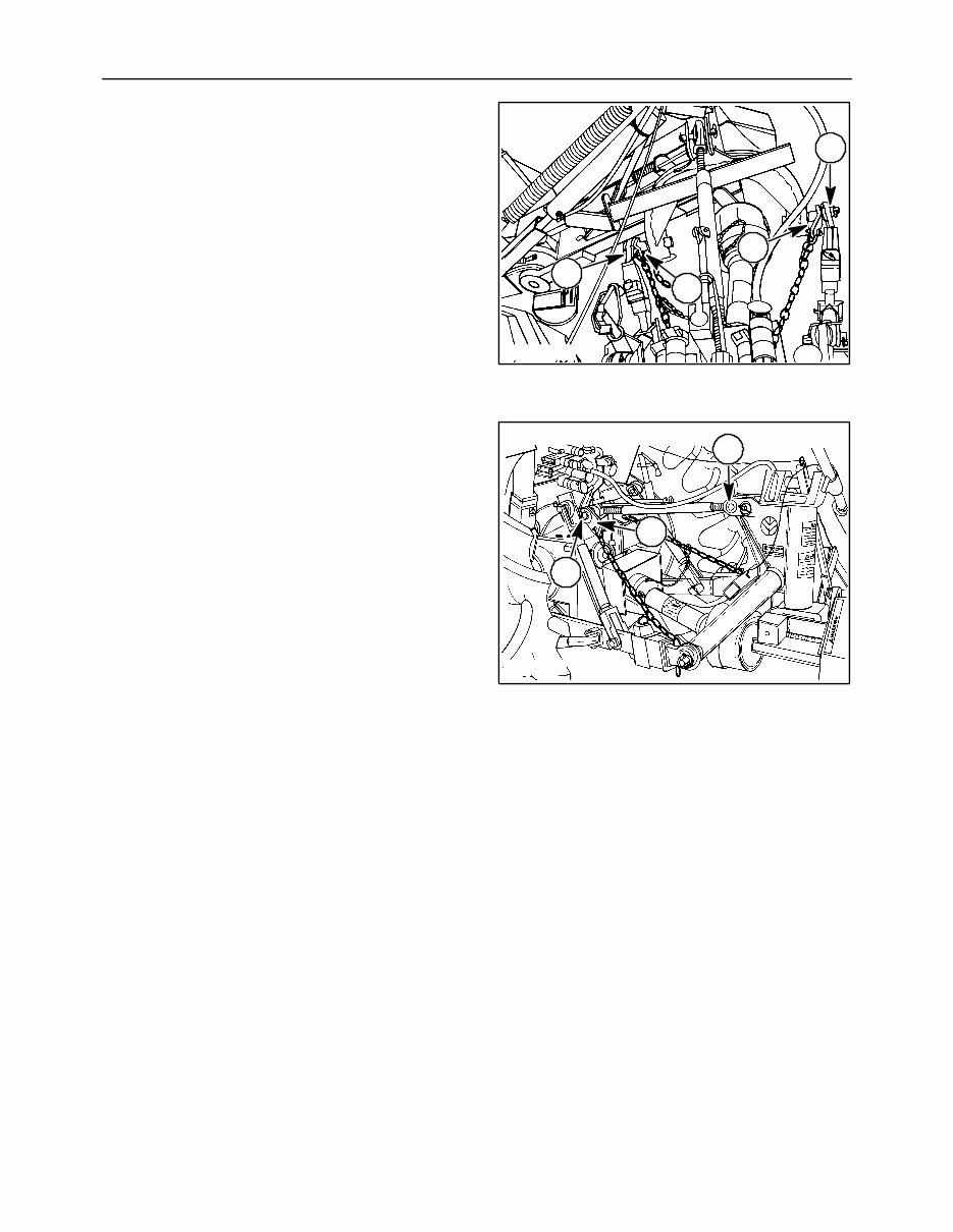
SECTION 00 -- GENERAL INFORMATION -- CHAPTER 1 00-5 ATTACHING THE MOWER TO THE TRACTOR Model H6730 1. Clean all paint or rust from the hitch pins. 2. Attach the plate on the end of the check chains to the outer end of frame hitch pins, 1, as required to clear obstructions on the tractor. Install the check chain plates before attaching the tractor lower links. 3. Back the tractor to the mower and attach the lower links, 2, to the outer end of the frame hitch pins. Secure the links with linchpins. Install the linchpins from the top down. 4. Attach the top link to the tractor, 1, using the pin provided with the tractor top link. 5. Attach the top link to the mower, 2, in the front hole using the pin provided with the mower. NOTE: If necessary, the top link may be mounted in the rear hole on the mower to allow greater top link length range. 6. Attach the check chain plates to the tractor at a top link mounting position, 3, with the pin provided. NOTE: If the check chains interfere with or could damage the tractor PTO shield, relocate the check chain plates to the opposite end of the mower frame hitch pins, or attach to a different location on the trac- tor. NOTE: It may be necessary to position the tractor drawbar to the side or remove it to prevent interfer- ence with the check chains or PTO shaft. 19986827A 2 1 1 2 2 19986828 2 1 3 3
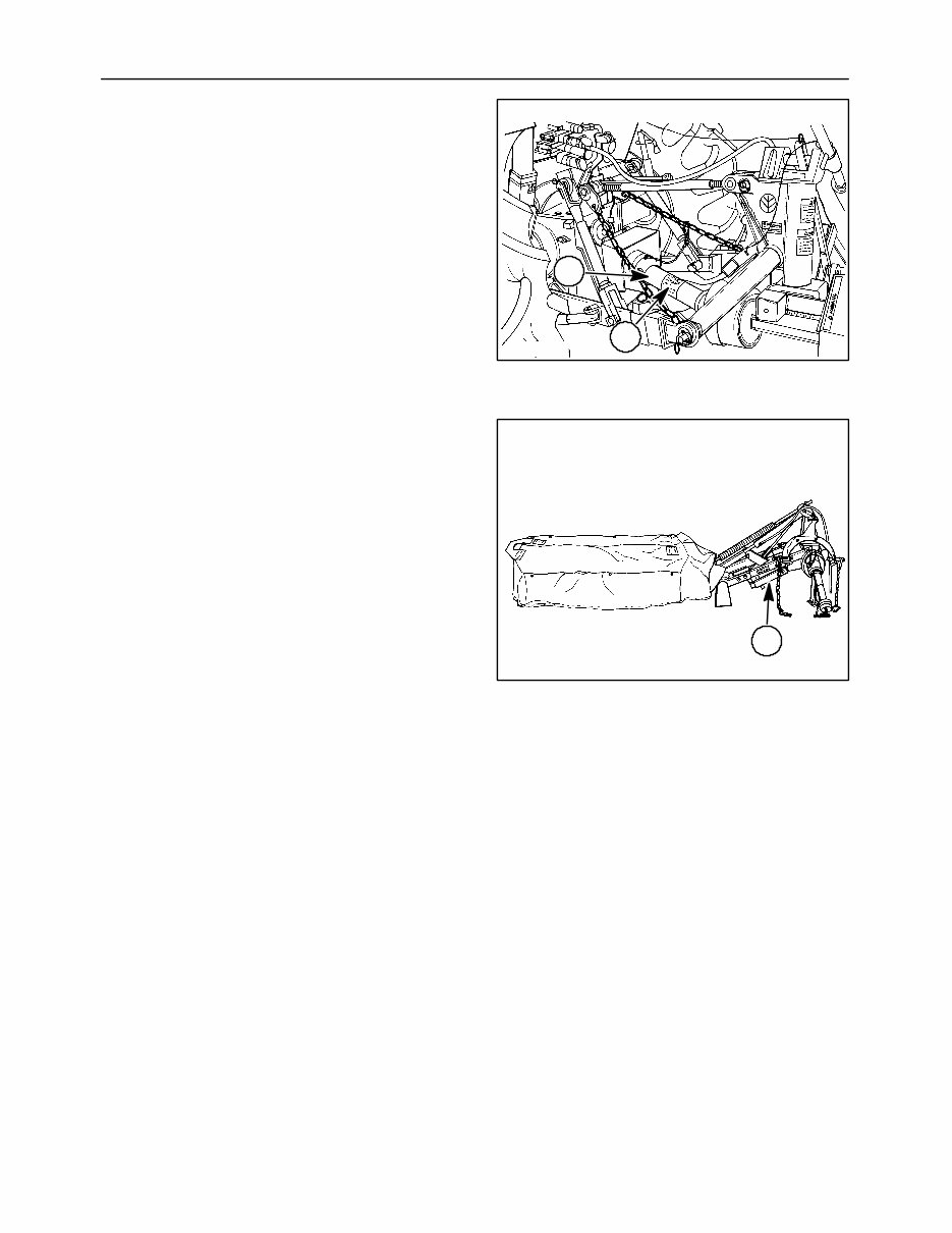
SECTION 00 -- GENERAL INFORMATION -- CHAPTER 1 00-6 7. The PTO assembly must be fitted to the tractor being used. The tubes must overlap at least 102 mm (4 in). At the same time, the tubes, 1 and 2, must be short enough so they do not bottom out. The assembly must also be long enough so it does not pull apart when the breakaway system, 1, operates. NOTE: Most tractors will not require the PTO to be shortened. Separate the front and rear PTO shafts. Connect the front half to the tractor PTO and the rear half to the disc mower input shaft. Raise and lower the machine to find the position where the PTO would be the shortest. Hold the shafts side by side and mark the length to provide 10 mm (3/8 in) clearance between the end of the shafts and the yoke. Measure how much is to be cut from your marks. Cut off an equal length from the front and rear plastic shield. Shorten the PTO telescoping shafts the same amount as the plastic shields. NOTE: Remove the grease sleeve from the rear half of the PTO shaft before shortening the tube. Remove the burrs from the shaft ends with a file or grinder. Clean out the metal chips and filings. Apply grease to the inside of the outer telescoping tube before assembly. Reinstall the grease sleeve on the end of the rear half of the PTO shaft. Check to be sure the shafts do not bottom out, and operate the breakaway to be sure they do not come apart. 19986828 2 1 4 19986837 1 5
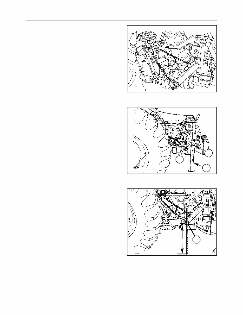
SECTION 00 -- GENERAL INFORMATION -- CHAPTER 1 00-7 8. Attach the PTO assembly to the tractor. 9. Connect the hydraulic hose to the tractor, preferably to a valve section with a float position. Select the appropriate port to allow engaging the float position when lowering. NOTE: Check the tractor operators manual for instructions on which outlet to use for single acting cylinders. 10. Raise the mower with the tractor three-point hitch. Remove pin, 2, and remove the jack stand, 1. Attach the jack stand to the mower frame by sliding the jack stand slots over lugs, 3, on the frame. NOTE: The pin which is attached to the jack stand with a cable will be installed in the flotation system lat- er. 11. Level the tractor lower lift links from side to side. Adjust and lock the sway bars or whatever system the tractor has to remove as much side movement as possible. IMPORTANT: The tractor lower links should be posi- tioned straight behind the tractor, or have minimal off- set. Excessive offset in either direction may cause damage to the mower PTO drive shaft due to exces- sive operating angles or contact with hitch pins, and will also put lead or lag into the cutter bar resulting in reduced cutting width and breakaway perfor- mance. Adjust the limit chain length so the hitch pins, 1, are as close to (but not less than) 609 mm (24 in) as possible from the ground when the mower is supported by the limit chains. NOTE: If the high stubble kit is installed on the mow- er, adjust frame height to 660 mm (26 in) from ground in order to provide adequate flotation. 19986828 6 19986833 2 1 3 7 19986831 1 609 mm (24 in) 8
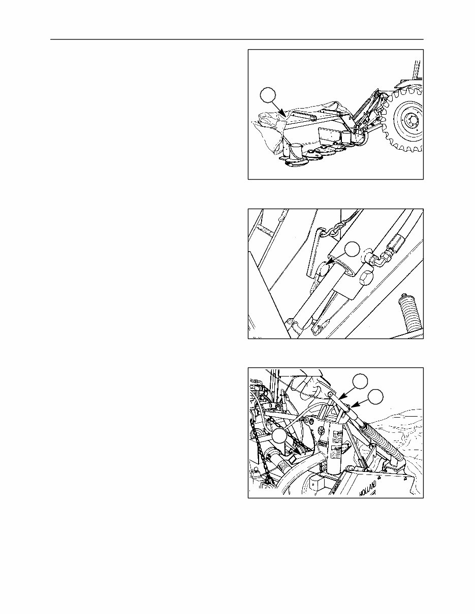
SECTION 00 -- GENERAL INFORMATION -- CHAPTER 1 00-8 12. Fold the front half of the cutter bar curtain, 1, rearward. Secure the curtain with the rubber tie strap, 2. Flip the cutter bar up-stop channel, 3, toward the cutter bar and against the brace. 13. Raise the cutter bar with the tractor hydraulics. Raise it high enough to engage the transport latch, 1. NOTE: Before raising the cutter bar with the hydrau- lic cylinder, make sure there is adequate clearance between the machine and the tractor. The top link may have to be lengthened for the cutter bar to clear the cab. 14. Install the pin, 1, which is attached to the jack stand, 2, in the upper flotation spring rod at 3. The pin has two detent balls and is properly installed when detents are on either side of the flotation spring rod. NOTE: If the pin is inserted too far, the retaining ring may be knocked off and the pin may be lost, causing loss of flotation. 19986836 1 9 A3680-17 1 10 19986832 1 3 2 11
The New Holland H6730, H6740, H6750 Hay Tools Repair Manual is a comprehensive guide designed to assist in maintaining and repairing these powerful machines. Whether you are a professional mechanic or a DIY enthusiast, this manual covers the H6730, H6740, and H6750 models.
Inside, you will find detailed instructions for the removal, installation, disassembly, and assembly of various components. The manual also includes an electrical wiring diagram and hydraulic schematic to aid in troubleshooting any electrical or hydraulic issues.
Additionally, this manual provides diagnostic procedures, specifications, and torque values to ensure proper maintenance and operation of your New Holland hay tools.
Do not let unexpected breakdowns or malfunctions slow you down. With the New Holland H6730, H6740, H6750 Hay Tools Repair Manual, you will have the knowledge and confidence to keep your equipment running smoothly.