188 662.1 - RHB LEXION 460 – 405 1.1.1 General GENERAL Introduction This CLAAS REPAIR MANUAL is to assist in preserving the permanent working order and therefore the high value of your CLAAS combine-harvester by careful maintenance and service. Experience gathered by both our service engineers and factory staff has been compiled in this REPAIR MANUAL. The figures explain the procedure of repairs and the text describes the different adjustments to be made, the use of CLAAS special tools etc. The illustrations included in support to the explana- tions show the sequence of major repairs so that minor repairs can easily be followed. The CLAAS REPAIR MANUAL is filled in a folder which allows to insert supplementary pages as issued following technical developments and to always have an updated manual at hand for reference. To be sure, always compare settings and filling capacities with specifications stated in the current Operator’s Manual which applies to the combine- harvester. CLAAS KGaA mbH Service Department General
1.1.2 RHB LEXION 460 – 405 - 188 662.1 General Introduction to the CLAAS Repair Manual The CLAAS REPAIR MANUAL is divided into main groups and subgroups. The first figure at the bottom of each page refers to the main group whereas the second figure following the point indicates the subgroup; the figure behind the second point indicates the page number. In each subgroup, the figures and pages are numbered consecutively, starting at 1. Where differences between the machine types must be observed, this is indicated in headings. Where a service procedure applies to all machines covered by this book, the machine names are not specifically given. When supplements are to be added, the subgroups are supplemented or exchanged. Any possible supplements are filed in the respective main group / subgroup and the table of contents is updated and replaced. The symbols communicate brief messages when recurring service procedures are described. Their meaning is explained at the beginning of this manual. The section “GENERAL REPAIR INSTRUCTIONS” at the beginning of this manual contains useful practical hints. Read and follow these fundamental instructions. They are the basis for reliable service and durability of parts after repairs have been carried out. The description of a particular service procedure can easily be found by checking the table of contents of the appropriate main group / subgroup.
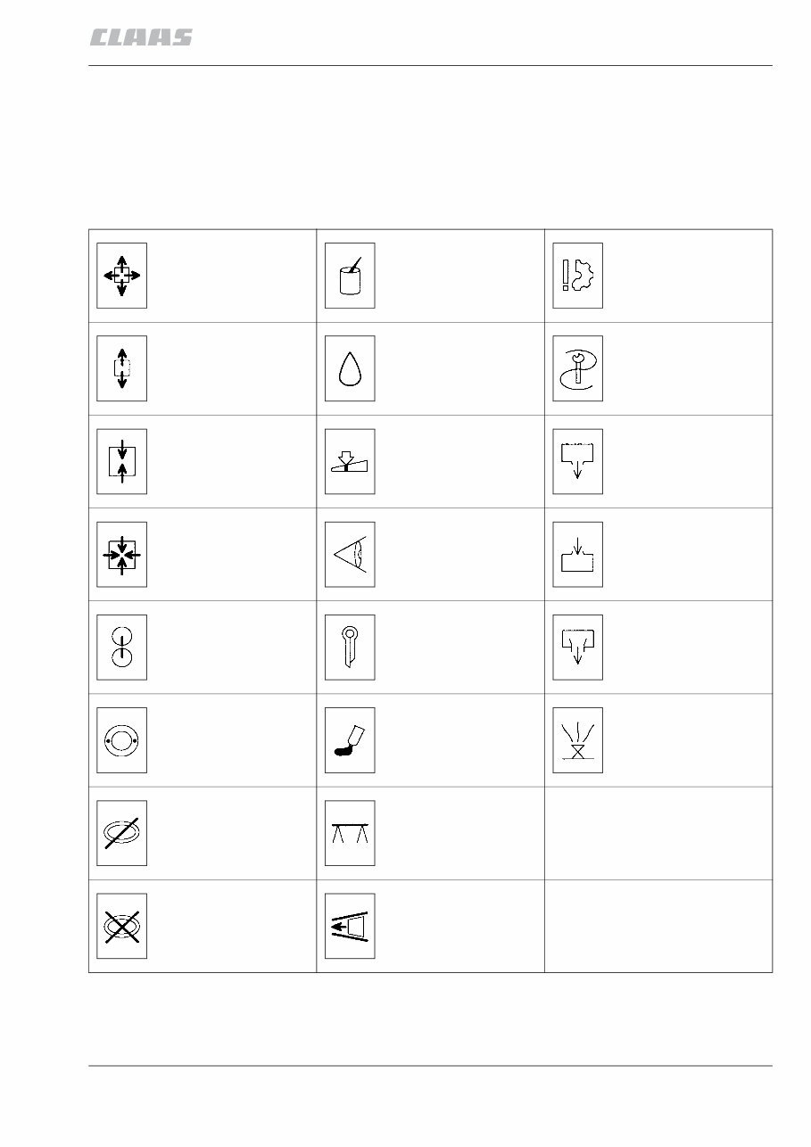
188 662.1 - RHB LEXION 460 – 405 1.1.3 General Key to symbols This CLAAS REPAIR MANUAL uses some symbols as defined in the “DIN 30600 Symbol summary” by the German Standardisation Institute. The meaning of these symbols will be easily recog- nised and remembered by the user. These symbols are to help to quickly recognise recurring service procedures and they also help to communicate information shown on the illustrations. Dismantle, remove Grease Prevent damage to materials Disassemble Oil Use special tool Assemble Adjust / set Drain, outlet Install, mount on Check visually Fill, filler opening Mark Unlock, release, secure Overflow Balance Lock by means of liquids, glue, seal Bleed Possibly reusable Underprop, support Renew on each assembly Observe direction of installation General
1.1.4 RHB LEXION 460 – 405 - 188 662.1 General
188 662.1 - RHB LEXION 460 – 405 1.5.1 Specifications SPECIFICATIONS Lubricants chart Component Type of lubricant Viscosity Capacity Hydraulic system Multi-grade hydraulic oil ISO-VG 46 conforming to DIN 51 524 specifications, part 3** approx. 20 litres (oil change) approx. 70 litres (new system filling) Manual gearbox 20 t / 17 t / 15 t Multi-grade transmission oil conforming to (MIL-L-2105 B) API-GL-5-90 specifications 90 7.0 litres Manual gearbox 20 t HD 6.5 litres Final drives 20 t / 17 t 8.0 litres each Final drives 15 t / single-step 5.0 litres each Planetary gearbox 20 t 7.5 litres each Threshing drum reduction gearbox Multi-grade transmission oil conforming to (MIL-L-2105) API-GL-4-90 specifications 90 1.8 litres Transfer gearbox (engine output shaft) 3.0 litres Grain tank unloading tube Upper angle drive Rolling bearing grease, e.g. Alvania R3 270 g Grain tank unloading tube Lower angle drive (up to serial no. …) 530 g Grain tank unloading tube Lower angle drive (from serial no. …) 900 g Foot brake ATE brake fluid SAE-specifications DOT 4 Reservoir must always be full SANDEN compressor SD 7 H 15 Sanden oil SP 20 PAG as required (approx. 300 cm³ for initial filling) Refrigerant R 134a 1800 g ** When selecting the hydraulic oil, the following conditions need to be met: Pour point < -25 °C (DIN ISO 3016) Viscosity 0 °C < 600 cSt. (DIN 51 562) Viscosity 40 °C max. 50.6 cSt. (DIN 51 562) Viscosity index > 170 (DIN ISO 2909) The oil must have detergent properties! Specifications
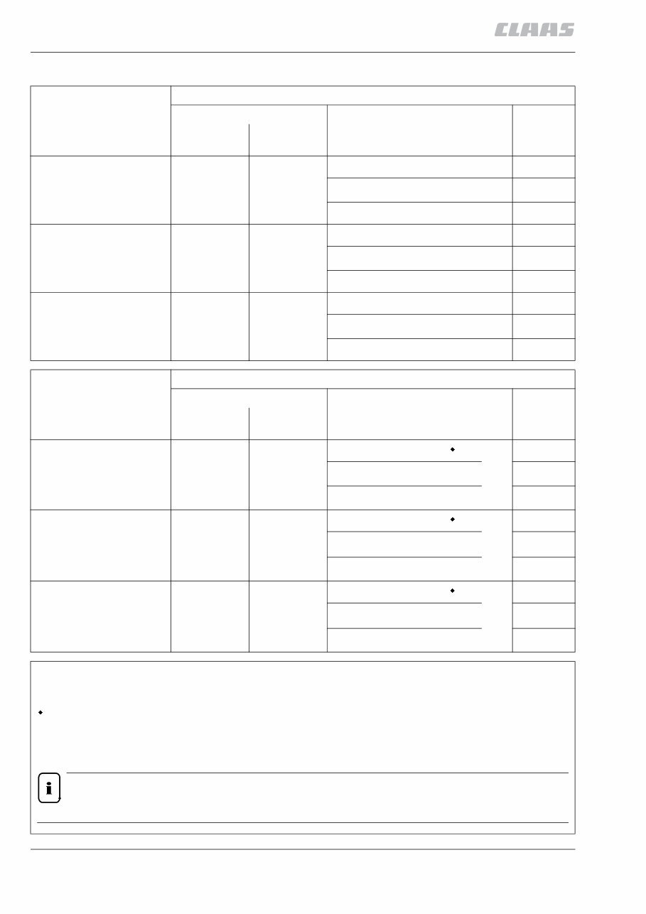
1.5.2 RHB LEXION 460 – 405 - 188 662.1 Specifications Hydraulic pressure values Machine type Working hydraulics Quantity / Litres Set pressure bar Refill Oil change at corresponding pressure relief valve LEXION 460 / 450 / 440 approx. 70 approx. 20 Lifting hydraulics 175 +15 Steering * 150 +15 Low pressure 19 +2 LEXION 430 / 420 / 415 approx. 70 approx. 20 Lifting hydraulics 175 +15 Steering * 150 +15 Low pressure 19 +2 LEXION 410 / 405 approx. 70 approx. 20 Lifting hydraulics 175 +15 Steering * 150 +15 Low pressure 19 +2 Machine type Hydrostatic ground drive Quantity / Litres Set pressure bar Refill Oil change at corresponding pressure relief valve LEXION 460 / 450 / 440 approx. 70 approx. 20 Operating pressure S4 420 +30 Filling pressure ** Purge pressure 23 LEXION 430 / 420 / 415 approx. 70 approx. 20 Operating pressure S5 420 +30 Filling pressure ** Purge pressure 23 LEXION 410 / 405 approx. 70 approx. 20 Operating pressure S5 420 +30 Filling pressure ** Purge pressure 23 * = When making new settings, note the circulation pressure and add the value to the one given. ** = Filling pressure 4 – 6 bar above purge pressure = Max. absolute pressure Hydrostatic ground drives: S4 = SAUER 90 R 130 / 90 M 100 S5 = SAUER 90 R 100 / 90 M 100 When selecting the hydraulic oil, the following conditions need to be met: Pour point < -25 °C (DIN ISO 3016) Viscosity 0 °C < 600 cSt. (DIN 51 562) Viscosity 40 °C max. 50.6 cSt. (DIN 51 562) Viscosity index > 170 (DIN ISO 2909) The oil must have detergent properties! NOTE! The working and the ground drive hydraulics have one common hydraulic oil tank. +2 –1 +2 –1 +2 –1
188 662.1 - RHB LEXION 460 – 405 1.3.1 General repair information GENERAL REPAIR INFORMATION Reason of damage Identify reason of damage, limit the case of damage and safeguard the machine. Spare parts Use genuine CLAAS spare parts and corresponding CLAAS special tools. Indicate the machine number of the CLAAS combine and when the engine, front attachments, maize header, cutterbar and maize picker are concerned, also the respective serial numbers when ordering spare parts and in case of technical questions. This is necessary as otherwise, incorrect spare part deliveries may result. Engine Always disconnect the battery cable (–) prior to starting work on the engine. Gearboxes When removing the gearboxes, first drain the oil and then remove the gearbox. Separate parts which are firmly connected with each other by means of a soft metal-tip or plastic-tip hammer. Alternator ATTENTION! – Never disconnect the cables connecting the con- troller, alternator and battery whilst the alternator is running. – Ensure correct polarity when connecting the cables to the battery as otherwise the diodes will be burnt out. – Do not carry out any work on live parts unless the engine is stopped and the battery cables are disconnected. – The normal practice of striking a cable against earth to check for current is not permitted with alternators. This will damage the semiconductors. – Before doing any electric welding on the combine, be sure to disconnect the cables from the alter- nator terminals! – The battery provides the current for the field excitation required to start the alternator via the battery charge indicator bulb. Blown bulbs must therefore be replaced to ensure reliable field excitation. Tensioning the steel roller chains Find the centre point in the slack span between sprockets. With the tight span slightly under load, push in the centre point of the slack span with the thumb. The chain tension is correct when its slack span deflects about 2% of the centre distance between shafts. Check chain tension more frequently when using new chains. Example: For a distance between centres of shafts of 500 mm, the slack span of the chain should deflect about 10 mm. Taper ring fasteners Taper ring fasteners provide a safe mechanical con- nection, even when transmitting high forces from the driving element on the shaft and vice versa, if they are properly prestressed. Installation: When installing taper ring fasteners, it is important that the shaft, hub, parallel key and the taper rings have been thoroughly cleaned, that semi-fluid lubricant of NLGI class 00 (e.g. CLAAS semi-fluid lubricant EP 00) is applied and that the components are tightened to the specified torque in the correct order of assembly. ATTENTION! No solid grease must be used when assembling the parts. Removal: After loosening the axial clamping, loosen the taper ring fasteners with a sharp blow, using a block-ended tube. ATTENTION! The inside diameter of the block-ended tube must be large enough to extend over the tapered ring. Self-locking bolts (with microencapsulated adhesive) Replace self-locking bolts, e.g. Verbus-Plus / Imbus-Plus and similar types every time such bolts are removed. In exceptional cases, they may be reused up to three times. Always observe the specified tightening torque. General repair information
1.3.2 RHB LEXION 460 – 405 - 188 662.1 General repair information Always tighten self-locking bolts with microencap- sulated adhesive rapidly to the specified tightening torque. When removing these bolts, quickly unscrew them completely. These self-locking bolts must not come into contact with sealing compound (e.g. “Epple 33” or similar products). In individual cases, bolts with liquid locking compound can be used instead of self-locking bolts only where these bolts can be heated up to approx. 200 °C for removing them. Ensure that the specified quality grade of bolts (8.8/10.9 or similar grades) is observed here as well. Self-locking bolts with microencapsulated adhesive may be used only where operating temperatures will not exceed +90 °C max. These bolts can be subjected to full stress after 24 hours at +20 °C. To speed up the curing time, heating may be applied (e.g. to 15 minutes at +70 °C). Liquid locking compound (e.g. Delo-ML 187 / Loctite 242 or similar types) Use liquid locking compound only where specified by the manufacturer. Correct application: Metal surfaces where liquid locking compound is to be applied must be absolutely free from grease. Use the “Activator” included in the workshop package for cleaning. Before applying the liquid locking compound, the metal surfaces where Activator has been applied must have dried. Especially in blind holes, no Activator (cleaning agent) residues are allowed. When installing bolts, apply the liquid locking compound only to the internal thread (nut) if possible in small quantities (drops). In blind holes only wet approx. 1d (d = nominal diameter of bolt) at the thread bottom. The same applies to any extra-long female threads. When applying the liquid locking compound to the bolt or at the top end of a female thread, the liquid locking compound will spread over the entire thread length when screwing the bolt in. As a result, too much break-away torque is required to remove the bolt – Danger of breaking! Threaded assemblies secured with liquid locking compound can be easily unscrewed by heating them up to approx. 200 °C. Correct installation of lock collar bearings Lock collar bearings are tightened on the shaft by rotating the eccentric ring over the inside bearing ring. Prior to installation, apply semi-fluid lubricant of NLGI class 00 (e.g. CLAAS semi-fluid lubricant EP 00) to the inside ring and the shaft to make bearing removal easier during future repairs. Always fasten the eccentric ring moderately in the direction of rotation of the shaft and lock by means of a set screw. To remove the bearing, loosen the eccentric ring in opposite direction of rotation of the shaft. Correct installation of adapter sleeve bearings Adapter sleeve bearings do not require a specially machined bearing seat. They may be mounted on any drawn or scalped shaft. This is an advantage because it allows the shaft to be axially moved as required to obtain correct alignment. Always install adapter sleeve bearings according to the conical inside ring. Clean the taper lock adapter sleeve and the shaft and check that the sleeve nut runs easily so the taper lock adapter sleeve will not turn on the shaft when tightening. Tightening the bearing: First tighten the sleeve nut to the point where the taper lock adapter sleeve has no more play and is under slight preload. Now tighten the nut by approx. 90° and continue turning until the next nearest slot fits the tab. Secure sleeve nut with the tab. Loosening the bearing: Bend up the tab which secures the sleeve nut and first back off the nut a few turns only (the thread must still fully grip). Loosen the taper lock adapter sleeve with a sharp blow, using a block-ended tube. Ferrule fittings on hydraulic lines When pre-assembling the unit and for pre-assembled factory-delivered ferrule fittings, the following applies: installation is in the associated, well-oiled threaded joint with half a turn of the union nut beyond the point where resistance is felt. Pre-assembly: 1. Cut off the tube at right angles. Do not use a pipe cutter! This will slant the tube wall, causing heavy inside and outside burrs. Slightly deburr the tube end on the inside and outside (do not chamfer!) and clean it. In case of tube bends, the straight tube end up to where the bending radius starts must be at least twice the height of the union nut. 2. Push the union nut and the ferrule on the tube.
188 662.1 - RHB LEXION 460 – 405 1.3.3 General repair information 3. Push the tube against the stop in the union and tighten union nut until the ferrule grips the tube (the tube must not rotate with the nut). This point can be felt because increase power is needed from here. 4. Tighten the union nut half a turn beyond the point where resistance is felt. 5. Check the cut made by the ferrule edge: A visible shoulder must fill the space before the ferrule front end. The ferrule may rotate, but axial displace- ment must not be possible. Installation: Insert the pre-assembled tube into the well-oiled threaded joint, tighten the union nut up to the point where resistance is felt and then half a turn beyond this point. Re-installation: Every time the ferrule fitting has been loosened, retighten the union nut without using increased force. Ferrule fitting leaks: If a ferrule fitting leaks, first loosen the union nut until some oil escapes and then tighten it as specified. Progressive ring fittings on hydraulic lines When pre-assembling the unit and for pre-assembled factory-delivered progressive ring fittings, the following applies: installation is in the associated, well-oiled threaded joint with half a turn of the union nut beyond the point where resistance is clearly felt. Pre-assembly: 1. Cut off the tube at right angles. Do not use a pipe cutter! This will slant the tube wall, causing heavy inside and outside burrs. Slightly deburr the tube end on the inside and outside (do not chamfer!) and clean it. In case of tube bends, the straight tube end up to where the bending radius starts must be at least twice the height of the union nut. 2. Push the union nut and the progressive ring on the tube. 3. Push the tube against the stop in the union and tighten union nut until the progressive ring grips the tube (the tube must not rotate with the nut). This point can be felt because increase power is needed from here. 4. Tighten the union nut half a turn beyond the point where resistance is felt. 5. Check the cut made by the progressive ring edge: A visible shoulder must fill the space before the progressive ring front end. The progressive ring may rotate, but axial displacement must not be possible. Installation: Insert the pre-assembled tube into the well-oiled threaded joint, tighten the union nut up to the point where resistance is felt and then half a turn beyond this point. Important: Back up the threaded joint with a wrench! Re-installation: Every time the progressive ring fitting has been loosened, retighten the union nut until resistance is felt and then continue for half a turn beyond that point. Important: Back up the threaded joint with a wrench! Progressive ring fitting leaks: If a progressive ring fitting leaks, first loosen the union nut until some oil escapes and then tighten it as specified. ATTENTION! Failure to observe the tightening torques reduces the nominal power and the service life of the fitting, resulting in leaks and in the tube slipping out. Taper fittings on hydraulic lines Installation: Apply oil to the O-ring on the taper. Tighten the union nut a third of a turn beyond the point where resistance is felt. Important: Back up the threaded joint with a wrench! ATTENTION! Failure to observe the tightening torques reduces the nominal power and the service life of the fitting, resulting in leaks and in the tube slipping out. Welding ATTENTION! When carrying out electric welding work on the machine, observe the following points: 1. Turn off the battery isolating switch! 2. Disconnect the connector to the display monitor.
1.3.4 RHB LEXION 460 – 405 - 188 662.1 General repair information 3. Pull out the electrical plug-in modules in the central terminal compartment. 4. Disconnect the electrical connectors between the engine and the main wiring loom. 5. Always connect the earth clamp of the welder in the near vicinity of the area where the welding is being carried out. Some advice for speedy and correct repair work: – Mark machine parts prior to disassembly to ensure their correct left-to-right positions and balance when reassembled. – Fit expansion pins with the slot facing the side under load. When fitted with a quarter turn from this position, they will get loose, fall out or shear off. – Replace split pins, locking wires, locking plates, tab washers and lock washers when carrying out repairs. – Fit lubricated ball and slide bearings with high-quality grease. – Align sprockets and V-belt pulleys toward each other. – Care for strict cleanliness when working on hydraulic systems. – Never mix different oil types. – Run the machine or operate machine assemblies at low speed after any repair.
You're Reading a Preview
What's Included?
Lifetime Access
Fast Download Speeds
Online & Offline Access
Access PDF Contents & Bookmarks
Full Search Facility
Print one or all pages of your manual
$41.99
Claas Lexion 400 Series (405, 410, 415, 420, 430, 440, 450, 460) Combine Harvesters OEM Service & Repair Manual
Claas Lexion 400 Series Combine Harvesters OEM Service & Repair Manual
Models covered:
Claas 405
Claas 410
Claas 415
Claas 420
Claas 430
Claas 440
Claas 450
Claas 460
The Claas Lexion 400 Series Combine Harvesters OEM Service & Repair Manual lays out everything you need to keep these harvesters running strong when the season gets busy. It’s built for pros who need dependable technical detail—but written clear enough for DIYers with a wrench and some patience.
From engine cooling and separator components to final drives and chopper systems, the manual dives deep into each mechanical system. You’ll find breakdowns of hydraulic pump servicing, gearbox repairs, cutterbar assembly, and chaff spreader adjustment. Even the more specialized components—like the 3-D sieve pan and rotary screen—get full diagnostic coverage.
Content overview:
General information, specifications, and safety guidelines
Full breakdown of the 3-D sieve pan control system and separator components
Sectional views, drive diagrams, and component layouts
Accelerator, air conditioning, and brake system diagnostics
Chopper drive, chaff spreader, and cleaning fan system details
Engine, cooling system, and electric system troubleshooting
Cutterbar, drive axle, drive belts, and final drives procedures
Fuel system, fan drive, and feed rake conveyor service
Hydraulic circuit diagrams, cylinders, and pump service procedures
Gearbox, oil cooler, parking brake, and impeller system repair
Straw chopper, straw walker, spreader, and threshing systems
Steering system, axles, and under-walker return floor diagrams
Rotary screen and sieve pan mechanical drive systems
Tightening torques, valve combinations, and maintenance schedules
Whether you’re mid-harvest or doing off-season maintenance, this manual is your go-to reference. It's full of practical repair procedures, torque specs, and exploded views to keep your Claas machines field-ready year after year.
Printable: Yes Language: English Compatibility: Pretty much any electronic device, incl. PC & Mac computers, Android and Apple smartphones & tablet, etc. Requirements: Adobe Reader (free)
Reviews
Q&A
Recently Viewed
5,521,897Happy Clients
2,594,462eManuals
1,120,453Trusted Sellers
15Years in Business
Price:
Actual Price:
Claas Lexion 400 Series (405, 410, 415, 420, 430, 440, 450, 460) Combine Harvesters OEM Service & Repair Manual










 Lifetime Access




