5HSODFHV %DOH &RPPDQG 3OXVZ )RU %5$ %5$ %5$ %5$ 5RXQG %DOHUV NOT FOR REPRODUCTION
0-1 CONTENTS GENERAL INFORMATION 1-1 ............................................. INSTALLATION OF TRACTOR-MOUNTED COMPONENTS 2-1 ................ OPERATORS PANEL OPERATION 3-1 ..................................... FIELD OPERATION 4-1 ................................................... MAINTENANCE 5-1 ....................................................... TROUBLESHOOTING 6-1 ................................................. INDEX 6-21 .............................................................. NOT FOR REPRODUCTION
0-2 NOT FOR REPRODUCTION
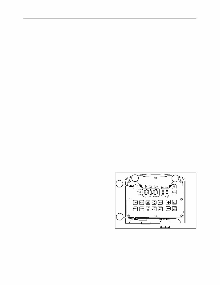
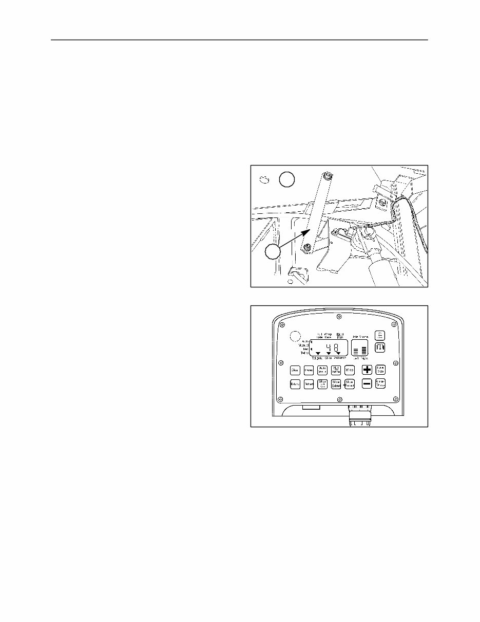
1-1 SECTION 1 GENERAL INFORMATION This manual covers the electronic/electrical portion of the Bale Command Plus system. Refer to the baler operators manual for the mechanical portion of the Bale Command Plus system. Bale Command Plus is a computerized control system that allows the operator to visually and audibly know when to shift the baler from one side of the windrow to the other for proper feeding of the round baler. The controller also provides the operator with the ability to select the desired number of twine or net wraps on the bale and wraps the bale automatically. The system retains the selected wrap program as long as desired but can be easily reprogrammed. The Bale Command Plus system also controls operation of the Bale Slicet system knives and activates rotor reverse on balers equipped with those options. NOTE: The Bale Command Plus system is designed for use with a 12-volt negative ground system only. BALE COMMAND PLUS SYSTEM COMPONENTS The Bale Command Plus system includes the components that are shown in Figures 1 through 13. The components are connected together by wiring harnesses. TRACTOR-MOUNTED COMPONENTS Operators Panel Figure 1 is a front view of the Bale Command Plus operators panel. The main display window, 1, contains various segments that are activated during operation. The bale shape display window, 2, contains bar graphs that are activated by signals from the bale shape sensors. An audible alarm is located at 3, and an alarm light is at 4. The alarm volume can be increased or decreased by opening or closing the gate over the horn. Touch-sensitive keys are located beside and below the display panels to allow the operator to control the system. Each key is marked to indicate its function. Anytime a key is depressed, an audible signal (beep) will sound to alert the operator that the signal was recognized by the controller. 50020406 3 4 2 1 1 NOT FOR REPRODUCTION
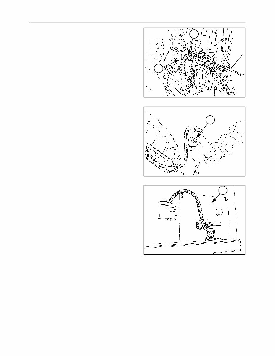
SECTION 1 - GENERAL INFORMATION 1-2 Wire Harness Connector Bracket The wire harness connector bracket, 1, is mounted on the rear of the tractor to connect the baler wiring harness, 2, to the tractor harness. The tractor harness is divided to connect to the operators panel and also to the power source. 20021693 2 1 2 Remote Override Switch In the event that the Bale Command Plus operators panel or controller become inoperable, a Remote Override switch, 1, is provided to allow wrapping and ejection of the current bale. The switch is installed on the wiring harness near the operators panel and will control the operation of the net or twine actuators when the remote override lead is connected to the respective actuator on the baler. 20022010 1 3 BALER-MOUNTED COMPONENTS Controller The controller, 1, processes the information from the various sensors and the operators panel to control the operation of the Bale Command Plus system based on the information it receives. It must be set for the model of the baler it is installed on for it to function properly. It processes signals from the actuator position, bale size, bale shape, tailgate position and net counter roll sensors. It sends signals to the operators panel to display information for the operator. It also contains solid-state relays that supply power to the wrap actuators and net/twine actuator selector relay. The Bale Slice actuator extend and retract relays are also in the controller if equipped with the Bale Slice option. Remote Override Lead An electrical lead is used to connect the switch to one of the actuators. This lead is normally disconnected and stored in the vicinity of the controller box. If bale slice had been engaged when failure of the controller or operators panel occurred, the slicing knives will have to be manually disengaged to continue bale operation. NOTE: The net or twine will be cut if bale slice is engaged while wrapping. 20021992 1 4 NOT FOR REPRODUCTION
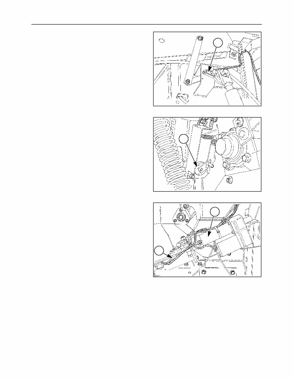
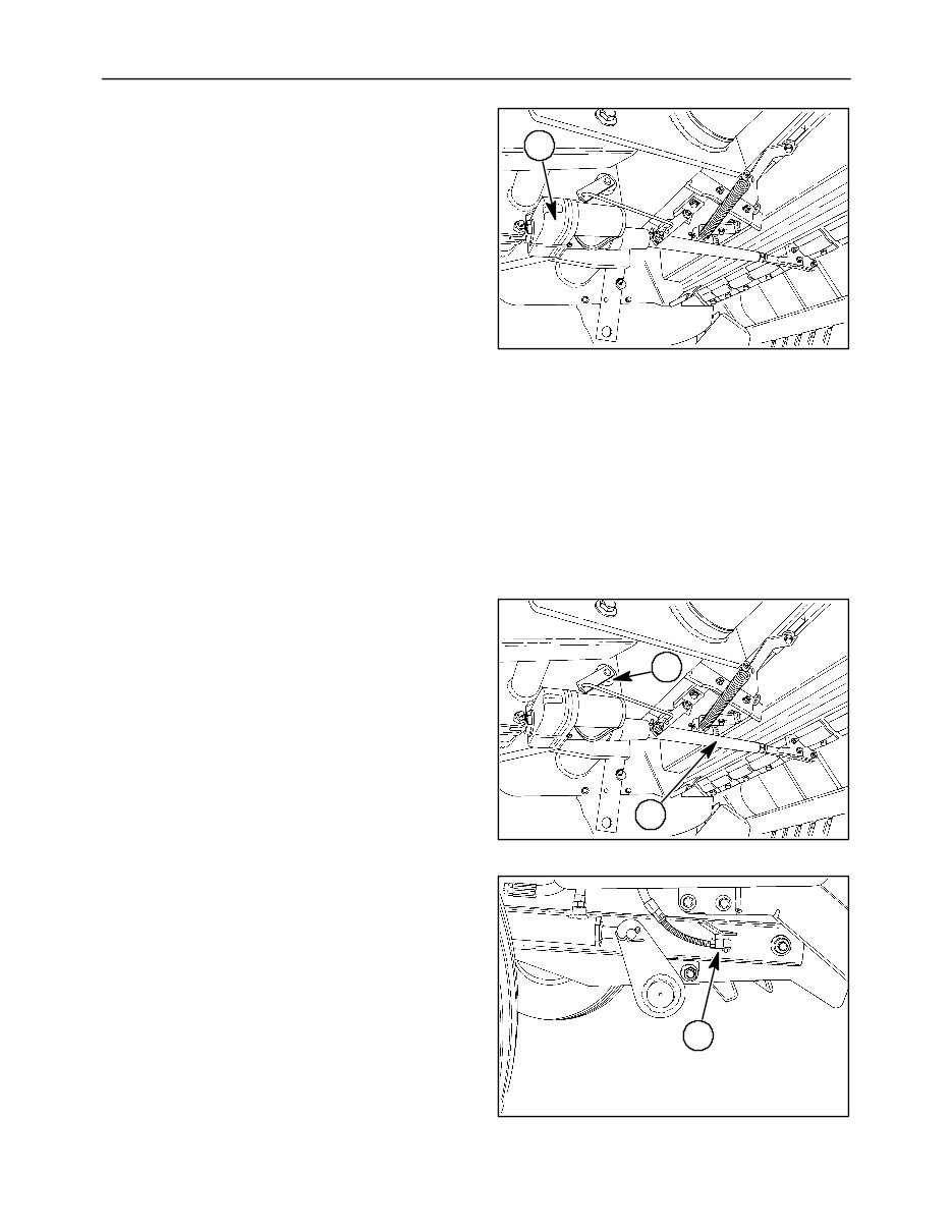
SECTION 1 - GENERAL INFORMATION 1-3 Bale Size Sensor The bale size sensor, 1, is a rotary potentiometer that changes the level of its return signal to the controller based on the amount of rotation of the sensor rotor section that is connected through linkage to the bale-forming belt take-up arm. The controller converts the signal to a bale size and displays the size on the operators panel. 20021998 1 5 Bale Shape Sensors (right side only shown) The bale shape sensors, 1, are rotary potentiometers that change the level of the return signal to the controller based on the amount of rotation of the sensor center section that is connected through linkage to the bale shape spring inside the bale chamber. The controller converts the signal to display the appropriate sections of the bar graphs on the operators panel. 20021997 1 6 Twine Wrapper Actuator The twine wrapper actuator, 1, moves the pivot link to operate the twine tubes and also opens and closes the twine knives. Twine Wrapper Sensor The sensor, 2, mounted on the actuator monitors the position of the actuator. The twine wrapper sensor is a rotary potentiometer that changes the level of the return signal to the controller based on the amount of rotation of the center section. The sensor transmits the exact position of the twine tubes to provide various wrapping configurations to the operator. One programmable custom wrap configuration is pro- vided. 20021995 1 2 7 NOT FOR REPRODUCTION
SECTION 1 - GENERAL INFORMATION 1-4 Net Wrapper Actuator The net wrapper actuator, 1, moves the linkage to operate the net wrap duckbill and knife. Net Wrapper Actuator Position Sensor The net wrapper actuator sensor, 2, is a rotary potentiometer that changes the level of its return signal to the controller based on the amount of rotation of the sensor rotor. The controller converts the signal to determine the position of the duckbill. 20021993 2 1 8 Net Counter Roll Sensor and Magnet As the net counter roll magnet, 1, rotates past the sensor, 2, the return signal to the controller changes. The sensor is a magnetically activated solid-state switch. When a magnet is close to the sensor, the circuit is closed. When the magnet is away from the sensor, the circuit is open. The controller senses the open or closed circuit to count the revolutions of the counter roll. The controller monitors the signal changes to determine that the net has started to wrap on the bale and move the duckbill to the precut position. The controller continues to count the number of signal changes to determine the amount of net to be wrapped on the bale. 20021996 2 1 9 Tailgate Sensor The tailgate sensor, 1, monitors the position of the tailgate. The sensor is a ferrous proximity switch. When the tailgate latchpin is close to the sensor, the circuit is closed. When the tailgate latchpin is away from the sensor, the circuit is open. The controller senses the open or closed circuit to determine whether the tailgate is open or closed. If the sensor moves away from the tailgate latchpin for 15 seconds, the controller will activate the alarm on the operators panel and display an error message. If the sensor moves away from the tailgate during the wrap cycle, the controller will activate the alarm on the operators panel, display an error message, and the wrap cycle will be stopped. When the tailgate closes, the controller uses the signal to reset the display for the next bale and add 1 to the bale count if the bale was wrapped in the automatic mode. 20021994 1 10 NOT FOR REPRODUCTION
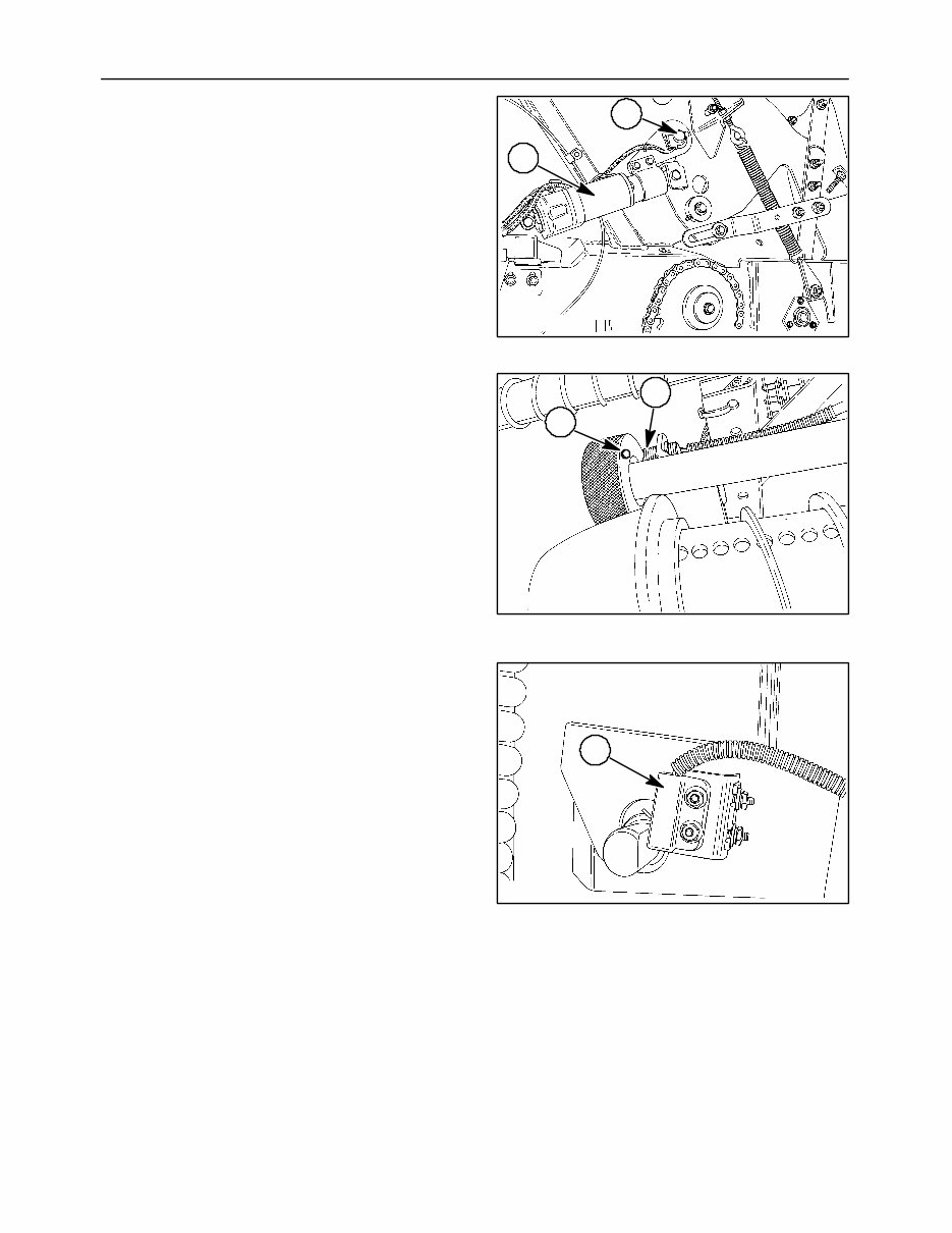
SECTION 1 - GENERAL INFORMATION 1-5 Bale Slice Actuator When the Bale Slice system is turned ON, the controller will extend the actuator, 1, to move the knives into position to slice the bale when the bale size sensor indicates that the core is formed. Just before the bale reaches the preset full bale size, the controller will retract the actuator and move the knives to the home position. The controller can be set to retract the actuator to leave 2″,4″, or 6″ of uncut material when the twine wrapper is selected, or to leave 0″,2″,4″, or 6″ of uncut material when the net wrapper is selected. The initial factory setting is 2″. To change the setting, refer to Setup/Diagnostic item 4. For example, if the controller is set to leave 2″ of uncut material, when the bale reaches 4″ less than the preset full bale size, the controller will retract the actuator and move the knives to the home position to allow the twine or net to be placed on approximately 2″ of uncut material. NOTE: The amount of uncut material will vary from the set amount depending on the windrow size. 20021999 1 11 Bale Slice Actuator Position Sensor The Bale Slice actuator sensor, 1, is a rotary potentiometer that changes the level of its return signal to the controller based on the amount of rotation of the sensor rotor (center section) that is connected through linkage to the knife operating arm, 2. The controller converts the signal to determine the position of the actuator. 20021999 1 2 12 Rotor Cutter Knife Sensor The rotor cutter knife position sensor, 1, monitors the position of the knives. The sensor is a ferrous proximity switch. When the knives are fully engaged in the cut position, the circuit is closed. When the knives are not fully engaged, the circuit is open. The controller senses the open or closed circuit to determine the knife position. Knife full engagement is indicated on the display by the SLICE triangle being on. The slice indicator is turned off when the knives are not fully engaged. 20022009 1 13 NOT FOR REPRODUCTION
SECTION 1 - GENERAL INFORMATION 1-6 HOW THE BALE COMMAND PLUS SYSTEM OPERATES NOTE: The Bale Command system is designed for use with a 12-volt negative ground system only. The following describes the automatic operation of the Bale Command Plus system during the formation and wrapping of a 60″ bale with the Bale Slice system turned ON. Balers without the Bale Slice option operate the same except for the references to the Bale Slice system. BALE FORMATION - TWINE OR NET As the bale size increases (after the core is formed), the linkage from the take-up arm, 1, moves the bale size sensor arm, 2, and changes the output signal to the controller. 20021998 1 2 14 The controller converts the signal to bale size and changes the display on the operators panel. The left and right bale shape sensors also send signals to the controller which uses the signals to change the height of the respective bar graph. This provides a guide for the operator to produce a uniform bale. 50020406 15 NOT FOR REPRODUCTION
SECTION 1 - GENERAL INFORMATION 1-7 The Bale Command Plus offers a near full bale alarm/indicator to alert the operator that the bale is almost complete. When the bale being made reaches the near full bale set point, the alarm will sound for 0.5 seconds and the full bale bracket symbol will flash until the bale reaches full size. NOTE: The value of 32″ is the minimum bale size the near full bale alarm/indicator can be activated. For example: if the near full bale alarm/indicator size is set at 6″, and the full bale size is 36″, the near full bale alarm/indicator will sound and the full bale bracket symbol will be flashing when the bale reaches 32″. The near full bale alarm/indicator can be set at 2, 4 or 6″ before full bale size. Setting the value to zero will turn off the feature. Refer to Setup/diagnostic item 7 for instruction to change the setting. 50020406 16 When the bale reaches full size, the full bale size will be displayed in solid brackets, the Full Bale indicator light will turn on, and the alarm will sound for three seconds. After a short delay, the controller will start the wrapping cycle. The operator should stop forward motion as soon as the full bale alarm is activated. 50020406 17 After the wrapping cycle is completed, the controller will send a signal to the operators panel to tell the operator to eject the bale. When the tailgate is closed after the bale is ejected, the tailgate sensor will be activated to reset the controller for the next bale and add 1 to the bale count. The operators panel will beep to indicate the tailgate is latched so the operator can start forming the next bale. 50020406 18 NOT FOR REPRODUCTION
This operator's manual is an essential guide for operators of the New Holland BR740A, BR750A, BR770A, BR780A round balers. It provides detailed instructions on the operation, adjustment, and maintenance of the Bale Command Plus system, tailored to the specific models mentioned above. The manual is designed to enhance the functionality and productivity of baling operations.
Operators will find step-by-step guidance on setting up the system, making adjustments for different crops and conditions, and troubleshooting common issues. Additionally, essential maintenance procedures are covered to ensure reliable and efficient operation of the baler, emphasizing the importance of regular checks and maintenance routines to prevent downtime and extend the service life of the equipment.
The manual aims to help operators optimize the performance of their New Holland balers, achieve consistent and high-quality bales, and promote safe operation practices. Available in digital format, this operator's manual ensures that vital information is readily accessible, providing operators with a valuable reference tool that can be consulted anytime, anywhere, to support their daily operations and maintenance tasks.
Printable: Yes Language: English Compatibility: Pretty much any electronic device, incl. PC & Mac computers, Android and Apple smartphones & tablets, etc. Requirements: Adobe Reader (free)