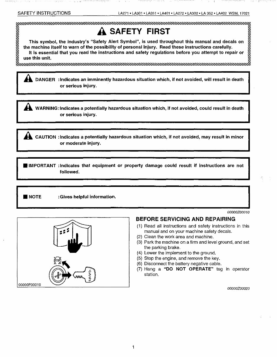
SAFETY INSTRUCTIONS LA271 • LA301 • LA351 • LA401 • LA272 • LA302· LA 352· LM02 WSM, 17021 A SAFETY FIRST This symbol, the industry's "Safety Alert Symbol", is used throughout this manual and decals on the machine itself to warn of the possibility of personal injury. Read these instructions carefully. It is essential that you read the instructions and safety regulations before you attempt to repair or use this unit. A DANGER :Indicates an imminently hazardous situation which, if not avoided, will result in death or serious injury. A WARNING:lndicates a potentially hazardous situation which, if not avoided, could result in death or serious injury. A CAUTION :Indicates a potentially hazardous situation which, if not avoided, may result in minor or moderate injury. • IMPORTANT :Indicates that equipment or property damage could result if instructions are not followed. I • NOTE :Gives helpful information. I ....._--------- OOOOOZ00010 BEFORE SERVICING AND REPAIRING (1) Read all instructions and safety instructions in this manual and on your machine safety decals. (2) Clean the work area and machine. (3) Park the machine on a firm and level ground, and set the parking brake. (4) Lower the implement to the ground. (5) Stop the engine, and remove the key. (6) Disconnect the battery negative cable. (7) Hang a "DO NOT OPERATE" tag in operator station. 00000F00010 OOOOOZ00020 1
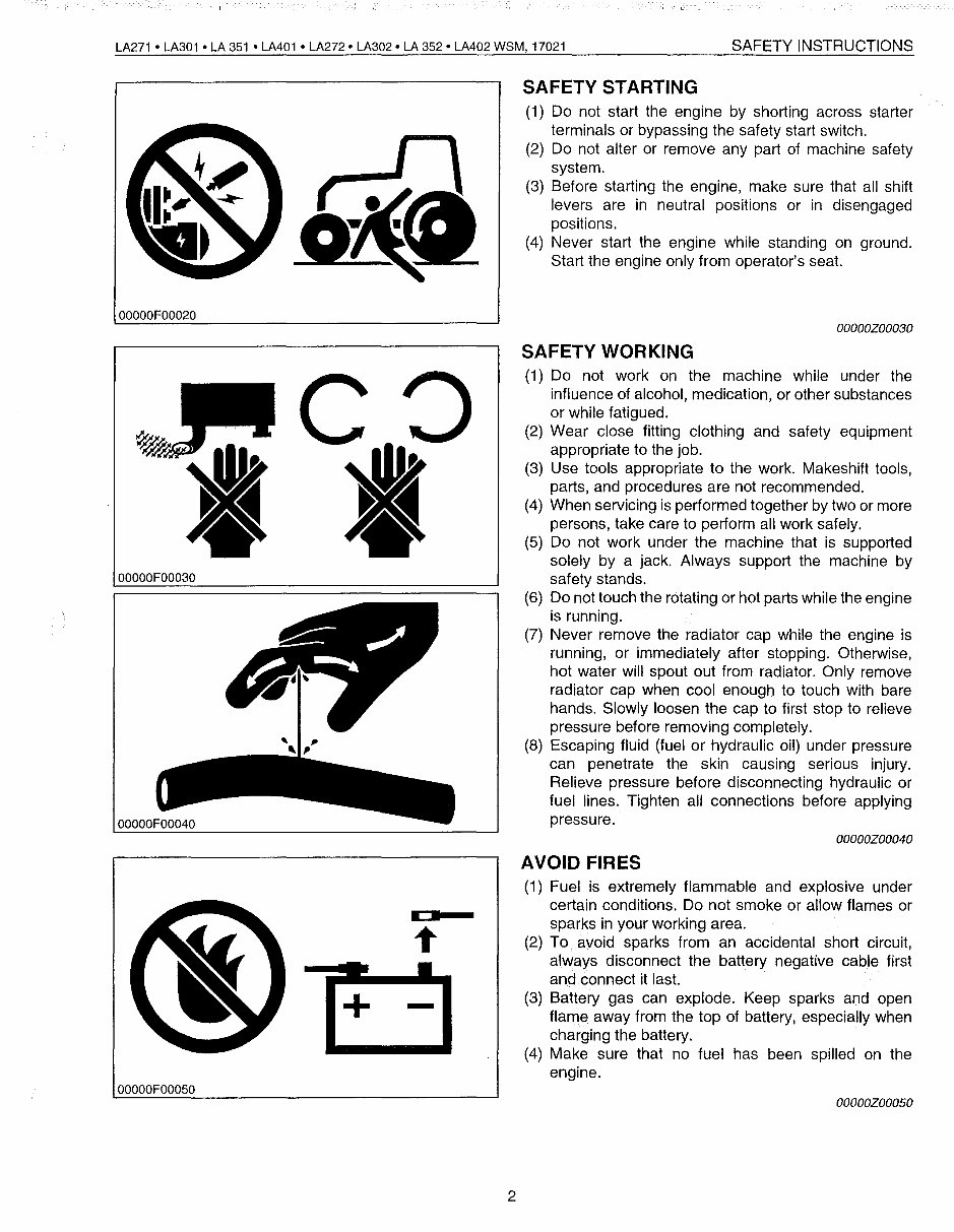
LA271 • LA301 • LA 351 • LA401 • LA272· LA302· LA 352· LA402 WSM, 17021 SAFETY INSTRUCTIONS SAFETY STARTING (1) Do not start the engine by shorting across starter terminals or bypassing the safety start switch. (2) Do not alter or remove any part of machine safety system. (3) Before starting the engine, make sure that all shift levers are in neutral positions or in disengaged positions. (4) Never start the engine while standing on ground. Start the engine only from operator's seat. 00000F00020 OOOOOZ00030 00000F00030 , SAFETY WORKING (1) Do not work on the machine while under the influence of alcohol, medication, or other substances or while fatigued. (2) Wear close fitting clothing and safety equipment appropriate to the job. (3) Use tools appropriate to the work. Makeshift tools, parts, and procedures are not recommended. (4) When servicing is performed together by two or more persons, take care to perform all work safely. (5) Do not work under the machine that is supported solely by a jack. Always support the machine by safety stands. (6) Do not touch the rotating or hot parts while the engine is running. (7) Never remove the radiator cap while the engine is running, or immediately after stopping. Otherwise, hot water will spout out from radiator. Only remove radiator cap when cool enough to touch with bare hands. Slowly loosen the cap to first stop to relieve pressure before removing completely. (8) Escaping fluid (fuel or hydraulic oil) under pressure can penetrate the skin causing serious injury. Relieve pressure before disconnecting hydraulic or fuel lines. Tighten all connections before applying pressure. OOOOOZ00040 00000F00050 + • - 2 AVOID FIRES (1) Fuel is extremely flammable and explosive under certain conditions. Do not smoke or allow flames or sparks in your working area. (2) To avoid sparks from an accidental short circuit, always disconnect the battery negative cable first and connect it last. (3) Battery gas can explode. Keep sparks and open flame away from the top of battery, especially when charging the battery. (4) Make sure that no fuel has been spilled on the engine. OOOOOZ00050
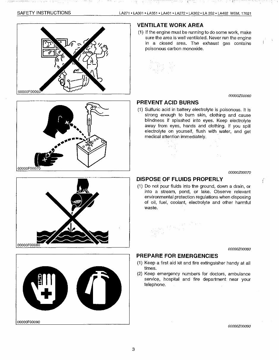
SAFETY INSTRUCTIONS 00000F00060 LA271 • LA301 • LA351 • LA401 • LA272· LA302· LA 352· LA402 WSM, 17021 VENTILATE WORK AREA (1) If the engine must be runn ing to do some work, make sure the area is well ventilated. Never run the engine in a closed area. The exhaust gas contains poisonous carbon monoxide. OOOOOZ00060 PREVENT ACID BURNS (1) Sulfuric acid in battery electrolyte is poisonous. It is strong enough to burn skin, clothing and cause blindness if splashed into eyes. Keep electrolyte away from eyes, hands and clothing. If you spill electrolyte on yourself, flush with water, and get medical attention immediately. OOOOOZ00070 DISPOSE OF FLUIDS PROPERLY (1) Do not pour fluids into the ground, down a drain, or into a stream, pond, or lake. Observe relevant environmental protection regulations when disposing of oil, fuel, coolant, electrolyte and other harmful waste. OOOOOZOOOBO ( 00000F00090 PREPARE FOR EMERGENCIES (1) Keep a first aid kit and fire extinguisher handy at all times. (2) Keep emergency numbers for doctors, ambulance service, hospital and fire department near your telephone. OOOOOZ00090 3
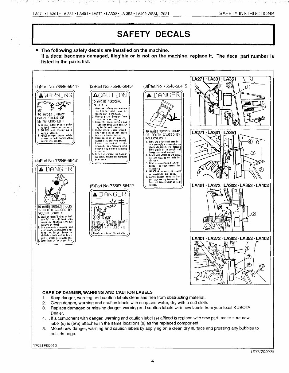
LA271 • LA301 • LA 351 • LA401 • LA272· LA302· LA 352· LA402 WSM, 17021 SAFETY INSTRUCTIONS I S_A_F_E_T_Y_D_E_C_A_LS I • The following safety decals are installed on the machine. If a decal becomes damaged, illegible or is not on the machine, replace it. The decal part number is listed in the parts list. LA401 . LA272 . LA302 . LA352 . LA402 v' LA401 . LA272 . LA302 . LA352 . LA402 o TO AVOIO SERIOUS INJURY OR DEATH CAUSED BY ROLLOVERS : I. RCfS and a fastened stat btlt are SHongl') recOMeroded tn alll:lst ill appliutions. foldable R<fS should b' in upr ighl .nd lockedpoSlliOtlllflJJipPtd. 2. Adjust rear whtels to the widest setting tN.1 is sUllable for Ill< uDlI. 1. Add r eCOo'M\ended whee I ballast or rtar uught for 4. 00 l()J dr ive on sleep slepes or unstabl e sud aces. S. Carry loader aflls at low position lransPQt'l. Hovt' and urn tractor al slOll speeds. (3)Part No. 75546-56415 A DANGER TO AVOID PERSONAL INJURY : I. Obstfve sa( et IJ pr ecaul ions In loader and tractor Operator's Manual. 2. Operate the loader (rQlll tractor seat onl!;l. 3. Keep children. others and Iivestock when operat- Ing loader and traclGt. 4. Il'o'oid holes. loose ground. and rodes which Illy cause trlCH" I lOader \0 t lP· S. \lhen parking or storing. choosc f1.1 and hard 9'oood. lower the bucket to the ground. set brakes and rel'lO'o'e key before leaving tractor. 6. Be(cw(' disconnecting hyO-au· lie IiNS. ,elieveilll hoJ*aulic pressur ('. (2)Part No. 75546-56451 ACAUTION (5)part No. 75567-56422 TO AVOID SERIlXJS lNJlJlY OR DEATH CAUSED BY FALLl NG LOADS : I. Load on ra I sed bucker or r ..1 can fall Of roll back onlo operator causing set ious in;urlJ or dealh. 2. Use approved c1allping and lor guard atlachotents ror handl i"9 Iat gr. IDose or shHtabl, loads such as bal", pOSIS, sht<ls 01 pl\,<ood ,Ic. 1. h.ds as I.. as pOsslbl" AWARNING TO AVOID INJURY FROM FALLS OR BEING CRUSHED : I. 00 my or work under raised loader or bucket. 2. DO NOT use loader as a work platter •. 1. HEVER connect chain. cable .. roP' to load« bucl,t whJl& operating loader. (1)Part No. 75546-56441 (4)Part No. 75546-56431 A DANGER (f" CARE OF DANGER, WARNING AND CAUTION LABELS 1. Keep danger, warning and caution labels clean and free from obstructing material. 2. Clean danger, warning and caution labels with soap and water, dry with a soft cloth. 3. Replace damaged or missing danger, warning and caution labels with new labels from your local KUBOTA Dealer. 4. .If a component with danger, warning and caution label (s) affixed is replace with new part, make sure new label (s) is (are) attached in the same locations (s) as the replaced component. 5. Mount new danger, warning and caution labels by applying on a clean dry suriace and pressing any bubbles to outside edge. 17021F00010 17021Z00020 4
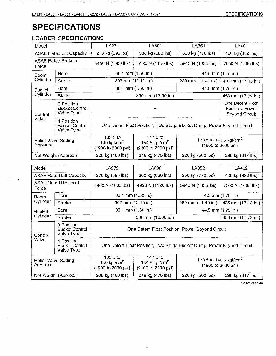
LA271 • LA301 • LA351 • LA401 • LA272' LA302' LA352' LA402 W8M, 17021 SPECIFICATIONS LOADER SPECIFICATIONS SPECIFICATIONS Model LA271 LA301 LA351 LA401 ASAE Rated Lift Capacity 270 kg (595 Ibs) 300 kg (660 Ibs) 350 kg (770 Ibs) 400 kg (882 Ibs) ASAE Rated Brakeout 4450 N (1000 Ibs) 5120 N (1150 Ibs) 5940 N (1335 Ibs) 7060 N (1586 Ibs) Force Boom Bore 38.1 mm (1.50 in.) 44.5 mm (1.75 in.) Cylinder Stroke 307 mm (12.10 in.) 289 mm (11.40 in.) 435 mm (17.13 in.) Bucket Bore 38.1 mm (1.50 in.) 44.5 mm (1.75 in.) Cylinder Stroke 330 mm (13.00 in.) 450 mm (17.72 in.) 3 Position One Detent Float Bucket Control - Position, Power Control Valve Type Beyond Circuit Valve 4 Position Bucket Control One Detent Float Position, Two Stage Bucket Dump, Power Beyond Circuit Valve Type Relief Valve Setting 133.5 to 147.5 to 133.5 to 140.5 kgf/cm 2 140 kgflcm 2 154.6 kgflcm 2 Pressure (1900 to 2000 psi) (2100 to 2200 psi) (1900 to 2000 psi) Net Weight (Approx.) 208 kg (460 Ibs) 216 kg (475 Ibs) 226 kg (500 Ibs) 280 kg (617 Ibs) Model LA272 LA302 LA352 LA402 ASAE Rated Lift Capacity 270 kg (595 Ibs) 300 kg (660 Ibs) 350 kg (770 Ibs) 400 kg (882 Ibs) ASAE Rated Brakeout 4460 N (1005Ibs) 4990 N (1120 Ibs) 5940 N (1335 Ibs) 7500 N (1685 Ibs) Force Boom Bore 38.1 mm (1.50 in.) 44.5 mm (1.75 in.) Cylinder Stroke 307 mm (12.10 in.) 289 mm (11.40 in.) 435 mm (17.13 in.) Bucket Bore 38.1 mm (1.50 in.) 44.5 mm (1.75 in.) Cylinder Stroke 330 mm (13.00 in.) 450 mm (17.72 in.) 3 Position Bucket Control One Detent Float Position, Power Beyond Circuit Control Valve Type Valve 4 Position Bucket Control One Detent Float Position, Two Stage Bucket Dump, Power Beyond Circuit Valve Type Relief Valve Setting 133.5 to 147.5 to 133.5 to 140.5 kgf/cm 2 140 kgf/cm 2 154.6 kgf/cm 2 Pressure (1900 to 2000 psi) (2100 to 2200 psi) (1900 to 2000 psi) Net Weight (Approx.) 208 kg (460 Ibs) 216 kg (475 Ibs) 226 kg (500 Ibs) 280 kg (617 Ibs) 17021Z00040 6
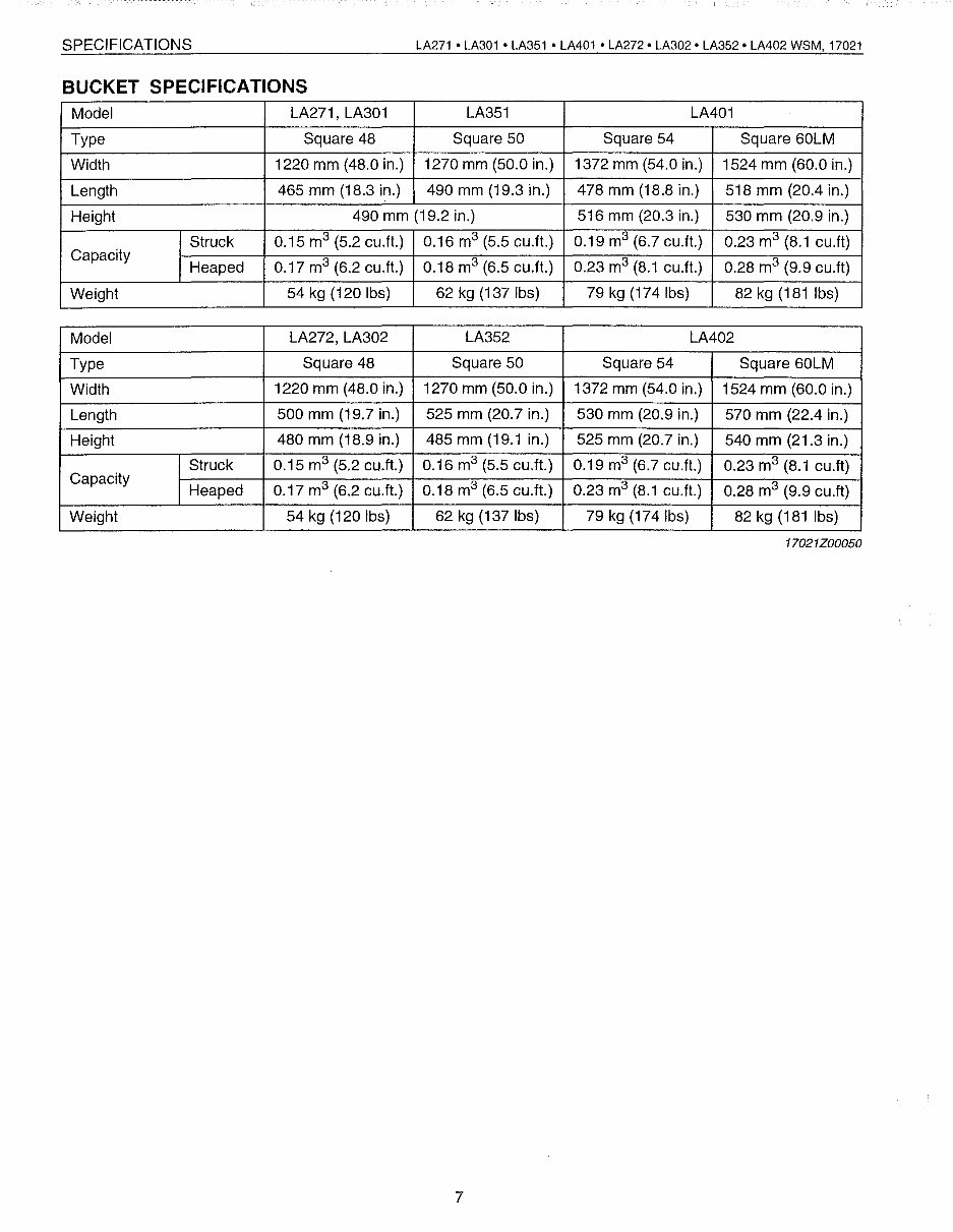
SPECIFICATIONS BUCKET SPECIFICATIONS LA271 • LA301 • LA351 • LA401 • LA272· LA302· LA352· LA402 WSM, 17021 Model LA271, LA301 LA351 LA401 Type Square 48 Square 50 Square 54 Square 60LM Width 1220 mm (48.0 in.) 1270 mm (50.0 in.) 1372 mm (54.0 in.) 1524 mm (60.0 in.) Length 465 mm (18.3 in.) 490 mm (19.3 in.) 478 mm (18.8 in.) 518 mm (20.4 in.) Height 490 mm (19.2 in.) 516 mm (20.3 in.) 530 mm (20.9 in.) Struck 0.15 m 3 (5.2 cu.ft.) 0.16 m 3 (5.5 cu.ft.) 0.19 m 3 (6.7 cu.ft.) 0.23 m 3 (8.1 cu.ft) Capacity Heaped 0.17 m 3 (6.2 cu.ft.) 0.18 m 3 (6.5 cu.ft.) 0.23 m 3 (8.1 cu.ft.) 0.28 m 3 (9.9 cu.ft) Weight 54 kg (120 Ibs) 62 kg (137 Ibs) 79 kg (174 Ibs) 82 kg (181 Ibs) Model LA272,LA302 LA352 LA402 Type Square 48 Square 50 Square 54 Square 60LM Width 1220 mm (48.0 in.) 1270 mm (50.0 in.) 1372 mm (54.0 in.) 1524 mm (60.0 in.) Length 500 mm (19.7 in.) 525 mm (20.7 in.) 530 mm (20.9 in.) 570 mm (22.4 in.) Height 480 mm (18.9 in.) 485 mm (19.1 in.) 525 mm (20.7 in.) 540 mm (21.3 in.) Struck 0.15 m 3 (5.2 cu.ft.) 0.16 m 3 (5.5 cu.ft.) 0.19 m 3 (6.7 cu.ft.) 0.23 m 3 (8.1 cu.ft) Capacity Heaped 0.17 m 3 (6.2 cu.ft.) 0.18 m 3 (6.5 cu.ft.) 0.23 m 3 (8.1 cu.ft.) 0.28 m 3 (9.9 cu.ft) Weight 54 kg (120 Ibs) 62 kg (137 Ibs) 79 kg (174Ibs) 82 kg (181 Ibs) 17021Z00050 7
Upon purchasing this manual, you will receive a .PDF file containing an email address for further assistance. After contacting the provided email, you will receive a reply with a link to access the manual for your Kubota LA302 Loader.
This comprehensive manual covers every aspect of your machine, providing detailed instructions for tasks ranging from an oil change to a transmission swap. With hundreds of pages, it includes numerous illustrations to assist you and easy-to-understand text. The manual also features a search function, allowing you to navigate and print specific pages as needed.
The Factory Service Repair Manual offers a step-by-step guide to maintaining and repairing your Kubota LA302 Loader, equipping you with the knowledge typically possessed by factory-trained technicians. By utilizing the information within this manual, owners can confidently make informed decisions regarding the maintenance and repair of their machine.
For those seeking high-quality service manuals, we not only guarantee exceptional manual content but also provide dedicated customer service to ensure your satisfaction. For additional service manuals, please visit www.johnsmanuals.com.
Recently Viewed
5,521,897Happy Clients
2,594,462eManuals
1,120,453Trusted Sellers
15Years in Business
Price:
Actual Price:
Kubota LA302 Loader Factory Service & Work Shop Manual